Rochester Institute of Technology
RIT Scholar Works
Theses
Thesis/Dissertation Collections
2001
Evaluation of the structural design of new liquid
containers
Jadranka Mandic
Follow this and additional works at:
http://scholarworks.rit.edu/theses
This Thesis is brought to you for free and open access by the Thesis/Dissertation Collections at RIT Scholar Works. It has been accepted for inclusion in Theses by an authorized administrator of RIT Scholar Works. For more information, please [email protected].
Recommended Citation
EVALUATION
OF
THE STRUCTURAL
DESIGN
OF NEW LIQUID CONTAINERS
by
Jadranka Mandic
A Thesis
Submitted
to
the Department
ofPackaging
Science
ofRochester Institute
ofTechnology
Executive
Leader Program
2001
Department of Packaging Science
of Rochester Institute of Technology
Rochester, New York
CERTIFICATE OF APPROVAL
M.S. Degree
The M.S. degree thesis of Jadranka Mandie
has been examined and approved
by the thesis committee as satisfactory
for the thesis requirements for the
Master of Science degree
Dan Goodwin
CarI de Winter
Acknowledgements
[would like to thankallwhohelpedme withtheprofessionaladvice, as well as those who gave me support and understanding
during
preparation and realizationofthisproject.Iam thankful toMr. Miso Rabatic for confidence hegave me, to work out
his
patent. I am very grateful to prof. dr. MladenSercer,
PolymerDepartment,
forhis
motivation in the development ofthis project, Iowe alarge
part of my gratitude to prof. dr. BojanJerbic,
Igor Cerin and personnel of CAD Lab allfromFaculty
of MechanicalEngineering
and Naval ArchitectureoftheUniversity
ofZagreb.Prof.
dr.
VjeraKrstelj
deserves the most ofmy appreciation andgratitude for herencouragementand support.- Thank
EVALUATION
OF
THE
STRUCTURAL
DESIGN
OF NEW LIQUID
CONTAINERS
by
Jadranka Man
die
March 2001
ABSTRACT
GECOS (Global
EcoSystem)
bottle
with an additional using quality, representsnew
idea,
whichis
patentedinnovation.
Basicbottleassignment ofGECOS bottleis for storage andtransportation ofthe liquids
from
fooddomain,
such as water,juices or milk. Additional using quality of GECOS bottles comes from unique
construction,as well astheir closures. When GECOS bottle is empty it can serve
as universal
building
elements, which are connectedby
closures as connecting elements into new three-dimensional structures. In such a way, the bottles areeasier to be
kept,
collected or used in a game asdidactic
and creative tool likebuilding
blocks.In this thesis basic idea on GECOS
bottle design is
worked outfrom
structuraldesign point of view, using analytical approach. Supported
by
CAD (ComputerAided
Design)
system, 3D model of GECOS bottle was created and translated into FEA (Finite ElementAnalysis)
model. With quantified factors which arenecessary for structural design analysis the calculation ofstress and
deformation
TABLE
OF
CONTENTS
1.
INTRODUCTION
1
2. INVENTION
ESSENCE
2
3.
PRODUCT
DEVELOPMENT
PROCESS
43.1. CONCEPT
DEVELOPING
7
3.1.1.
FUNCTIONAL REQUIREMENTS
8
3.1.2.
MATERIAL
SELECTION
10
3.1.3. PROCESS OF PRODUCTION
12
3.1.4. CONCEPTUAL DESIGN
13
3.2. STRUCTURAL DESIGN
19
3.2.1. DESIGN METHODOLOGY
20
3.2.2. QUANTIFYING THE DESIGN PROBLEM
22
3.2.2.1. Part geometry
23
3.2.2.2.
Generating
the mesh24
3.2.2.3. Material
mechanical properties25
3.2.2.4.
Boundary
conditions26
3.2.2.5.
Loading
conditions 273.2.3. RESULTS
30
LIST OF FIGURES
Fig. 1. DrawingsofGECOS bottle from thepatentapplication 3
Fig. 2. Flowchartofproductdevelopmentprocess 4
Fig. 3. Flowchart oftechnological developmentoftheproduct 5
Fig. 4. Flowchartofthesismethodology 6
Fig. 5. Technologicalrequirements 7
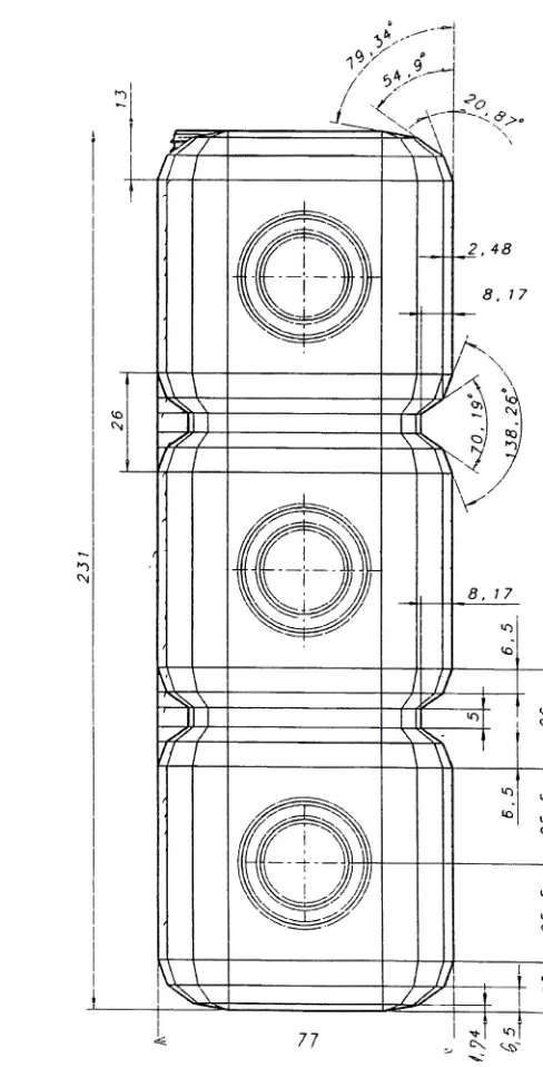
Fig. 6. Frontview ofthree partsquareGECOS bottle 15
Fig. 7. Frontview ofthreepartsquareGECOS bottle 15
Fig. 8. Crosssection andbottomview of squareGECOS bottle 16
Fig. 9.
Top
view ofsquareGECOS bottle 16Fig. 10. Closure 16
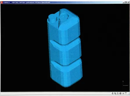
Fig. 11. 3D GECOS bottlemodel (printscreenfrom l-DEAS software) 17
Fig. 12. 3D GECOS bottlemodel with closure (printscreenfrom l-DEAS software) 17
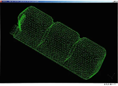
Fig. 13. Wireframeof3DGECOS bottlemodel(printscreenfrom l-DEAS software) 18
Fig. 14. Simplified 3D GECOS bottlemodel preparedfor meshing 23
Fig. 15. Finalelement model ofGECOS bottle (printscreenfrom l-DEAS software) 24
Fig. 16. Idealizedconditions of supportedbottomofGECOS bottle 26
Fig. 17. Report from CAPE99 (bestsolution underNo.
1.)
28Fig. 18. Idealized
loading
conditions 29Fig. 19. Resultsofstresson MODEL A 30
Fig.20. Resultsof stress on
top
ofMODEL A 31Fig. 21. Resultsof stress onbottomofMODEL A 31
Fig. 22. Resultsof stress onMODEL B 32
Fig. 23. Resultsof stress on
top
ofMODEL B 33Fig. 24. Resultsofstress on bottomofMODEL B 33
Fig. 25. ResultsofdisplacementonMODELA 34
Fig. 26. Resultsofdisplacementon
top
ofMODEL A 35Fig.27. ResultsofdisplacementonbottomofMODEL A 35
Fig. 28. Results ofdisplacementonMODEL B 36
Fig. 29. Results ofdisplacementon
top
ofMODEL B 37Fig. 30. ResultsofdisplacementonbottomofMODEL B 37
LIST
OF
TABLESTable 1.Averagevalues of material mechanicalproperties 25
Table 2. Solutionreport 28
1. INTRODUCTION
Confronted with the
fact,
that the containersfor
liquids aredaily
produced andthrown away
in
enormous quantities, and that some ofthem have no using quality afterbeing
emptied while the construction of the same one aggravates the disposal andrecycling, the idea has appeared
by
which to the containers, aftertheir basic use, anotherusing quality isadded.
The
former
liquid packaging ways, particularly in the foodindustry,
for examplestandard so-called PET containers,
tetrapack,
glassbottles,
tins and other similarcontainers,
have
the samemaindrawback
-after
being
emptied,they
were mostfrequently
beenthrownaway intorefuse. The ecological standards ofthedevelopedcountries "force"
the users of used containers to dispose the same one additionally into special disposal
places assigned for that purpose, in order to be recycled. Used containers are disposed
individually
or in smaller quantities, and,inherently,
they
are of no interest to theconsumer,butadditional worry.
By
this invention - GECOS (Global EcoSystem)
bottle just these drawbacks areeliminated. GECOS bottle is container for
liquids,
which on its surface, have additionalparts, which enable the connecting oftwo or more GECOS bottlestogether in away,that three-dimensional structures can be created. These structures enable easier
transport,
storage, as well as the playing and amusement for children. Such greater quantity, once
gathered
together,
"justifies"the transporttoeven more distanced disposalplaces,because
additional plastic containers
-sacks and the
like,
fortaking
away the empty GECOSbottles,
are not necessary.Simply,
the entire block of empty GECOSbottles
is verymonolithic, lightand simplefortransportation.
With different geometry and volumes of this bottles it is possible to make
combinations ofthree-dimensional structures. It can be used in children's play as
didactic
and creative
toy
asbuilding
blocks.This invention is product of Mr. Miso Rabatic. The State Intellectual
Property
Office receivedthe patent application with number
P20000021A,
andPatentCooperation
Treaty
(PCT/HR00/00001). Since there is a greatinterest for
suchinvention,
the goal of2.
INVENTION ESSENCE
The proposed technical solution offers an additional using quality ofused bottles.
The
invention
noveltyis,
that it combines existing advantages ofthe plastic bottles with special construction ofthebottle
andbelonging
closure.The GECOS
bottles
are threedimensional
building
elements of special surfacetopology. The invention in its essence consistsofthebottle construction, which in its sides
has
sunk connecting places, shaped to accept the closure as the connecting element. Inorder to ensure a compact coupling
by
the closure, the closure outer diameter is greaterthan the diameter ofthe connecting place in the bottle sunkage, it is toothed with small
elastic teethwhich enablethenecessary deformation. The closure is constructed inaway,
that in the middle it has a horizontal partition wall and only on one side a thread. The
closureensureinter connectingoftwo GECOS bottles
by
pressing into connectingplace ofonebottlewith pressing-in into connectingplace ofotherbottle. Measure"a"
defines dimension
oftheside ofGECOS bottlebasic
shape-the cube,
as well as distance betweenthe centers ofthe connecting places onthe
bottle,
in order toensure the compatibility in their
inter-connecting,
regardless ofthe size and shape of all bottleswhich come as resultfromthisinvention.The drawings in patent application is offering one, two and three part square
GECOS bottle. Threepart square GECOS bottle has been takeninto consideration. Bottle
VIEWD 1
CROSS SECTION K-K
L CROSSSECTION L-L
i
,VIEWE CROSS SECTION M-M
}f\
\
V
J
[image:10.520.83.473.68.356.2]3.
PRODUCT
DEVELOPMENT
PROCESS
The
idea
orinnovation
have
to pass the product development process to becomecommercialproduct.
i
1
^.
Marketing
Analyze ^ Requirements for ^ *" Development Evaluation of Product Development A ?I
Idea (problem assignment) >Planning
i_
_^. Technological ^_
Design
I
Design optimizationTechnological
Evaluation
[image:11.520.27.493.116.457.2]Drawing
oftechnicaland manufacture documentsFig. 2. Flowchart of productdevelopmentprocess[1
]
Developmentofnew product
begins
withresearch anddevelopment
planning. Thisphase establishes need for product manufacture according to the buyers' requests,
marketing analyses, trend studying, analyses results of production
techniques,
or someother criteria. In this case, request
for development
comesfrom idea
of anindividual
aspatentedinnovation. Request for product
development
describes
development
goals andit
can
be
understoodas engineer problem.Planning
considers economic-technical, organizational and other necessaryconditions
for
developmentin
specific manufacture system.Product planning
representsoperational scientific-methodological
discipline
because
ofdecreasing
the risk ofscientific-methodological attempt of
getting
the answer onlaunching
andplacingthe product on themarket,aswellas
its
marketlife
time.One
ofthemostimportanttasksofproductplanningis
decreasing
thedifference
between
thenumber ofinnovations
andcommercial products,which
is,
according
to theMcCarthy,
40:1.[
1]
The
last
part offlow
chart shown at Fig. 2.includes
activities asfirst
step todesigning.
From technical point of view,designing
has
the central place in productdevelopment.
Approach
to productdevelopment
anddesigning
from technical,
economicaland sociological point of view
is
calledtechnological development.Newproduct
Functional
requirements
_^. Assembleprojectteam
-? Conceptual partdesign
-4-Material selection en _^ c CD O Q. O c CD o > o _o c O) CO CD T3 ffl i_ D O D i_ CO c O) CO CD T3 O) c N ro c H
I
Structural conerns7^
Tooling
and part fabricationfeasibility1
Moldability
Computeraided structural analysisN
y^ Computeraided
"? moldingsimulation
J
Modified partdesign
J L
Prototypetool or
prototype part
production and
testing
Production
tooling
I
Detailedtooldesign
runners/filling moldcooling part ejection mold structural Tooltrials partfabrication part evaluation process evaluation
Releasetoolfor
production
[image:12.520.33.490.198.598.2]Technological
development
canbe divided
in 3 phases:
-concept
developing
(preliminary design)
structural
design
-finalizing
design
Inthis thesis only parts of product
development
process which are shownin flow
chartin Fig. 4. will
be
takeninto
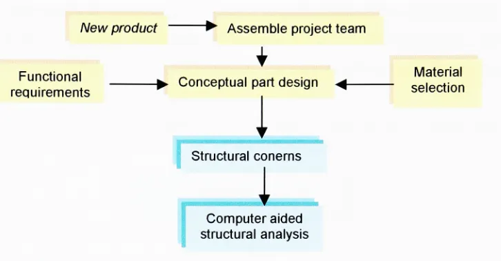
consideration.Newproduct ? Assembleprojectteam
Functional
requirements -?
Conceptual partdesign
^-1
Structural conerns
I
[image:13.520.75.438.179.368.2]Computeraided structural analysis
Fig. 4. Flowchart ofthesis methodology
Material
selection
Thesis methodology:
After
defining
functional requirements, proposing the material and process ofproduction, GECOS
bottle
dimensioning
canbe
proceeded, as one ofthe mostimportant
phaseinproductdevelopment
process.Whenthe GECOS
bottle
geometryis
completelydefined,
structural design analysiscan
be
performed, as checking whether thisbottle
geometry together with proposed materials canbarethepossibleloading
in
exploitation.Considering
comprehensiveness oftheanalysisfor
the complicatedGECOS bottle
3.1.
CONCEPT DEVELOPING
Concept
developing,
asthefirst
phasein
technological development process, startswith an
idea.
The
idea includes
theart component,to achieve nice and aestheticform,
andfrom
thisbeginning
theidea is
developed
into
a workable product.At
this point thereis
obviously
much tobe done
before
theidea become
an actual product. Thereis
still notenough
information
tomakedetermination
onhow GECOS bottle
shouldbe
built.Function analysis, which
GECOS bottle
mustsatisfy,is
thefirst
step inthe process.Based on such analysis, certain requirements can
be
established. Functional requirementscan
be divided
ongeneral andtechnological requirements.Synthesis
of requirementsinto
so called complex unitforms
the list ofrequirements.
Technological Requirements
r ? 1
Technical Requirements Social Requirements
Functionality
Manufacturability
-Society
Development - Health-Ergonomy
- Esthetic - Education-Ecology
-disposing
-recycling -security Economical Requirements [image:14.520.43.480.301.557.2]3.1.1.
FUNCTIONAL
REQUIREMENTS
Theentiretechnological
development
processbeginswitha complete andthoroughdefinition
ofthe product specifications and end-use requirements. This is thefirst stage ofdevelopment
and veryimportant because
the technological development of product isbased
onthesespecifications.Product
functional
requirements, act as central clearing point and vitalcommunication channelthroughwhichideasareassembled andevaluated.
Functionalrequirements:
The ultimate requirement ofanyproduct is thatit perform thefunction forwhichit is
designed.
Primary
function ofGECOS bottle is to store and transport liquids in fooddomain,
which are easy fusible in water, so thisbottle,
ones emptied can easily bewashed. Liquids in the
bottles
are from foodindustry,
such as mineral water,juices,
milk
-as
long
asthey
are not carbonated. Itis because
of square shape ofthebottle,
whichdoesn't allowbulging.
GECOS bottle is made of plastic.
Loading
requirements:Dimensional
bottle
stability must be ensured even on worstloading,
which can beanticipated
during
bottle exploitation. It is assumed that it is the time when GECOSbottle is
full,
packed and itis
placed onthe bottom ofthe palletduring
warehousingandtransport.
Environmental requirements:
Outer environmental conditions, onwhich GECOS
bottle is
likely
tobe
exposed, arehigh
humidity
and variationsin
temperaturesbetween+40C (inwarehouse andduring
transport)
to-20C (since cooling beverage inrefrigerator).Dimensional requirements:
Distance betweensunkcenters,which is equalto the cube side
length,
aswell as outerdiameterofconnectingelement
-closure,isthecritical
dimension.
GECOS bottleshould
be dimensioned in
suchwaythatits inner
volumeis
1 1.- It
is
desirable to get as higher cube and area effectivenessas
it is
possibleduring
Ecological
requirements:
-Ecological
requirements referto the material,assumingthatplasticformakingGECOSbottle
couldbe
recycled.Since
the construction ofGECOS bottle enable the easierkeeping
and collecting, the empty GECOSbottles
will not be disposeddaily
intorefuse,
but
will bedisposed
more rarely andin
greater quantities on separate disposallocations,
in order to enable their recycling, what means that the environmentalpollutionwillbe significantly less.
Socialrequirements:
GECOS
bottle is newdesigned,
so it will satisfyindustry
and market needs for newproduct.
Theclosure mustbeequippedwithsafetyring, asproofthatbottleswerenot opened.
GECOS bottleadditional using quality isperformed when it
is
emptyandbecomestheobjectof children'splay,which canbe composed inthree-dimensionalstructures, such
as
building
blocks. Inthis way it satisfies educational requirements. It is necessary tooffer enough different shapes of GECOS bottles to construct as more different
3.1.2.
MATERIAL SELECTION
In this phase materials and process which can produce GECOS bottle must be
selected.
Quality
ofdesign
solution ofGECOS bottle
directly
depends on characteristicsofpolymers as
design
materials and characteristics ofthe process for the production. Likewith any other material, product design in plastic must satisfy two basic requirements.
GECOS
bottle
must provide reliable end-usefunctionality,
and whiledesigning
thebottle,
manufactureinspecified material and specifiedprocess mustbetakenintoaccount.
Plastics are material of
design.
Plastics are available in almost indefinite range ofproperties, releasing them from the structural-design limitations imposed on metal and
glass. Basic truism of structural design is that the material and the process selected
profoundlyaffectthequalityand appearance oftheproduct.
[
3]
Considering
theliquids
in thebottles,
as well as requirements, two materials weretakeninto account. Firstmaterial
is
PET (PolyethyleneTerephthalate),
andthe second oneis FfDPE (High
Density
Polyethylene). Which ofthese two proposed materials would bebetterto use, from structuralpoint ofview,willbechecked
by
structuraldesignanalysis.In structuraldesign analysis modelAwouldbe ofPETmaterial, while model B of
HDPE.Bothmodelswouldhavethesamegeometryandwouldbe loaded inthesame way.
Increased popularity of PET containers
by
consumershas
called fordesign
innovations
by
the industry. PETcontainers are idealfor
bottling
water, softdrinks,
juices
and other food products. Some of the advantages of PET containers vis-a-vis other
packaging alternatives include:
flexibility
indesign,
superior clarity, easy tohandle,
shatterproof, pure, inert and
lightweight,
excellent barrier to moisture, oxygen, carbondioxide and aroma. Due to their extreme clarity (like glass), PET bottles are always
preferredforcarbonatedsoftdrinks andmineralwater.
PETpossestheexcellentbalance of properties andthe
degree
ofcristallinitysothatlevel of orientationinthe
finishing
product canbe
controlled.PET bottles are
fully
recyclable and usedbottles
canbe
crushed and recycledinto
materialsforre-use orused
for
makingtextiles,
carpets and other plasticitems.
The most significant application features of HDPE are easily processibility and
good moisture
barrier.
Itslow
oxygen-,hydrocarbon-,
and flavor-barrier properties limitsits use
for
some applications. The mostblow
molded HDPE containers are pigmented toimprove
appearance, although natural HDPEis
used for many packaging applicationsparticularly for food.
Clarity
ofHDPE ispoor, it is translucentin itsnatural stage and canbetintedwithanyopaque color.
3.1.3.
PROCESS
OF
PRODUCTION
Selection
ofthe processing method shouldtake place in the earlystages ofdesignprocess.
Since
PET and HDPE are selected for material which can satisfy most ofrequirements,production processwhich
is
compatiblewiththismaterialsis
blowmolding.Blow molding
is
a process fortheproduction ofhollowobjectsinwhich airis usedto expanda
hot
preform (or parison) againstafemalemold cavity. Common featureof allblow
molded articlesisbottle
having
anopeningmuch smallerthanthebody.[
4]
An
important feature is
the capability to provide very thin wall selections withrelatively
low
stress.PET istheresinthatcanbe
biaxially
orientedby
stretchblow moldingwith carefultemperature conditioning ofan injection molded preform, but for the smaller bottles the
resinis alsousedinthebasic injection blowmoldingprocess.
HDPE is the resin most common used in blow molding in both extrusion and
injectionblowmoldingprocesses.
3.1.4. CONCEPTUAL DESIGN
The
invention in its
essence consists of square bottle construction, which on itssides
has
sunkconnecting
places shapedto acceptthe closure as connecting element. Theclosure ispressed-inintotheconnectingplace ofboth GECOS bottles.
Several
ideas have
to be enquired and more than one model drawn before a clearmodel canbe
formulated.
First itis
necessarytodevelop
aset ofworking drawings. Whenthe general configuration is established, computer aided design
(CAD)
needs todevelop
complex curves and shapes representedintheapplication.
Mayor changes on GECOS bottle shape are made in cube corners and on corners
below the neck. Cube corners are not rounded as
they
were on drawings in patentapplication. Now
they
are with slanted edges, so the bottle looks as grind prism, toassociate on
ice
or diamond. GECOSbottles
basic form is prism which consists ofthreecubeswithslanted edgesconnected with partition channels.
Becauseofbetterstatic stabilitytheload
bearing
wall is designed bellowthebottlesneck, continuos through bottle height. On drawings in patent application the partition
channels stretches all over cross section.
On all cube surfaces there are sunkconnecting places assignedto accept closures.
This bottle has 14 sunkplaces, one onthe
top,
one onthebottom,
andone on each side of cubes.Ontheupper part there istriangular sunksurface, while onits outer cornerthere is
neck. The placement ofthe neck at the sides on the bottle makes the liquid pouring out
easier. The
top
oftheneckis
leveledwiththeuppersurface.Beside the basic function ofthe closure to close the
bottle,
it is also universalconnecting element. The closure is pressed-in into the connecting place ofthe bottles. In
orderto ensure a compactcoupling, theouter closure diameter is biggerthanthe diameter
ofthe connecting place. The outer diameter of closure
is
toothed with small elastic teethwhich enablethe necessarydeformation.
Closure has horizontal partition wall and thread is only on one internal side.
Internalclosure
thread,
as well as thethread onthe neck,is
not specified, which enabledpotential clienttosetup
his
owndimensions
depending
on machines and casts.Beside
basic
closure eachbottle has
additional ring as well, which enable greaternumber ofconnecting combinations,
but
static stabilityas well whenthe bottle is full andonthe pallet. Whenthe
bottle
isfull
andclosed, the closureis
higherthan thetop
bottlesurface, so it can carry over the whole
loading
on the bottle neck, so the bottle wouldbecome
static unstable. It is whytheadditional ringmustbeput ontop
surface connectingplace,whenthebottle is fullandonpallet. Theclosure and additionalringaretheninsame
level. The
dimensions
ofadditionalring arethesame astheclosurebutwithoutthread.Since
uniqueness ofthe construction enables connecting into three-dimensionalstructures and represents
interesting
toy
for children-creative didactics tool
(building
blocks),
itis
necessarytoofferto themarket various paletteofshapes. Forexample, bottleswith oneortwo
blocks,
depending
onrequiredvolume, ortriangleprism made ofone, twoor three parts. All these combinations must ensure dimension compatibility because of
connecting.
Fig. 6. Frontviewofthreepart squareGECOS Fig. 7. Frontview ofthreepart squareGECOS
bottle bottle
[image:22.520.48.228.117.559.2]38,5 38,5
A*
-t
| 16.83
8. 17
2^
[image:23.520.58.378.52.462.2]-^
Fig. 9.
Top
viewofsquare GECOS bottle033
Fig. 10. Closure
028
i
\ H r
i
ff
j
Fig. 8. Crosssectionandbottomviewofsquare
GECOS bottle
tJIM.iaMM!m.*Ulil^WWW!MIIMiriM!nilW ^JOJJEl&
'$***
^-tAfiila
_
ichangessavedinfile Hxboca'.bocal1mi1
Ertei b<KJ-groundco'.oir.siro<nof&BLSjD') ?
Eri bKfcaroundenlcr name or no|DDUX]
*Stat(S] ^1*S S1|]|2=
FSBCMVC-F/'g. 71 3D GECOS bottlemodel(printscreenfroml-DEAS software)
utmummim.mnmt.mwiiiiMimiMnwmi '. .ja_x|
USa* 13.-W
_J
!
' "
'""
T~-<=
^
>
*q.o# o
-15- SHITE
Model filechangessawedin fileH.Mjoca^bccall.mfl Hodelfilechangessavedinfile HxboceNbocal1nfl Warning Oynanicviewingandlocalshadingdisabled
(orpicturefilecreation Ll
3
BBS
a|a-t|j aigSi|J|H"""= fmcwc
F/g. 72. 3D GECOS bottlemodelwithclosure(printscreenfrom l-DEASsoftware)
^fl^1tiM^m^:UII^1lfffW^^^J!.|.y.|,4W^,
^jni^J
15- OHITE
[Modelfilechangessavedinfile 1 Model filechangessavedin file 1
L
Dynanic vievingandlocal shading disabled picturefilecreation
~3
A
^
Jl*l
4<iG&d'
JSIJ
a| I^JSS |ai-0*Se:
F5BCMVC-F/g. 73. Wireframeof3D GECOS bottlemodel(printscreenfrom l-DEAS software)
l&d5 ras.
3.2.
STRUCTURAL
DESIGN CONSIDERATIONS
GECOS bottle functional
requirementsinclude
dimensional stabilityandtheabilityto withstand
externally induced
service stress. It is necessary to evaluate structuralreliabilityof suggested
design
toensurethatGECOS bottlewould serve adequately.The goal of structural
design
processis
to generate GECOS bottlethatwill be ableto withstandthe
loads
that arelikely
to be encounteredduring
service. This must be donewithin the constraints
dictated
by
the material. Since it is not possible to quantify theloading
conditions with great certainty, structural design calculations willbe performed atloading
conditionsthatarethought torepresenttheworst casescenario.The purpose ofstructural design is achievement ofan acceptable probability that
designed structure would not fit for the use
for
which it is required, i.e. that it will notreachaLimit State.
[
5]
Since thisphilosophy is clearlythe goal ofthis thesis project, itcan be difficult to
predict the probability of failure for GECOS bottle design as the properties of plastic
materials are strong function ofboth services environment andmanufacturing conditions.
Twofactorsthat toalargeextent arebeyondthecompletecontrol.
3.2.1.
DESIGN
METHODOLOGY
Different
approachesto structuraldesign
problemscanbe
used:Design
by
experience- Design
by
experimental approachDesign usingananalytical approach
Inthis thesisproject will
be
used analytical approach[
5]
[
6] [
7 ].Structural
engineering relations allow us to estimate the stress that occur whenGECOS
bottle is
subject to mechanicalloading.
The results of such theoretical structural analysis provide soundbasis
on which design decisions can be made. An engineering analysis generates an estimation ofhow GECOS bottle can be expected to behave underloading,
since number of assumptions, as material characteristics, form regularity, andboundary
conditions,all ofwhich aresimplifications,mustbemade.Use of computer aided linear structural analysis techniques has improved the accuracy, interpretation and speed at which structural design evaluations can be accomplished.
FEA (Finite Element
Analysis)
is used inthis structural design analysis. In FEA a complex problem is broken down into series ofinterrelated sub-problems that are solvedby
computersupport.The first stage in FEA process is preprocessing. A 3D geometry ofthe GECOS bottleneedstobemodeledusing CAD (Computer Aided
Design)
system.It is necessarytosimplifythe geometry ofGECOS bottle for FEA. Finite element mesh madeup ofseries simple elementsinterconnectedat anodes,is superimposedinthisgeometry.
The number ofelements, or mesh
density
used in the analysis,depends
onfactors
such as the rate of change in strain at the particular area ofthebottle.
Exact solutiondepends on proper shape offinite element and exact mathematical
description
of straindivisionanddeformation inside finiteelement.
Boundary
or restraint conditions represent any movement restrictions that themodel should obey.
The
loading
is applied at the end ofpreprocessing. In this case only the staticloading
has beentakeninto consideration.The second step in applying the FEA method is solving the equations. Since
computer solves
hundreds
of equations simultaneously stress and deformation aregenerated asresult.
The
last
stepoftheFEA method consistsofresultsinterpretationandevaluation.By
analyzing theloading
and calculation of deformation and stress, it will becheckedwhichof proposed materialscan
be
used.3.2.2.
QUANTIFYING
THE DESIGN PROBLEM
In order to evaluate the structural characteristics of the
bottle,
structural designproblems must
be defined.
It is necessaryto specifynumber offactors
before starting withanytypeof structural calculations.Those
factors include:
partgeometry
typeofsupport orrestraint
loading
conditionsmaterialbehavior /mechanical properties
environmental conditions
safety factors.
Once these items have
been
quantified, we can perform series of designcalculations, examinethe results, modify
design,
recalculate and repeat designdetails
untildesiredresults are obtained.
3.2.2.1. PART
GEOMETRY
GECOS bottle has
very complex geometry. In order to predict the stresses anddeformation
that resultfrom
an anticipated serviceloading,
it is
necessaryto simplify thegeometryofthis
bottle.
It
is
assumedthat sunk onthe sides and on thebottom
ofGECOS bottle
wouldn'tinfluence
on output results.Only
sunk on thetop
ofthebottle
remained, since thereis
expectedto occur maximum
deformation.
Thesesimplificationshave
influencedgreat dealon
decreasing
thenumber of elementsin FEA.}t.IDEAS8: FSB CAD/CAMlab:jadrank
Fig. 14. Simplified 3D GECOS bottle model prepared for meshing (print screen from l-DEAS
software)
[image:30.520.37.484.253.582.2]3.2.2.2.
GENERATING
THE MESH
Chosen
shape offinite
elementis
triangle shell withlength
of 7,5 mm. Finiteelement
is
thinshell withthicknessof0,5
mmElements
are generated with givendensity
overthe entire bottle surfaces. Thenthenodes
belonging
to theelements are optimizedin
awaythatnotwonodes areplacedatthesame
location.
The
generated mesh mustbe
continuous.Totalnumber of generated nodes
is
6655.Total
number of generated elementsis 3322.
I-1I.IJU.M+, IJI.IIJ.'ilHMff.W'WJMIMMimmiM Jfilxl
4Q.{3#n
-Fig. 15. Finiteelement model- FEMofGECOS bottle (print
screenfrom l-DEAS software)
[image:31.520.37.485.257.586.2]3.2.2.3.
MATERIAL MECHANICAL PROPERTIES
The mechanical characteristics of material must be quantifiedbefore any structural
design
calculations canbe
carried out. Material characteristics such as massdensity,
modulus ofelasticityandPoissons ratio, areused in design equationsto evaluatethe stress
and
deformation
associated with GECOS bottles loading. In addition, these maximumstress estimations mustthen
be
comparedwithmaterial stress-strainbehaviorto determinewhetherthesevalues remain within acceptable limits forthematerial that willbe used for
GECOS bottle.
Unfortunately,
mechanical behavior ofplastic material is quite complexand
difficult
to characterize it completely. In stress and deformation calculations it wastaken the average values of material mechanical properties. The simplificationwas made
by
taking
thePETandHDPEasisotropic
materials, sothelinearanalysis canbe
made.Units Mechanicalproperties PET HDPE
p
Mg/mJ
Mass
density
1,36 0,95E N/rW Modulusofelasticity 2000 1000
V Poissons Ratio 0,3 0,3
<T
N/mm'
Compressionstrength 100 20
% Elongation 70 100
[image:32.520.67.454.315.442.2]T C Temp,range -70/230 -20/250
Table. 1 Averagevalues of material mechanical properties
[
8]
3.2.2.4. BOUNDARY
CONDITIONS
The
bottom
ofGECOS
bottle mustbe
supported tobare
the applied loading. Inorder to remain
in
equilibrium(i.e.
F=0),
balancing
forces
arethe reactionforces
atthesupports.
Support
conditions areidealized.
Reallife GECOS
bottlehas
support conditionsthat
differ from
theseidealized
cases to somedegree. Conditions
that reach the actualsupport condition are to
fix
thebottom
ofthebottle. Fixed
support condition ofbottom
plate prevents rotation aroundx,yand z axes and
displacement in
any direction.fflLi:
onsurtacsicreated
1 forcesonsurfacesoverwritten
1displacement restraintsonsurfacescreated
4 displacement restraintsonedgescreated
4 displacement restraintsonvertices-'points/locotions
r:
I
m
-_
^^^^
;
g)5tart||j^30[S||C^WMinV*gn32\oTd...||3JHASB:
FSBCAD/C-Fig. 16. Idealizedconditions of supportedbottomofGECOS bottle
[image:33.520.47.478.238.566.2]3.2.2.5. LOADING
CONDITIONS
Once
partgeometry and support conditionshave beenestablished, theloading
mustbe
defined
and transformed or quantified into aform
thatis
suitable for stress anddeformation
calculation.In orderto evaluate the structural characteristics of a
bottle, location,
magnitude,and type of
loading
must be quantified. It must be decided which types ofidealloading
would reachthe real
life
situation.GECOS bottles
are requiredtofunction
under variety ofdifferent end-useloading
conditions. It
is
thebest
to evaluate the stress anddeformation
associated withloading
conditions that are expectedto representthe "worst
loading
case conditions". Itshouldbe
evaluated
for
safety.GECOS bottle
is intended
for non-carbonatedliquids,
since thefilling
of suchliquid is made under atmospheric pressure, in
full
bottle above the level liquid isatmospheric pressure. The level ofliquid in full GECOS bottle is bellow the triangular
surface on the
top
ofthe bottle. Thetop
offull
GECOSbottle
above theliquid
will befilled
with air under atmospheric pressure. Since theload is
acting ontop
ofthebottle,
expected maximum
deformation
under theload
will occur ontop
of thebottle.
Inaccordance withthis theassumptionis toneglect
hydrostatic
pressure,because it
wouldn'thelp
indecreasing
the stress and deformation ofGECOS bottletop
surface. The structuraldesignanalysis willbemade onempty GECOS bottle.
It
is
assumption that "worst caseloading
condition"
appears while
bottles
arepacked onthe lowestrowonthepalletinwarehouseorintransport.
With software CAPE99 the most efficient way ofputting the
bottles
on standardEuro pallet, with dimensions 1200x800x144 mm,
has
been established. Condition ofputting the second package onthepallet
is
by
height,
while allthe combinationsby
rowsand columns are permitted. No overhang is allowed on the pallet.
Maximum
allowedheight
ofputting inonthepalletis
1.5 m,whilemaximum massis 1000 kg.
Secondary
package is defined as cardboardtray
with stretch wrapping. Inside thesecondary package putting
in
of6, 8,
10 or 12 GECOSbottles is
allowed.Condition
ofputting GECOSbottles insecond packageis
by
height.
Sol. No.
Bottle Arrangement
Primary
package- GECOS bottle Secondarypackage Cubbe
Eff.
Area
Eff.
L W H #
l
'ay
# rows#/tray
#/load L W H1 3L-2W-1H 77 77 240 25 5 6 750 231 154 240 82 93 3 5L-2W-1H 77 77 240 15 5 10 750 385 154 240 82 93 13 4L-2W-1H 77 77 240 17 5 8 680 308 154 240 75 84 15 6L-2W-1H 77 77 240 11 5 12 660 462 154 240 72 82
Table2. Solution Report
Product Name Product Code Datafile Name Solution Ref.
Cube Used Area Used Pallet type bottle_3s (15.03.) 1 C 82,3 % 92,6 % Euro
6 Bottle /
750 Bottle / Load
25 / Layer
5 Layer / Load
125 / Load
Bottle
Load
Outside Dimension
Length Width Height 77,0 77,0 240,0 mm
231,0 154,0 240,0 mm
1200,0 600,0 1350,0
We ight
Net Gross 1,000 1,050 Kg 6,300 6,300 Kg 787,500 812,500 Kg
Cube 1422 cm*3 8537 cm*3 1,30 m*3 Pad 240,0 154JO
!<$>!
390,0 77,0 240,0 77,0l.This is an example for the CAPE PACK'
99 User Guides
2.Issued on 1/1/99
3. Issued byQC Department
4.Approved by QC Hanager
5-Use from 1/1/99
[image:35.520.37.488.58.149.2]6. Valid until 31/12/99
Fig. 17. ReportfromCAPE99(bestsolution underNo.
1.)
[image:35.520.45.418.175.569.2]Solution
underNo.
1.(3Lx2WxlH)
gives thebest
cube(82%)
and area(93%)
effectiveness',
i.e.
thelargest
number ofbottles
on the pallet(750),
and with lowestnumber of
secondary
package per pallet(75). Onepallet consists of5rowsby
height.
Since bottle
volumeis
11,
it is
assumedthatliquid in
thebottleis
water ofdensity
of
1000
kg/m3.
The
mass of wateris
1kg
perbottle.
In suchcase,loading
ofbottles in first
row on pallet
is
4kg,
i.e.
40 N.Distribution
ofthisforce is indicated in
following
way:
-closure carries overthe
loading
ontheedge ofthebottle
neck, and sincethe neckis
by
the
bottle
angle,totalloading
is assumed 10 N. Inthiscaseloading
typeis
described asconcentrated at
line.
-additionalring carries overthe
loading
on ring sunk surface onthetop
bottle surface.In this case
loading
typeis described
asdistributed
over area and totalloading
is
assumed 30 N.
Point Location: 00 Model fliechanges
1 forcesonedgescreated
1 forcesaunsur<*cescreated
1 forcesansurfacesovBrvritton
00 0 0 file H.NbocaVbocallrati
Pick ForceonEdgej/TracboruonSurface) Pick FwceonEdBw*/Ti<fctononSurfaces[Done]
[image:36.520.46.478.318.645.2]Zl
-a8start||j ^|0%jl|jWci\WINNT\System32\oiid.,.|[{gl-OEASB: FSBCAD/C EH** 9*5
Fig. 18. Idealized
loading
conditions3.2.3.
RESULTS
rii.lJll.MH:IJMiJJ'IBIIWIM*MIMWWW*)lffli-Fig. 19. ResultsofstressonMODEL A
Maximumstressunder requested
loading
of40 Non modelAis:l,99E+04 mN/mm2
= 19,9 N/mm2. It
is
indicatedonthetop
ofthebottle,
just
by
the sunkedge on
top
surface,opposite ofthe bottle neck, as it is shownin Fig. 19. Maximumstressis
coloredin
red.Comparing
with values on colorbar it
can be seen the distribution ofstress
in
GECOSS bottle. Maximum stressis less
than compression strength of thematerial which
is
100N/mm2
for
the PET. It proves that model A will hold "predictedworst case scenario", i.e. that calculated stress
is
within tolerances and bottle is welldimensioned. Since the compression
loading
is takeninto
account, the stress that occurin
model can
be
compared withcompressionstrengthofmaterial. [image:37.520.43.479.87.405.2]LJUilfU.^iJilJ.MJj.lilllHDillllllHilllUiMffmiiWunf
Fig. 21. ResultsofstressonbottomofMODEL A
LJI!.IJ.LM^,IJ.l.HJll.|iimf|MWIWI!S!HMBnm7
Fig. 22. ResultsofstressonMODEL B
Maximumstressunderrequested
loading
of40 NonmodelB is:l,99E+04mN/mm2
= 19,9 N/mm2. Sincethe
geometryof modelB
is
the sameasgeometryofthe model
A,
as well as theboundary
conditions andloading,
also the distribution ofstress
is
equal, asit is
shownin
Fig. 22. Maximum stressin
model Bis
equal tocompression strength ofHDPE
is
20 N/mm2. It can be concluded that model B needsdimensionoptimization.
L,U,JH;.:lJi.,ij.i;|.B^Wra,;MwE!E
Jnl*lFig. 23. Resultsofstresson
top
ofMODEL B-JC.I-DLA5(l: I SB LAD/LAMlab: jadiankam:M:\boca\bocal jnjx]
Fig. 24. Resultsofstress onbottomofMODEL B
[image:40.520.45.467.390.699.2]tJa.ij.u.Mj.i.ij.i.ijjj^iJiiuMiijJi.ni.'iuimiHjmTiBinmr njxj
[image:41.520.44.479.53.368.2];Ustsresuftsdata forlocationson a resultsdisplay 4-Q.a& d
Fig. 25. Resultsofdisplacementon MODEL A
On model
A,
the greatestdisplacement
is 2,46 mm andit is located
between thebottle
neck and sunk ontop
surface, asit is
shown in Fig.26.,
where maximumdisplacement is
coloredin
red. Fig. 25.indicates
expecteddisplacement,
where meshmodelrepresentsstartingmodelbeforebottle
loading
(withoutdeformation). Until GECOSbottle is
on pallet,it is
clamped with otherbottles that are besideit,
but
that restrictionis
not predicted
in
boundary
condition and thatis
the reason why thisbottle
have slightlydeclining
because
offeccentricload.lJl]]MIMH;JHJI1mi.l.Ukt.|lJ.I.W!MBBIMWIIW
[image:42.520.48.474.53.369.2] [image:42.520.45.469.392.705.2]^jnlxl
|Generatesa report on selecteddisplayresufrs 4Q.0#n
Fig. 26. Resultsofdisplacementon
top
ofMODEL A4kI DFA5 R: FSB CAD/rAMl.ih:j.idrank. jDjxJ
Fig. 27. ResultsofdisplacementonbottomofMODELA
ESa,IJ.U:J4IJ.J.UJ,l.|iWBBjBWM!MiggI
Jn|x]Fig. 28. Resultsofdisplacementon MODELB
Maximum
deformation
occurringin
model B equals4,93
mm. Elongation as theamount of stretch
in
FtDPEis
100 %. Maximumdeformation
of model B is two timeshigher
then maximumdeformation
of modelA,
andit
canbe
concluded that model Bneedsthickerwalls.
MODEL
A
MODEL B
Max
stressin
N/mm2
20
20
Compression
strengthin N/mm2
100
20
Max
displacement
in
mm2,46
4,93
Elongation
of materialin
%
70
100
Table3. Results
[image:43.520.38.484.500.608.2]jh-.l-DLASo: r-su lad/lamlab: ladtankam:I l:\boea\bocal
Fig. 29. Resultsofdisplacementon
top
ofMODEL BFig. 30. ResultsofdisplacementonbottomofMODELB
[image:44.520.44.468.385.697.2]4. CONCLUSIONS
Model
formulation
and thecorresponding
calculations were performed with thefollowing
assumptions:-
Average
values of material mechanical characteristics were
taken,
withthe assumptionthatPETandHDPEare
isotropic
materials.In
idealized
boundary
conditionsthebottom
ofGECOS bottle is fixed.
It
is
assumed that themostintense
loading
caseis
whenthebottle is
inlowest
rowonpallet,
loaded
withfour
rowsfull
offilled bottles.
In structuraldesign
analyze onlythestatic
load is
takeninto
consideration.- Becausethe
non-carbonated
liquids
arefilled in bottles
under atmosphericpressure, theinternal
pressure above the levelofliquid
in fullbottle is
also atmospheric. The loadis
acting on
top
ofbottle,
and it is the place where maximum deformation is expected.Sincethe
hydrostatic
pressure canbeseparatedfromtheeffects causedby
loadappliedon the upper surface,
it
canbe
neglected. The structural design analysisis
made onempty bottle.
Geometry
simplification wereimplemented
thatmade possible reduction of simulationtime through
decreasing
thenumber offiniteelements,which were usedincalculation,yet withthe resultsprecisionkeptunchanged.
Twomodels
having
the same geometry, loadedwiththe same staticload,
and withthe same
boundary
conditions but made ofdifferent materials were considered. Model Awas made of PET and Model B was made of HDPE. The calculations of stress and
deformationaremadeon modelAand modelB.
The results obtained from calculations of stress and deformation are presented in
Table 3. Asthe consequence ofthe compression characterofload was
imposed,
the stress obtainedfrom
analysis can relativelybe
compared with compression strength of givenmaterials. As
it
can be seenthe maximum stress in case of model Ais five
times lowerthan compression strength ofPET. Since the elongation ofPET is
70%,
the maximumdeformation of2,46 mm is considered acceptable for thepresent purpose. The maximum
stress in case of model B is the same as compression strength ofHDPE. In addition the
maximum deformation occurring in case of model B equals 4,93 mm.
Therefore,
can beconcludedthatmodel
B,
needsdimensionoptimization.The model
A,
with wallthickness 0,5 mm, gives satisfactoryresults ofstress anddeformation,
hence it can be concluded that the model Ais
well dimensioned. Furthermore,it iscapable to withstand,with gooddimensionalstability, the
loads
thatarelikely
tobeencountered
during
service.Following
steps in thedevelopment
of GECOS bottle are to make non-linearanalyze, and with CAM (ComputerAided
Manufacturing)
systemto check apossibilitytomanufacturethat
bottle,
andtomaketheprototypesthatwillbeusedinthetesting.REFERENCES
[
1]
Raos &Catic
-Razvoj
presanih polimernihtvorevina,
(Development ofpolymerproducts), Zagreb 1992.
[
2]
Robert A.Malloy
-Plastic Part Design
for
InjectionMolding,
HanserPublishers,
Munich, Vienna,
NewYork,
1994[
3]
HandbookofPlastic MaterialsandTechnologies,
editor: Irvin I. Rubin[
4]
FundamentalsofPackaging
Technology,
W. Soroka[
5] Sidney Levy
& J.Harry
DuBois-Plastic Product Design
Engineering
Handbook,
Published
by
Van Nostrand ReinholdCompany,
NY 1977[
6]
Bruce C. Wendle- WhatEvery
Engineer Should Know AboutDEVELOPINGPLASTICS
PRODUCTS,
Marcel DeckkerInc.,
NY 1991[
7]
PaulA. Tres-Designing
Plastic PartsforAssembly,
4thEdition,
Hansen GardnerPublications
Inc.,
Munich2000[
8]
M.Nadj
- Polimernimaterijali,Zagreb 1991
[
9
]
JosephF.Hanlon,
HandbookofPackageEngineering,
McGraw-Hill BookCompany,
USA,
1984.[
10]
l-DEAS Tutorial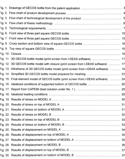
![Fig. 2. Flow chart ofproduct development process [1 ]](https://thumb-us.123doks.com/thumbv2/123dok_us/121620.11749/11.520.27.493.116.457/fig-flow-chart-ofproduct-development-process.webp)
![Fig. 3. Flow chart oftechnological development of the product[2]](https://thumb-us.123doks.com/thumbv2/123dok_us/121620.11749/12.520.33.490.198.598/fig-flow-chart-oftechnological-development-product.webp)