Abstract: During disturbances, the wind energy generation
apparatus are connected for stability improvement, to the grid. Distributed generation Grid failure, a major challenge particularly for PM synchronous wind turbines connected, back-to-back to converters and generator. The need of generated wind power grid integration protocol in terms of active and, reactive power control and failure travel (FRT) capacity needs to be discussed. Here a solution is presented which while fulfilling requirements of LVRT on grid failures, over voltage at dc – link suppression through improved BTB controllers, having a limit on active power, keeps the grid inverter peak current under safe limits during various asymmetric grid defect. By using the proportional and integral control loops, the inertia moment in the wind turbines will be reduced and dynamic performance can be improved. However, during the problem, the calculation time is more. Computational time is reduced by considering a proportional resonant controller and is implemented in the system, where by the active grid oscillation and dc - link voltage ripples are reduced. The validity and effectiveness of the proposed control approach were demonstrated in various conditions through simulation.
Index Terms: Back to back converter, Reactive power control,
Low-voltage ride-through, asymmetrical faults, symmetrical faults , voltage sag, active power control, peak current limitation.
I. INTRODUCTION
Wind energy is rapidly developing energy source in the world over, in light of fast depletion of fossil fuels [1]. The directly driven PMSG Wind Energy System (WES) having benefits of high precision, large power density, simple and easy control systems, is handicapped by high initial costs [2]-[4]. The WECS with variety of benefits is more importantly preferred to be grid connected. A few countries have recently published the protocols to connect the WES to the utility grid [3]. For efficiency, in the analysis of smart grid, micro grid, it was noticed that the micro grid voltage varies more than that of the utility grid. Improved control in the WES provides grid stability conditions. Solutions for the faults in the grid have been stated [4].For low voltage ride through (LVRT), on DFIG, an external resistor is placed in the circuit to absorb active power during the grid fault. The turbine operates continuously generating active energy while the reactive power is GSC controlled at the grid. [5]. However, GSC alone does mitigate the fault and in the case of a weak grid there is a danger of voltage instability [3]-[6]. A static synchronous compensator (STATCOM) was used for reactive power injection, and is installed at a common coupling point (PCC) grid facilitating uninterrupted functioning of the wind turbine.
Revised Manuscript Received on May 06, 2019
K.Keerthi, EEE department, AITS, Rajampet, A.P., India,.
P.B.Chennaiah, EEE Department, AITS, Rajampet, A.P., India
S.Sagar Reddy, EEE Department, AITS, Rajampet, A.P., India.
[7]. The rotor - side converter (RSC) is used only for ride - throwing DFIG capability, to protect against the rotor over current [7]-[9].
An alternate control strategy for PMSG wind turbine, with direct driven MW of high inertia is proposed. MPPT implemented through GSC and dc - link voltage, is controlled by MSC which eliminates active crowbar in dc - link. For positive and negative sequence components effects the dual current controller is designed. A new maximum current levels of all phases within the safety limit is proposed, for appropriate reactive current injection into the grid. In the grid voltage sag conditions, the limits for active and reactive GSC power refers are calculated with the PMSG excluded from MPPT while GSC is operated as STATCOM. The turbine - generator acts as energy storage. The increase in speed of the wind turbine is monitored through the pitch angle control, a strategy which is compatible with various grid protocols. The ripples on the grid side are suppressed using the proposed controller with the active power vibration and dc - link voltage.
II. SYSTEM MODELING
(A) Back-to Back Converter
In figure 1, the generator side converter works as a corrector and the grid side converter as an inverter [10]-[12]. the power flow is bi - directional.
Fig: 1. Back to Back converter
The grid side considered only in simulations, and hence back to back converter is not modelled. VSC grid side model to perform the simulations is adequate. The VSC includes a mechanical system making the time longer than the converter's switching time. Its logical scheme, one for voltage calculation and one for currents, have been implemented in two sub-blocks. The various BTB converters used in commercial WECS execute a conversion of the generator's variable voltage/frequency output to dc, dc to ac, with fixed voltage/frequency of the grid. As the power flow is bidirectional, SCIG, PMSG
and WRSG can use the BTB
converters. The BTB
A Superior Control Technique in Wind
Generation System under grid faults
converters, grouped according to the IEC 60038 standard - low voltage (< 1 kV) and medium voltage (1− 35 kV) converters, the classification is shown in figure 2. The popular voltages by many commercial wind turbine equipment manufacturers are 690 V and 575 V.
Fig: 2. Classification of back-to-back connected converters.
(B) Wind Energy Conversion System
Figure 3. gives the wind energy system consisting of a wind turbine to extracts wind energy, a PMSG, a BTB converter to transform variable frequency signals into grid frequencies as per the grid model.
Fig: 3. Simplified scheme of WECS.
GSC is joined to the common connection point (PCC) as shown above. A new strategy for control of PMSG - based direct - driven wind turbines, operating under various conditions is proposed. MPPT through GSC is implemented. The Dual Strom Controller deals with asymmetrical failures for GSC's positive and negative sequence components. An upper limit for the maximum currents of all phases within the safety limit is proposed, which deviates from other studies, while allowing the reactive current flow into the grid during symmetrical and asymmetrical grid failures, in line with the requirements of grid protocols.
III. SIMULATIONRESULTS
In Matlab / Simulink software many simulations have been performed and compared with the real conditions which demonstrate the good performance of the proposed method.
CASE A: UNSYMMETRICAL FAULT(L-G)
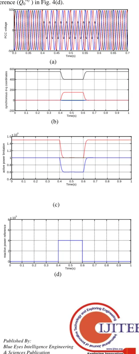
A L-G fault applied to PCC in 0.4 s. as in Fig. 4(a), resulted in voltage sag.. The PCC voltage was converted to d-q components, with positive- and negative-sequences separated as shown in Fig. 4(b). Fig. 4(c) shows the MPPT controller input as Plim , P0ref and Pgridref i.e. active power limitation, active power reference, and applied active power reference respectively. In Fig. 4(e) the d-q components of positive- and negative-sequences of GSC current with the active power limiter, Fig. 4(f) showing the voltage unbalance factor
equivalent to 0.3205 during voltage sag, Fig. 4(g), indicating the reactive current injection as per Danish grid code, Fig. 4(g) gives the ratio of Iq+ to Imax greater than rated GSC
current ratio (α), are depicted. Finally, dc-link voltage is shown in Fig. 4(h). New control strategy, demonstrates the dc-link voltage in safety range without any external devices, the amplitude of second-order harmonic fluctuations decreases. Fig. 4(i) shows the grid side current of the GSC. As shown, the peak of each phase current is kept within the safety limit. As mentioned before, to eliminate second-order component fluctuations of grid active power, Pc2 and Ps2 were
set to zero; therefore, the second-order component fluctuations of grid active power is removed (see Fig. 4(j)). But, the fluctuations of reactive power of grid are retained. Hence, the reactive power oscillates with 100 Hz as shown in Fig. 4(j). It is important to note that the average of reactive power in Fig. 4(j) is the same with the reactive power reference (Q0ref) in Fig. 4(d).
0.3 0.35 0.4 0.45 0.5 0.55 0.6 0.65 0.7 -500
0 500
Time(s)
PC
C
v
olt
age
(a)
0 0.1 0.2 0.3 0.4 0.5 0.6 0.7 0.8 0.9 1 -200
0 200 400 600
Time(s)
s
y
nc
hro
nou
s
d-q
c
oor
din
at
es
(b)
0 0.1 0.2 0.3 0.4 0.5 0.6 0.7 0.8 0.9 1 0.4
0.6 0.8 1 1.2 1.4 1.6x 10
6
Time(s)
ac
tiv
e
pow
er
lim
it
at
ion
(c)
0 0.1 0.2 0.3 0.4 0.5 0.6 0.7 0.8 0.9 1 0
2 4 6 8x 10
5
Time(s)
rea
c
tiv
e
pow
er
ref
ere
nc
e
[image:2.595.317.544.253.830.2] [image:2.595.66.269.335.398.2]0 0.1 0.2 0.3 0.4 0.5 0.6 0.7 0.8 0.9 1 -1000 -500 0 500 1000 1500 Time(s) + v e and -v e GSC c urre nt s (e)
0 0.1 0.2 0.3 0.4 0.5 0.6 0.7 0.8 0.9 1 -0.1 0 0.1 0.2 0.3 0.4 Time(s) v olt age unb ala nc e fac tor (f)
0 0.1 0.2 0.3 0.4 0.5 0.6 0.7 0.8 0.9 1
-0.2 0 0.2 0.4 0.6 0.8 1 1.2 Time(s) rea c tiv e pow er ref ere nc e fac tor (g)
0 0.1 0.2 0.3 0.4 0.5 0.6 0.7 0.8 0.9 1 1470 1480 1490 1500 1510 1520 Time(s) dc -link v olt age (h)
0.3 0.35 0.4 0.45 0.5 0.55 0.6 0.65 0.7
-2000 -1000 0 1000 2000 Time(s) Grid s ide c urre nt (i)
0 0.1 0.2 0.3 0.4 0.5 0.6 0.7 0.8 0.9 1 0 2 4 6 8 10 12x 10
5 Time(s) grid ac tiv e and rea c tiv e pow er (j)
Fig: 4(a) PCC voltage, (b) PCC voltage in the synchronous d-q coordinates, (c) active power limitation (Plim), active power reference (P0ref), applied
active power reference (Pgridref), and (d) reactive power reference. (e) the d-q
components of positive- and negative-sequences of GSC current, (f) the voltage unbalance factor (m), (g) reactive power reference factor (κ), the reactive current to rated GSC current ratio (Iq/Imax) and (α), and (h) dc-link voltage. (i) grid side current, (j) grid active power and grid reactive power in one-phase voltage sag.
In order to reduce computational time, a proportional resonant controller is implemented in the system.Use of the proposed controller can remove the active grid oscillation and dc - link voltage ripples as shown in figure 5.
0.3 0.35 0.4 0.45 0.5 0.55 0.6 0.65 0.7 -500 0 500 Time(s) PC C v olt age (a)
0 0.1 0.2 0.3 0.4 0.5 0.6 0.7 0.8 0.9 1 -200 0 200 400 600 Time(s) s y nc hro nou s d-q c oor din at es (b)
0 0.1 0.2 0.3 0.4 0.5 0.6 0.7 0.8 0.9 1 0.4 0.6 0.8 1 1.2 1.4 1.6x 10
6 Time(s) ac tiv e pow er (c)
0 0.1 0.2 0.3 0.4 0.5 0.6 0.7 0.8 0.9 1 0
2 4 6 8x 10
5 Time(s) rea c tiv e pow er ref ere nc e (d)
0 0.1 0.2 0.3 0.4 0.5 0.6 0.7 0.8 0.9 1 -1000 -500 0 500 1000 1500 Time(s) + v e a n d -v e s e q u e n c e s o f G S C c u rr e n t (e)
0 0.1 0.2 0.3 0.4 0.5 0.6 0.7 0.8 0.9 1
0 0.1 0.2 0.3 0.4 0.5 0.6 0.7 0.8 0.9 1 -0.5
0 0.5 1
Time(s)
rea
c
tiv
e
pow
er
ref
ere
nc
e
(g)
0 0.1 0.2 0.3 0.4 0.5 0.6 0.7 0.8 0.9 1 1470
1480 1490 1500 1510 1520
Time(s)
dc
-link
v
olt
age
(h)
0.3 0.35 0.4 0.45 0.5 0.55 0.6 0.65 0.7 -2000
-1000 0 1000 2000
Time(s)
Grid
s
ide
c
urre
nt
(i)
0 0.1 0.2 0.3 0.4 0.5 0.6 0.7 0.8 0.9 1 -5
0 5 10 15x 10
5
Time(s)
grid
ac
tiv
e
and
rea
c
tiv
e
pow
er
(j)
Fig: 5(a) PCC voltage, (b) PCC voltage in the synchronous d-q coordinates, (c) active power limitation (Plim), active power reference (P0ref), applied active power reference (Pgridref), and (d) reactive power reference. (e) the d-q
components of positive- and negative-sequences of GSC current, (f) the voltage unbalance factor (m), (g) reactive power reference factor (κ), the reactive current to rated GSC current ratio (Iq/Imax) and(α), and (h) dc-link voltage. (i) Grid side current, (j) grid active power and grid reactive power in one-phase voltage sag.
CASE B: SYMMETRICAL FAULT
On simulation of the symmetrical fault, as in Fig.6 (a), symmetrical voltage sag occurred 0.4 s which is more than 70%. As shown in Fig. 6(b), arising from the absence of a negative sequence component, α is equivalent with Iqf+ −/Imax,
and they are one. Also, reactive power reference factor κ is one. When this fault occurs, Plim approaches zero. Therefore, as shown in Fig. 6(c), Pgridref will be zero. Hence, the capacity of GSC is released and maximum reactive current will be injected to the grid. Fig. 6(e) shows the grid side current of GSC. All of the phase currents were retained in the safe limit. Also, Fig. 6(f) shows GSC current in the d-q reference frame. It is shown that the all capacity of GSC is occupied by positive sequence of reactive current in fault condition. The prevention of dc-link overvoltage is the main advantage of the proposed method as shown in Fig. 6(g).
0.3 0.35 0.4 0.45 0.5 0.55 0.6 0.65 0.7 -500
0 500
Time(s)
PC
C
v
olt
age
(a)
0 0.1 0.2 0.3 0.4 0.5 0.6 0.7 0.8 0.9 1 -0.5
0 0.5 1 1.5
Time(s)
rea
c
tiv
e
pow
er
(b)
0 0.1 0.2 0.3 0.4 0.5 0.6 0.7 0.8 0.9 1 -5
0 5 10 15 20x 10
5
Time(s)
ac
tiv
e
pow
er
(c)
0 0.1 0.2 0.3 0.4 0.5 0.6 0.7 0.8 0.9 1 -8
-6 -4 -2 0 2 4 6 8x 10
5
Time(s)
GSC
rea
c
tiv
e
pow
er
(d)
0.3 0.35 0.4 0.45 0.5 0.55 0.6 0.65 0.7
-2000 -1000 0 1000 2000
Time(s)
Grid
s
ide
c
urre
nt
(e)
0 0.1 0.2 0.3 0.4 0.5 0.6 0.7 0.8 0.9 1 -2000
-1000 0 1000 2000
Time(s)
d-q
c
om
pon
ent
s
of
GSC
c
urre
nt
0 0.1 0.2 0.3 0.4 0.5 0.6 0.7 0.8 0.9 1 1470
1480 1490 1500 1510 1520
Time(s)
dc
-link
v
olt
age
(g)
Fig:6(a) PCC voltage, (b) reactive power reference factor (κ) the reactive current to rated GSC current ratio (Iq/Imax) and (α), (c) active power limitation (Plim), active power reference (P0ref), applied active power reference (Pgridref), and (d) GSC reactive power in symmetrical fault. (e) Grid
side current, (f) the d-q components of positive- and negative-sequences of GSC current, and (g) dc-link voltage in symmetrical fault.
The results of the proportional resonant controller for this case is shown in figure 7 and this controller is used to reduce the computational time
0.3 0.35 0.4 0.45 0.5 0.55 0.6 0.65 0.7 -500
0 500
Time(s)
PC
C
v
olt
age
(a)
0 0.1 0.2 0.3 0.4 0.5 0.6 0.7 0.8 0.9 1 -0.5
0 0.5 1 1.5
Time(s)
rea
c
tiv
e
pow
er
(b)
0 0.1 0.2 0.3 0.4 0.5 0.6 0.7 0.8 0.9 1 -5
0 5 10 15 20x 10
5
Time(s)
ac
tiv
e
pow
er
(c)
0 0.1 0.2 0.3 0.4 0.5 0.6 0.7 0.8 0.9 1
0 2 4 6 8x 10
5
Time(s)
GSC
rea
ct
iv
e
pow
er
(d)
0.3 0.35 0.4 0.45 0.5 0.55 0.6 0.65 0.7
-2000 -1000 0 1000 2000
Time(s)
Grid
side
c
urre
nt
(e)
0 0.1 0.2 0.3 0.4 0.5 0.6 0.7 0.8 0.9 1 -2000
-1000 0 1000 2000
Time(s)
+
ve
a
n
d
-ve
se
q
u
e
n
ce
s
G
S
C
cu
rr
e
n
t
(f)
0 0.1 0.2 0.3 0.4 0.5 0.6 0.7 0.8 0.9 1 1470
1480 1490 1500 1510 1520
Time(s)
dc
-link
v
olt
age
(g)
Fig:7(a) PCC voltage, (b) reactive power reference factor (κ) the reactive current to rated GSC current ratio (Iq/Imax) and (α), (c) active power limitation (Plim), active power reference (P0ref), applied active power
reference (Pgrid ref), and (d) GSC reactive power in symmetrical fault. (e) Grid side current, (f) the d-q components of positive- and negative-sequences of GSC current, and (g) dc-link voltage in symmetrical fault
IV. CONCLUSION
It is successfully demonstrated that the ripples on the grid side can be suppressed using the proportional resonant controller with the active power control and dc - link voltage. This follows a reduction in computational time by the suppression of over voltages by dc-link through enhanced BTB converters .The design of an active power limiter is to keep the grid side inverter peak current safe during various faults conditions. A novel control strategy is suggested to improve fault ride through capability of permanent magnet synchronous generator based wind turbine.
REFERENCES
1. K.V.M.Reddy, Y.C.Saw and M.M.Choudhury, " An advanced control schemes for an synchronous generator based variable speed wind turbine", sustainable energy, Vol.3, p.p.143-150, Aug.2014.
2. C.Nagamai, G.S.Ilango and M.A.A.Rani, "An effective references generation schemes for wind generation with unbalanced grid voltage", sustainable energy, Vol.6, p.p.1433-1440, Jun.2014.
3. S.M.Fathi, J.Milinon, M.Nasiri, "An control LVRT enhancement schemes for PMSG base wind turbines," Renewable energy, Vol.36, p.p.399-408, Jun.2014B. Smith, “An approach to graphs of linear forms (Unpublished work style),” unpublished.
4. Z.Salan, K.Ishaque, "Optimal and direct control of PMSG based wing generation systems", Renewable & sustainable Energy reviews, Vol.19, pp.475-488, Mar.2013J. Wang, “Fundamentals of erbium-doped fiber amplifiers arrays (Periodical style—Submitted for publication),” IEEE J. Quantum Electron., submitted for publication.
5. B.A.Ramdan, A.Faheem Zobaa, "Control of PMSG based wind generation system to reduced damping oscillations", Sustainable energy, IEEE, Vol.8, Issue.2, April.2017.
6. C.Manickam, G.Raman,"A novel control strategy for VSC-HVDC connected offshore wind power plant", power electronics, IEEE, Vol.32, Issue.6, June.2017.
Author-1 Photo
8. E.Karatepe, S.Silvestre, K.M.Reddy, “Reactive power control in wind generation system to improve the system performance", solar energy, Vol.98, pp.322-334, Dec.2013.
9. G.Petrone, H.Renaudineau, “Modeling and control of a voltage support scheme in wind system during grid unbalanced conditions", Industrial Electronics, IEEE, Vol.62, Issue.2, Feb.2015.
10. Ritwik Majumder, Arindam Ghosh, Gerard Ledwich, Firuz Zare, Power Management and Power Flow Control With Back-to-Back Convertersin a Utility Connected Microgrid, IEEE Transactions On Power Systems, VOL. 25, NO. 2, MAY 2010.
11. Mojtaba Nasiri and Reza Mohammadi, Peak Current Limitation for Grid Side Inverter by Limited Active Power in PMSG-Based Wind Turbines During Different Grid Faults, IEEE Transactions On Sustainable Energy, Vol. 8, No. 1, January 2017.
AUTHORSPROFILE
K.Keerthi, received B. Tech in Electrical & Electronics Engineering from Vagdevi Institute of Technology and Sciences, Proddatur in 2016. At present she is pursuing M.Tech in Annamacharya Institute of Technology and sciences, Rajampet, Andhra Pradesh, India. Her research Interests are power system optimization and power electronics applications to renewable energy sources and Optimization techniques.
P.B.Chennaiah, received the B.Tech degree in Electrical and Electronics Engineering from JNTU college of Engineering, Anantapur, India, in 1998. He received M.Tech degree in 2007 from JNTU college of Engineering, Kukatpalli, Hyderabad, India, in the field of Electrical Power Engineering and Ph.D degree in the year 2017 from JNTUA. He is presently working as Associate Professor in the Department of Electrical and Electronics Engineering, AITS, Rajampet. His research interests are power system stability and control, voltage stability, FACTS devices, optimization techniques and evolutionary algorithms. He has published several research papers in various conferences and journals.