Design of a bilayer ceramic capacitor with low temperature coefficient of capacitance
P. Y. Foeller, J. S. Dean, I. M. Reaney, and D. C. Sinclair
Citation: Applied Physics Letters 109, 082904 (2016); doi: 10.1063/1.4961616
View online: http://dx.doi.org/10.1063/1.4961616
View Table of Contents: http://scitation.aip.org/content/aip/journal/apl/109/8?ver=pdfcov
Published by the AIP Publishing
Articles you may be interested in
Influence of temperature on the dielectric nonlinearity of BaTiO3-based multi-layer ceramic capacitors Appl. Phys. Lett. 108, 242902 (2016); 10.1063/1.4953626
Tuning of dielectric, pyroelectric and ferroelectric properties of 0.715Bi0.5Na0.5TiO3-0.065BaTiO3-0.22SrTiO3 ceramic by internal clamping
AIP Advances 5, 087145 (2015); 10.1063/1.4929328
Ferroelectric phase transition and low-temperature structure fluctuations in Ba 4 Nd 2 Ti 4 Nb 6 O 30 tungsten bronze ceramics
J. Appl. Phys. 105, 124110 (2009); 10.1063/1.3157147
( 1 − x ) Ba Ti O 3 − x ( Na 0.5 K 0.5 ) Nb O 3 ceramics for multilayer ceramic capacitors Appl. Phys. Lett. 90, 132905 (2007); 10.1063/1.2717559
Dielectric behavior and microstructure of ( Bi 1 ∕ 2 Na 1 ∕ 2 ) TiO 3 – ( Bi 1 ∕ 2 K 1 ∕ 2 ) TiO 3 – BaTiO 3 lead-free piezoelectric ceramics
Design of a bilayer ceramic capacitor with low temperature coefficient
of capacitance
P. Y.Foeller,a)J. S.Dean,I. M.Reaney,and D. C.Sinclair
Functional Materials and Devices Group, Department of Materials Science and Engineering, University of Sheffield, Sheffield S1 3JD, United Kingdom
(Received 28 June 2016; accepted 6 August 2016; published online 24 August 2016)
We show how a simple bilayer system that combines a layer of undoped BaTiO3(BT) with a second
layer of Ba0.975Na0.025Ti0.975Nb0.025O3 (2.5NNBT) can be used to improve the temperature
coefficient of capacitance (TCC) of BaTiO3-based materials for capacitor applications. The bilayer
system emulates the volume ratio between a conventional core and shell phase microstructure allowing a simple resource efficient approach to optimise the system for low TCC. Optimisation was achieved with a volume ratio of 0.67 2.5NNBT with 0.33 BT and results in a TCC of66% over the temperature range25 to 125C whilst maintaining a permittivity ofer3000 and low dielectric
loss. VC 2016 Author(s). All article content, except where otherwise noted, is licensed under a Creative Commons Attribution (CC BY) license (http://creativecommons.org/licenses/by/4.0/). [http://dx.doi.org/10.1063/1.4961616]
Multi-layer ceramic capacitors (MLCC) are essential com-ponents for consumer electronics with their global market exceeding 2 trillion units per year.1High permittivity and good temperature stability are two of the main factors for the ceramic capacitor industry. BaTiO3 (BT) is the current material of
choice for dielectric layers due to its high permittivity, excel-lent dielectric properties, and the ability to extensively modify the Curie temperature, TC at 120–130C, by appropriate
chemical doping of either or both of the cation sub-lattice sites. Its temperature dependent permittivity, referred to as the Temperature Coefficient of Capacitance (TCC), is modified with the use of such dopants2,3to achieve a TCC to meet indus-try standards, such as X7R (615% from55 to 125C).4
Commonly used dopants for BT are intermediate sized rare-earth (RE) trivalent ions, such as Y and Dy being used for both Ba and Ti sites.5–10Limited diffusion of the dopants into BT grains leads to a concentration gradient of doped BT resulting in a “core-shell-like structure” (CS).5,6,11–15 This structure can be considered to be a core-region of undoped BT (Tc120–130C) surrounded by a shell-region of micro volumes of different dopant concentrations, leading to a spread of Curie temperatures.12This approach engineers CS microstructures with a broad permittivity-temperature pro-file, reducing TCC to the levels required for industry stan-dard ratings. Inducing a CS microstructure requires an iterative approach which is resource intensive. Recently, Mauryaet al.adapted the concentration gradient of CS into a set of 70 layered doped compositions connected in either parallel or series.16The total capacitance of the series-type system was calculated using
1
Ctotal
¼Vr1
1
C1þVr2
1
C2; (1)
where Vris the volume ratio of a material, C is the capacitance
of a material, and Ctotalis the total capacitance of the series-type
system.
While this method has produced promising results, par-ticularly for the series configuration, each layer is individu-ally contacted to the electrodes. The overall permittivity will thus be dominated by the highest permittivity layer for the parallel set-up or the lowest permittivity layer for the series configuration (Fig.1).
To minimise TCC in this arrangement, many layers are required. Thus, the shrinkage rate during ceramic processing is constrained, and as such the compositional variation that can be used is limited. Precise control of the interfacial cou-pling is key, and with70 different compositions, this design approach is unattractive from a commercial viewpoint.
We have recently reported the use of finite element modelling to predict the required optimal volume fraction of a CS structure to obtain minimisation of the TCC response based on a combination of two materials. Minimisation of TCC was obtained by using experimentally determined permittivity (e)-T characteristics of undoped BT (core) and various compositions in a NaNbO3-BaTiO3 (NNBT) solid
[image:2.612.338.535.557.719.2]solution series (shell).17This led to the conclusion that com-bining 2.5NNBT with BT produced the most improved TCC
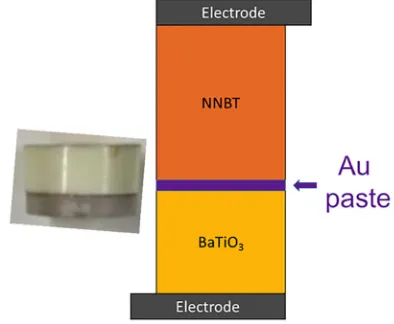
FIG. 1. Schematic and an example of a 2.5NNBT-BT bilayer ceramic in a series configuration.
a)Author to whom correspondence should be addressed. Electronic mail:
characteristics. In contrast to the multi-composition approach of Maurya’s, our design is based on only two compositions, one of which is undoped BT (Fig.1). This methodology is therefore more attractive since it is based on viable, high throughput ceramic processing routes.
x(NaNbO3)–(1-x)BaTiO3(2.5NNBT, x¼0.025) powder
was prepared via a solid state reaction. BaCO3 (99%,
Sigma-Aldrich, Dorset, UK), TiO2(99.9%, rutile,
Sigma-Aldrich, Dorset, UK), Na2CO3 (99.5%, Fisher Scientific,
Loughborough, UK), and Nb2O5 (99.999%, Stanford
Materials Corporation, USA) were used in appropriate quan-tities to produce a50 g stoichiometric batch. Each reagent was weighed to an accuracy of 60.001 g and the resulting mixture was ball-milled in iso-propanol using 10 mm diame-ter Y2O3-stabilized Zr milling media for 12 h. After milling,
the slurry was dried at 80C for 12 h.
The dried sample was sieved through a 250lm mesh sieve and the resulting powder reacted in an alumina crucible at 1140C for 6 h. Following this, the powder was ball-milled, dried, and sieved again. Green pellets with a 10 mm diameter were pressed in a uniaxial press at0.3 tonne for
1 min, then placed on Pt-foil in an alumina crucible, and sintered in air at 1400C for 8 h.
BaTiO3 powder was obtained from an industrial source
(AVX Ltd.) and pellets were pressed and sintered under the same conditions as 2.5NNBT. Lattice parameters for BT and 2.5NNBT from powder obtained from crushed sintered pellets were obtained by powder x-ray diffraction (XRD) using an X-ray diffractometer (PANalytical X’PERT3, Almelo, The Netherlands). Pellet density was obtained using the Archimedes method (MS-DNY-43, Mettler Toledo). Ceramics were polished and coated with Au-paste, which was fired on at 800C. The dielectric properties of the individual pellets and then the combined bilayer, using various inner electrode arrangements (described later), were measured using an LCR meter (Agilent E4980 Precision LCR Meter, Agilent Technologies) with an applied ac voltage of 100 mV. Data points were collected every 60 s from room temperature (RT) to 150C using a non-inductively wound tube furnace at a rate of 1C min1and corrected for sample geometry. Thermal expan-sion of the materials was determined by a DIL 402 C (Netzsch, Selb, Germany) with a heating rate of 5C/min and a tempera-ture range of 25 to 1400C. Scanning electron microscopy (SEM) was carried out on sintered pellets of 2.5 NNBT and BT. Pellets were initially polished with 800, 1200, and 2500 grit sili-con carbide paper, followed by 6, 3, and 1lm diamond polish pastes on synthetic polishing cloths. Following an acetone wash, they were thermally etched for 1 h at 90% of their sintering tem-perature. The etched pellets were mounted on aluminium stubs using silver paste (Agar Scientific Ltd., Stansted, UK) and coated with a conducting gold layer (EMSCOPE SC500A, Quorum Technologies, Laughton, UK). The samples were examined using an Inspect F50 FEG (FEI, Hillsboro, Oregon, USA) SEM operating at a spot size of 3.0lm and 20 kV.
To optimise the TCC in the bilayer system, we alter the thickness of the individual layers. To control the thickness, the amount of each powder required for a specific fraction was pre-determined using the equation below
d¼ vfq; (2)
where d is the mass of dielectric material required for correct thickness, vfthe volume fraction of the dielectric material,
and q the density of the ceramic after sintering at 1400C for 8 h. This amount was then adjusted to be as close to 1 g as feasible. The pellet dimensions were measured after pol-ishing and before the application of electrodes to ensure the relative thicknesses were within61% of the desired volume fraction.
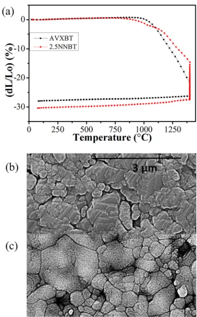
Ceramics were confirmed to be single-phase by XRD with lattice parameters, a¼3.9939(1) and c¼4.0375(1) A˚ for BT and a¼4.0027(1) and c¼4.0201(1) A˚ for 2.5 NNBT giving c/a ratios of 1.011 and 1.004 for BT and 2.5NNBT, respectively. BT has a higher shrinking onset temperature and finishes with a slightly smaller shrinkage compared to 2.5NNBT, Fig. 2(a). The sintering process results in dense ceramics, 98% for BT and 95% for 2.5NNBT as confirmed by SEM, Figs. 2(b)and2(c). The bilayers were constructed from undoped BT and 2.5 NNBT ceramics. The pellets were not co-sintered for this work; however, the dilatometry per-formed on the individual materials suggests that co-sintering could be feasible, Fig.2(a).
The permittivity versus temperature profiles for BT and 2.5 NNBT ceramics are shown in Fig. 3(a). BT has a room temperature (RT) permittivity of2500 which rises to a sharp maximum of 7100 at 126C (Curie Temperature, TC). In
contrast, 2.5 NNBT has a RT permittivity of3900 and has a broad permittivity maximum of 4800 at 60C with evidence of a secondary broad peak of 3500 at 110C.
FIG. 2. (a) Dilatometer profiles of green pellets for the individual compo-nents of the bilayers and SEM micrographs of sintered (b) BT and (c) 2.5NNBT ceramics.
[image:3.612.337.540.406.732.2]The corresponding TCC profiles were calculated using Equation(3), where
TCC¼ De e25DT
; (3)
the change in temperatureDT is relative to 25C and Deis the change in relative permittivity er relative to the value
obtained at 25C and denoted bye25.
The profiles in Fig.3(a)show the large variation of TCC for BT which is initially negative but becomes strongly posi-tive around TC, whereas 2.5 NNBT shows much lower TCC
that is initially positive but becomes strongly negative above
100C, Fig.3(b).
These two permittivity-temperature profiles were used as input data sets for optimisation. They were connected in a series arrangement with various thicknesses, and hence vol-ume fractions in an attempt to minmise TCC. The variations in permittivity and TCC for a two layer series-type system with various volume fractions of BT and 2.5 NNBT are shown in Figs.3(a)and3(b), respectively.
The simulations clearly show the strong suppression of the large permittivity and TCC of BT near TCas the volume
fraction of 2.5 NNBT increases in the series bilayer model. To simplify the optimisation, we employ a simple metric of the maximum deviation (absolute) of TCC from zero based on Fig. 3(b). The result of which is shown in Fig.3(c). This can be used to estimate the optimised volume fraction of 2.5 NNBT and BT to obtain the lowest TCC. The results indicate that bilayers based on vf0.6 to 0.7 of 2.5 NNBT
achieve the lowest TCC values.
To verify the prediction from the model, ceramics based on vf¼0.67 of 2.5 NNBT were prepared and connected
in series as described in the experimental section. The per-mittivity and tand profile of the bilayer are compared to those of its individual end member components in Fig. 4. This comparison shows the bilayer to have a permittivity of
3000 between 25 and 125C whilst retaining a low dielec-tric loss over the same temperature range. TCC of the bilayer compared to the end members is much improved, with TCC being as low as 66% over the temperature range of 25 to 125C.
Figure4(a)does show a difference in the absolute per-mittivity of predicted combination and experimental data because the model assumes a perfectly flat interface between the two layers. Experimentally this is not the case as each layer is not perfectly flat and there is a layer of gold paste between the components (Fig.5).
To confirm the effect(s) of interface roughness and possi-ble incomplete electrode coverage, different interfaces were created to examine their influence on the permittivity values of the system. Pellets for a 60/40 2.5NNBT/BT bilayer were created and their permittivity collected with three kinds of interface between the pellets; Au foil, Au paste, and nothing
FIG. 3. (a) Experimentally measured permittivity-temperature profiles of BT (filled black symbols) and 2.5NNBT (filled olive green symbols) ceramics with simulated permittivity-temperature data from the series bilayer model for various volume fractions, vf, e.g., 0.2(2.5)–0.8(BT)
corre-sponds to vf¼0.2 (2.5 NNBT) and vf¼0.8 (BT). (b) Converted TCC values
and (c) the maximum deviation of TCC versus vfof 2.5 NNBT.
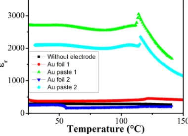
[image:4.612.70.276.52.442.2] [image:4.612.332.540.461.744.2]in-between the pellets. In the case of Au paste, two interfaces were fabricated. Au paste 1 interface was achieved by first coating the individual pellets with paste that was hardened and the pellets subsequently compressed together during measurements. Au paste 2 interface was achieved by a coat of paste between the two ceramics that was subsequently hard-ened to bond the two ceramics together. In the case of gold foil, a piece of gold was placed between the ceramics and the pellets subsequently compressed together during measure-ments. This arrangement was repeated twice (Au foil 1 and 2). The change in permittivity for the different interfaces is shown in Fig. 6. The permittivity drops significantly when there is no inner electrode or when the Au electrode interface is created from either Au foil or Au paste 2. This highlights the importance of the electrode interface in the performance of the device and the need to achieve good interfacial contact between the pellets to obtain a high permittivity bi-layer ceramic. The poor internal electrode contacts are due to a combination of incomplete (or no) electrode coverage and surface roughness at the interface between the ceramics.
Although it is not a focal point of this study, the choice of compatible internal electrodes with the bilayer materials for any MLCC application is an important consideration. In the case here, the choice of NNBT which contains Na (and in the absence of any other dopants) may restrict the choice of internal electrode materials to Ag/Pd and Pt based on air sintering as opposed to base metal electrodes such as Ni that require sintering under reducing conditions. Further
compatibility/processing studies are required to confirm this suggestion.
TCC has been successfully improved by creating a novel bilayer-system of 2.5NNBT and BT ceramics. The demon-strated methodology allows for optimisation of many different materials and the creation of a system with a permittivity of
3000, low dielectric loss, and a TCC of66% over the range 25 to 125C, based on a volume ratio of 0.67 2.5NNBT to 0.33BT. Furthermore, it was shown that the interface between the layers exerts a significant influence on the permittivity, making it important to control the electrode interface between the ceramics. Further work is required as it is important to account for and potentially optimise the sub-ambient tempera-ture region to achieve commercially popular specifications, e.g., X7R down to55C, as well as to further understand the interface(s) between the ceramic layers.
We thank the EPSRC (EP/L017563/1) for funding and AVX Ltd. for providing the BT powder.
1
J. Ho, T. R. Jow, and S. Boggs, “Historical introduction to capacitor tech-nology,”IEEE Electr. Insul. Mag.26, 20–25 (2010).
2
D. Hennings, A. Schnell, and G. Simon, “Diffuse ferroelectric phase tran-sitions in Ba(Ti1yZry)O3 ceramics,”J. Am. Ceram. Soc. 65, 539–544
(1982).
3
H. Kishi, Y. Mizuno, and H. Chazono, “Base-metal electrode-multilayer ceramic capacitors: Past, present and future perspectives,” Jpn. J. Appl. Phys., Part 142, 1 (2003).
4See http://www.murata.com//media/webrenewal/support/library/catalog/
products/capacitor/mlcc/c02e.ashx?la¼en-usfor Murata – Chip Monolithic Ceramic Capacitors.
5
C.-H. Kim, K.-J. Park, Y.-J. Yoon, M.-H. Hong, J.-O. Hong, and K.-H. Hur, “Role of yttrium and magnesium in the formation of core–shell structure of BaTiO3grains in MLCC,”J. Eur. Ceram. Soc.28, 1213–1219 (2008). 6C.-C. Chou, C.-S. Chen, I. N. Lin, W.-C. Yang, and H.-F. Cheng,
“Development of X7R type base-metal-electroded BaTiO3capacitor
materi-als by Co-doping of MgO/Y2O3additives,”Ferroelectrics332, 35–39 (2006). 7
J. Nishikawa, T. Hagiwara, K. Kobayashi, Y. Mizuno, and H. Kishi, “Effects of microstructure on the Curie temperature in BaTiO3-Ho2O3
-MgO-SiO2system,”Jpn. J. Appl. Phys., Part 146, 6999–7004 (2007). 8
H. Kishi, N. Kohzu, J. Sugino, H. Ohsato, Y. Iguchi, and T. Okuda, “The effect of rare-earth (La, Sm, Dy, Ho and Er) and Mg on the microstructure in BaTiO3,”J. Eur. Ceram. Soc.19, 1043–1046 (1999).
9D. Makovec, Z. Samardzija, and M. Drofenik, “Solid solubility of
hol-mium, yttrium, and dysprosium in BaTiO3,” J. Am. Ceram. Soc. 87,
1324–1329 (2004).
10
K.-J. Park, C.-H. Kim, Y.-J. Yoon, S.-M. Song, Y.-T. Kim, and K.-H. Hur, “Doping behaviors of dysprosium, yttrium and holmium in BaTiO3
ceram-ics,”J. Eur. Ceram. Soc.29, 1735–1741 (2009).
11
Z. Tian, X. Wang, H. Gong, T.-H. Song, K. H. Hur, and L. Liz, “Core–shell structure in nanocrystalline modified BaTiO3 dielectric
ceramics prepared by different sintering methods,”J. Am. Ceram. Soc.94, 973–977 (2011).
12C. A. Randall, S. F. Wang, D. Laubscher, J. P. Dougherty, and W.
Huebner, “Structure property relationships in core-shell BaTiO3-LiF
ceramics,”J. Mater. Res.8, 871–879 (1993).
13
M. J. Pan and C. A. Randall, “A brief introduction to ceramic capacitors,” IEEE Electr. Insul. Mag.26, 44–50 (2010).
14H. Y. Lu, J. S. Bow, and W. H. Deng, “Core–shell structures in ZrO 2
-mod-ified BaTiO3ceramic,”J. Am. Ceram. Soc.73, 3562–3568 (1990). 15
S.-C. Jeon, C.-S. Lee, and S.-J. L. Kang, “The mechanism of core/shell structure formation during sintering of BaTiO3-based ceramics,”J. Am.
Ceram. Soc.95, 2435–2438 (2012).
16D. Maurya1, F.-C. Sun, S. P. Alpay, and S. Priya, “A new method for
achieving enhanced dielectric response over a wide temperature range,” Sci. Rep.5, 15144 (2015).
17
J. S. Dean, P. Y. Foeller, I. M. Reaney, and D. C. Sinclair, “A resource efficient design strategy to optimise the temperature coefficient of capaci-tance of BaTiO3-based ceramics using finite element modelling,”J. Mater.
[image:5.612.70.276.53.207.2]Chem. A4, 6896–6901 (2016). FIG. 6. Permittivity profiles for different interfaces between the ceramic
[image:5.612.79.269.602.740.2]layers.
FIG. 5. A comparison of modelled and experimentally obtained TCC pro-files for a bilayer BT-based ceramic based on vf¼0.67 2.5NNBT.