PC-BASED VISUAL SIMULATION OF HIGH
PRESSURE ARC PLASMA
A THESIS SUBMITTED TO THE UNIVERSITY OF LIVERPOOL FOR
THE DEGREE OF DOCTOR OF PHILOSOPHY IN THE FACULTY OF
SCIENCE AND ENGINEERING
By
Yiyi ZHAN
BSc (Guangdong), MSc (Liverpool), AMInstP
Plasma and Complex Systems Research GroupDepartment of Electrical Engineering and Electronics
University of Liverpool
First Supervisor – Dr Joseph D. YAN
Second Supervisor – Professor Joseph W. SPENCER
ABSTRACT
The work in this thesis is concerned with the visual simulation of high pressure arc plasmas in two different applications. The first one is an arc maintained in water for the formation of nano-structures such as nanotubes and fullerenes. The second application is high power switching using puffer circuit breakers. The fundamental behaviour of both arc plasmas was computationally studied.
The structure of the thesis starts with an introduction to the background and objectives of the present work, the arc models used for the two applications are described in Chapter 2 together with a consideration of the radiation and turbulence models, material properties initial and boundary conditions, and issues relating to solution procedures. Chapter 3 is devoted to the modelling of the carbon plasma in water taking into account size of gas bubble growth, water evaporation and chemical reactions in the gas. Chapter 4 presents the computational simulation of the whole arcing process of a high voltage puffer circuit breaker where predicted arc voltage and pressure evolution in the storage volume are compared with the test results. Modelling of the current zero period and the calculation of the critical RRRV is also included. The proposed method for object based visual simulation is described in Chapter 5. Finally conclusions are drawn in Chapter 6 together with a discussion of the future work.
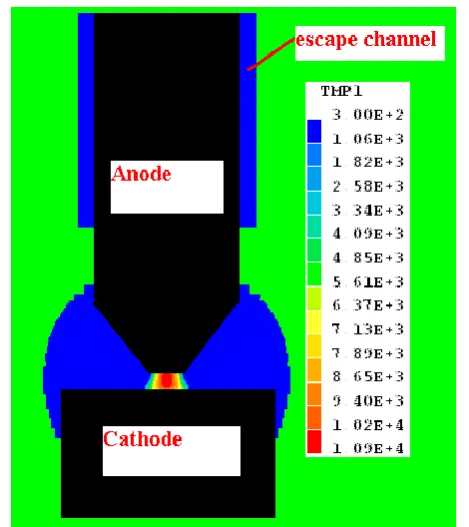
For the arc in water case, it is the first time that an arc model is applied to study the carbon arc confined in water considering chemical reactions of water vapour and carbon vapour. The arc is generated between two carbon electrodes which are immersed in water with a gap length of 1 mm. The anode has a conical shape with a rod diameter of 8.2 mm and a tip diameter of 2 mm with a full conical angle of 60o. The anode has a cylindrical shape with a diameter of 12 mm. A local thermal equilibrium arc model was used to tackle the problem based without considering the sheath layer in front of the electrodes. The loss of carbon vapour due to formation of solid carbon structures is represented by a negative volumetric source. The erosion rate of the anode is derived from experimental result.
Results show that the strong influx of carbon vapour displaced the original water vapour in the gap in a few microseconds, typically 5 µs. By 4 ms the arc burns in a carbon dominated environment with about 25% of water vapour in the region near the cathode. Our results thus suggest that for most of the time the arc can be regarded as burning in a carbon vapour dominated environment.
Reaction rate coefficient between carbon vapour and water vapour was derived from that at low temperature (300 K) using the well known Arrhenius expression. The value of this coefficient is 1.054×10⁶. It has been found that the mass concentration of H2 and CO peaks in a layer surrounding the arc column. The maximum concentration is only 0.2% and
surrounding gaseous environment since the erosion rate of carbon anode (6×10 kg/s) is still much lower than the water evaporation rate (6×10⁻⁵ kg/s).
The predicted voltage of the arc column at 30 A is 7 V while the measured arc voltage including the sheaths is 17 – 20 V. The difference is attributed mainly to the exclusion of the electrode sheath model in the present work. Considering that the first ionisation energy of carbon vapour at ground state which is 11.26 eV, the predicted voltage of the arc column is well placed in the expected range.
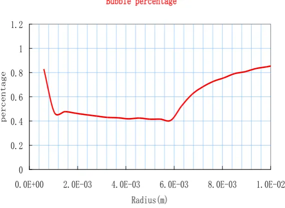
A numerical scheme has been established in the present work to simulate the growth of gas bubble confined in water. The position change of the interface of the bubble-water is controlled by the pressure difference between that inside the bubble and the atmospheric pressure. The inertia of the water surrounding the bubble is taken into account in the construction of the dynamic response. Our results show that the growth of the bubble is dominated in the first half millisecond by the retreat of the water surface as a result of evaporation. Further on in the arcing process, the pressure difference makes a dominant contribution in the growth of the bubble.
For the switching arc case, the arcing process for four test duties of a 252 kV puffer circuit breaker has been simulated. A novel method was proposed to improve the arc voltage prediction by mitigating the effect of Lorentz force near the tips of hollow contacts and their filling transparent contacts. The proposal of this method is based on consideration of the most probable practical scenario in reality. Results present in the thesis show that this method is effective and gives satisfactory arc voltage prediction for all four test cases at different current levels and arc durations. As an example the arc voltage in the 47 kA case at 16.8 ms with an instantaneous current of 55 kA is 220 V, almost the same as that of the measurement while without using the method the prediction is 340 V.
Turbulence is important in the interruption process of high voltage SF6 circuit breakers. It has been found that Prandtl mixing length model with a constant turbulence parameter is not able to predict the important extinction peak in the puffer circuit breaker. In the present work this turbulence parameter is made variable, as a function of instantaneous current that is an indirect measure of the presence of cold SF6 flow around the arc column. The modified turbulence model was then applied to simulated the current zero period (from 15 kA before final current zero onwards to the current zero point) of a 47 kA case and a 10 kA case. The predicted arc voltage using the modified turbulence model starts to increase rapidly shortly before the final current zero point, qualitatively agree with the measurement. A detailed comparison is not sensible since the accuracy of the measurement is not known.
represented and discussed.
The thermal interruption capability of a circuit breaker is represented by the critical RRRV, a value of the rate of rise of recovery voltage that the circuit breaker can with stands. Procedures were set up and some example results reported in the thesis. Accurate prediction of the critical RRRV is not possible at present. Nevertheless, the established procedure for the calculation of the post arc current under the influence of system recovery voltage can be of help in studying the behaviour response of a circuit breaker when a design parameter is changed. The shift of the critical RRRV in response to a design parameter change gives an indication of the effectiveness of the change in design.
Computer simulation of electric arcs for industrial devices proves a difficult job in the sense that much coding and setting is required to implement the arc in a chosen software package. An approach has proposed to use Object oriented programming to change the model setup from manually to automatic. The feasibility of the approach has been demonstrated in the present work by a component builder and a Visual Analyser and Monitor (VCM). Information exchange between ISEE and the CFD solver is through memory sharing. Typical results for visual simulation are given in Chapter 2, demonstrating a range of useful functionalities it provides and the benefits for arc modellers.
ACKNOWLEDGEMENTS
TABLE OF CONTENTS
Chapter 1 – Introduction - 1 -
1.1 Atmospheric Arc Plasmas - 1 -
1.2 Brief history of plasma research and applications with particular reference to arc
plasmas - 2 -
1.2.1 Background of arc plasma applications - 2 -
1.2.2 The motivation of the proposed research work on arc in water - 3 -
1.3 Switching arcs and their modeling - 4 -
1.3.1 SF6 based circuit breakers - 4 -
1.3.2 Electric arcs as switching medium and the necessity of arc modelling - 7 -
1.4 Review of arc models - 7 -
1.4.1 The Black Box Model - 8 -
1.4.2 The Integral Model - 9 -
1.4.3 Two and Three Dimensional Full Differential Models - 11 -
1.5 Carbon arc for Formation of Nanostructures - 14 -
1.5.1 Nanotechnology and Formation of Nanostructures - 14 -
1.5.2 Carbon arcs in Liquid and Gaseous environment - 15 -
1.6 The Objectives of Research and Organization of Thesis - 18 -
1.6.1 Water plasma - 18 -
1.6.2 Switching arcs - 19 -
1.6.3 Object based visual simulation - 19 -
1.7 Reference - 20 -
2.2.1 SF6 Circuit breaker arcs - 32 -
2.2.2 Arc in Water - 36 -
2.3 Calculation of the Electric and Magnetic Fields - 38 -
2.4 Subsidiary Models - 40 -
2.4.1 Radiation Model - 40 -
2.4.2 PTFE ablation Models for Puffer Circuit Breaker - 45 -
2.5 Turbulence Models - 46 -
2.5.1 Modification to Prandtl mixing length model - 47 -
2.5.2 Modification to the k-epsilon Model - 61 -
2.6 Initial/Boundary Conditions and Special Sources - 67 -
2.7 An Integrated Simulation and Evaluation Environment for Switching Arcs - 68 -
2.7.1 Overall Structure of ISEE - 68 -
2.7.2 Visual Model Builder - 70 -
2.8 Summary - 81 -
2.9 References - 82 -
Chapter 3 - Computer Simulation of a Carbon Arc Confined in Water - 86 -
3.1 Introduction - 86 -
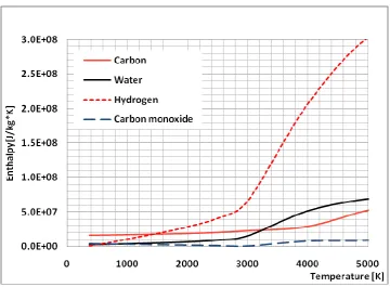
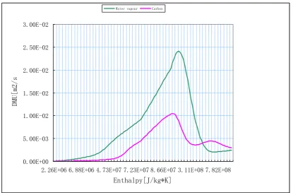
3.2 Material Properties and Chemical Reaction Rate - 87 -
3.3 Initial and Boundary Conditions and Loss of Carbon due to Formation of Carbon
Nano-structures - 93 -
3.4 Grid System and numerical Scheme for Bubble Growth - 97 -
3.4.1 The grid system - 97 -
3.4.2 Water displacement due to pressure difference - 98 -
3.4.3 Bubble Growth Due To Water Evaporation - 100 -
3.5.2 Development of arc column and transport of carbon species - 105 -
3.5.3 Characteristics of the arc - 110 -
3.6 Summary - 113 -
3.7 References - 114 -
Chapter 4 - Computer Simulation of the Arcing Process in a Puffer Circuit Breaker - 115 -
4.1 Introduction - 115 -
4.2 Test Conditions and Available Results - 116 -
4.2.1 Calibration and synchronisation of measurement - 116 -
4.2.2 Basic features of measurement: average electric field inside arc column - 119 -
4.2.3 Basic features of measurement: extinction peak - 121 -
4.3 Modelling of Arc Root near Hollow Contacts - 126 -
4.4 Grid system, Initial and Boundary Conditions - 132 -
4.5 Typical Results and Discussion - 135 -
4.5.1 No-Load Simulation - 135 -
4.5.2 High Current Phase - 146 -
4.5.3 Current Zero Period - 152 -
4.5.4 Post Arc Period - 155 -
4.6 Summary - 159 -
4.7 References - 160 -
Chapter 5 - Summary and Future Work - 161 -
5.1 Arcs Maintained in Water - 161 -
5.2 Arcs in Puffer Circuit Breakers - 163 -
5.4.2 Circuit Breaker arc - 166 -
Chapter 1 -
Introduction
1.1
Atmospheric Arc Plasmas
An ionised gas is known as plasma if its Debye length is much smaller than the
characteristic length of the system. For such a system charge quasi-neutrality holds.
Plasma is commonly known as the fourth state of matter.
Plasma in general consists of electrons, positive and negative ions, atoms and molecules.
Depending on the discharge conditions, plasmas can be broadly classified as those in
local thermal equilibrium (also known as thermal plasmas or plasma in LTE [Bou94])
and non-equilibrium plasmas. Under certain discharge conditions, usually for pressure
at atmospheric or above, the constituent species of the plasma attain the same
temperature. When this condition is satisfied the plasma is in LTE.
Arc discharges usually refer to those discharges at atmospheric pressure or above,
which are maintained by a current between two electrodes. Arc discharge is
characterised by low voltage drop in the cathode region and large current density at the
cathode. The plasma column between cathode and anode regions is usually in LTE and
is often simply referred as arc. In common with all LTE plasmas the properties of an arc
are determined by two thermodynamic quantities (e.g. temperature and pressure) and
the distribution of particles among available energy levels obeys Boltzmann‟s
distribution. The behaviour of an LTE plasma can be described by conservation of mass,
momentum and energy together with the equation of state, the laws governing
electromagnetic fields, charge transport (Ohm‟s law) and supplementary relations for
transport properties (i.e. electrical conductivity, viscosity etc.).
The present work is aimed at the establishment of appropriate mathematical models and
obtaining detailed computational results for the plasma environment in two systems
(hereafter referred to as carbon arc) surrounded by water and the other an arc in a high
voltage circuit breaker. The two topics represent the two areas for which Liverpool
University has expertise. Both applications involve moving boundary and the processes
are transient.
In this chapter, a brief history of plasma research is given in Section 1.2 which is
followed by a review of literature on switching arc modelling. In section 1.4 we discuss
the important aspects of carbon arc and its application related to nanotechnology and
finally the scope of investigation and organisation of the thesis will be given.
1.2
Brief history of plasma research and applications with particular
reference to arc plasmas
1.2.1 Background of arc plasma applications
The discovery of arc discharges at the turn of the 19th century can be regarded as the
beginning of the study of man-made plasmas. Up to the Second World War, little was
known about the fundamental processes occurring in plasmas. The discovery of nuclear
fusion and the subsequent realisation of the potential of controlled thermal nuclear
fusion promoted intense research activities in basic plasma physics during and
immediately after the war [Sim59]. The basic equations describing the behaviour of
plasmas ranging from collisionless to collision dominated plasmas were formulated. In
parallel with the development of basic plasma theory, diagnostic techniques, especially
after the invention of the lasers, have been developed to such an extent that the
measurement of basic plasma parameters has become common.
Arc plasmas are characterised by their high temperature and high energy density/flux,
which is ideal for certain technical applications such as light sources, material welding
and cutting and surface spraying. More recently arc plasmas have been used for
decomposition (waste disposal), deposition (thermal plasma chemical vapour deposition)
and synthesis of new materials (in the nanometer scale range) through plasma
1.2.2 The motivation of the proposed research work on arc in water
In these systems, the plasma is often generated and maintained either in high frequency
electromagnetic fields or between two electrodes with a DC or AC voltage applied. The
efficiency and stability of such systems critically depends on the plasma behaviour
under specified working conditions and the interaction between the plasma and work
piece or the material being processed. For the carbon arc in water, diagnosis of the
plasma parameters is extremely difficult because of the small electrode gap surrounded
by a volume of water. However to correlate the working conditions with the yield of
the system and to subsequently improve the design, fundamental knowledge of plasma
behaviour is essential. This inevitably requires the establishment of good physical
models and simulation of the arcing process for detailed information within the plasma
environment because of the complexity and difficulties involved. There have not been
many publications that simulate the plasma environment in a water plasma system
because of the complexity and difficulties involved. The problem is multi-disciplinary
in that processes at microscopic atomic and molecular level are closely coupled with
plasma motion under the influence pressure field and electromagnetic fields. Intense
interaction between plasma and its surroundings causes additional difficulty in gaining
an understanding of such discharges. The production the nanostructures is not the main
concern in the present work. The focus is on the fundamental characteristics of the
electric arcs and its interaction with the gaseous and liquid water.
The arc model for arc in water can also be applied to other applications such as arc in oil.
This is because the gaseous environment in both cases is formed as a result of
vaporisation of liquid, whether water or not. However the material properties of the
arcing gas are different. So the thermodynamic and transport properties of the vapour
supporting the arc must be used to obtain correct results. Different materials of the
electrodes will have different erosion characteristics when they interact with the arc.
The difference will be reflected in model parameters such as the total energy required to
1.3
Switching arcs and their modelling
1.3.1 SF6 based circuit breakers
Circuit breakers are used for normal switching operations and for interrupt a fault
current in a power system. Upon the separation of two contacts in a breaker an electrical
arc is drawn between two contacts. The design of a breaker ensures that the arc is
extinguished after passing a current zero. The presence of an arc in a breaker is
desirable in that excessive over voltage can be avoided as the fault current is interrupted
around current zero. Modern circuit breakers are of two types: vacuum circuit breakers
where the arc burns in the metal vapour supplied by the electrodes and gas filled circuit
breakers. For the latter SF6 is exclusively used due to its superior insulation and arc
quenching ability. This thesis is concerned with high voltage. Part of the thesis is
concerned with gas filled high voltage circuit breakers at transmission voltage level,
which is of gas blast type.
SF6 puffer circuit breakers have almost exclusively been used in extra high voltage
(EHV) power systems nowadays for their excellent performance and their well
established technology [Yan09]. The principle of this type of circuit breaker is
illustrated in Figure 1.1. The puffer is used to generate high speed gas flow that imposed
strong cooling on the arc column when the current passes through its zero point to
Figure 1.1 Schematic diagram of PingGao’s 252 kV circuit breaker under
investigation. This diagram is produced from the original circuit breaker drawing,
indicating the shape of major components and the overall geometry of the arcing
chamber.
The interruption of a current in a puffer circuit breaker requires a powerful operating
mechanism which is able to compress the gas in the cylinder to produce the necessary
gas flow at current zero. It must overcome the high pressure in the puffer cylinder
during the high current phase. The driving mechanism needs also to drive the moving
contact sufficiently fast so that the gap length between the two contacts after current
zero can withstand the high recovery voltage imposed by the power system. The
combination of these two requirements demands a powerful operating mechanism
which is very costly. Despite the costliness of this type of circuit breaker, it is still
exclusively used for voltage ratings higher than 252 kV. A typical example is the puffer
circuit breakers used in the GIS of a 1000 kV transmission line under trial operation in
China since 2009 [Yan09].
Recent development on high voltage circuit breakers has also been in the direction of
reducing the operating energy by advantageously exploiting part of the arc energy to
establish a gas flow in the nozzle for current interruption [Yan99]. This is the basic
principle of an auto-expansion circuit breaker, a new generation of circuit breaker.
It is certainly not a new idea to extinguish an arc by exploiting part of its energy. In an
[image:14.595.116.531.76.281.2]gas which is generated by the dissociation of oil flowing through a hole in the pot so
that the switching arc running in the hole could be efficiently blown out [Lyt72].
Extension of the principle of the explosion pot system to SF6 circuit breakers was, to the
author‟s knowledge, first carried out by Reyrolle Switchgear [Rey75] in 1973. Renewed
interest in the auto-expansion principle was first reported in 1981 by Ueda et al
[Ued81]. The Japanese group studied the self-flow generation phenomenon in a puffer
circuit breaker with the help of pressure and arc voltage measurement and optical
observation [Ued81, Ushi81, Mur82, Sas82, Ued82, Oom83, Sas90]. A compact 7.2 kV,
63 kA circuit breaker with reduced volume of the puffer cylinder and low energy driving
mechanism was then developed in 1982 [Ued82]. To help the interruption of small
current without any puffer action, a ring-shaped permanent magnet attached coaxially to
the nozzle was used to rotate the arc over the surface of the hollow contact. In 1990,
they developed a magnet-assisted auto-expansion circuit breaker rated at 24 kV, 25 kA.
In Europe, Bernard et al at Merlin Gerin (France) and at the University of Liege
(Belgium) [Ber88, ber90, Sca92] reported in 1988 the development of a similar
magnet-assisted auto-expansion circuit breaker rated at 15 kV, 25 kA. Recent developmental
work on auto-expansion circuit breakers with voltage ratings of 45 kV and above have
been reported by ABB [Hof94], AEG [Sch90] and Alsthom [Duf91]. Alsthom had been
actively involved in the research and development of auto-expansion circuit breakers in
the voltage range from 52 to 245 kV without any magnet-assistance [Duf91]. Products
(FXT range) operated by BLRXE spring control mechanism have been available for
voltage ratings of 52, 72.5, 100 and 123 kV. Auto-expansion circuit breakers fitted with a device called a “back-piston” to accelerate the contact separation were tested in 1991,
having a voltage rating between 145 kV and 245 kV [Duf91]. Products from several
international switchgear manufacturers at 252 kV commercially available (for example
GL 314P from Areva T&D).
Despite the differences in the operation principles of generating the high speed gad flow
for arc cooling between these two types of circuit breakers, they share most of the
fundamental physical processes decisive to their interruption performance. Despite the
very high voltage ratings of puffer circuit breakers, there are still many challenges faced
by the design engineers and researchers, such as reducing the size, operating energy,
friendly. An understanding of the arcing process, arc behaviour, and performance
factors is still essential.
1.3.2 Electric arcs as switching medium and the necessity of arc modelling
An electric arc, for example burring in SF6 at a current 1kA or above, has a temperature
in its electrically conducting core no less than 20,000 K. Electrical conductivity of SF6
at such a temperature is approximately 1000th of that of copper. Thus, the arc is a very
good conductor. The fulfilment of switching duty requires the breaker to convert the arc
from a good conductor to an insulator within tens of microseconds near an a.c. current zero. The arc‟s behaviour during the current zero period is therefore critical in
determining the performance of a breaker. In modern ultra high voltage gas filled
breakers, which are of puffer or self-blast type, the arcing conditions in current zero
period depend on the whole arcing history after the separation of contacts. For such
breakers the effects of changing a design parameter are not easily known [Tay91,
Fang92, Fang94]. Development of circuit breaker relying upon short-circuit test will be
too costly.
The rapid development of computer technology during the last 30 years has made
possible to simulate the detailed operation of a gas filled circuit breaker on a PC [Yan
99] using commercially available computational fluid dynamics (CFD) package such a
PHOENICS. Computer simulation of circuit breaker operations has become a useful
design tool for breaker development. Such simulation is based on the well-known
Navier-Stokes equations modified to take into account of the effects of electromagnetic
fields, radiation transport and turbulent mixing for momentum and energy transfer. For
the study of dynamics of electrical power system especially the influence of switching
operation on power system stability it is not practical to use an arc model based on
Navier- Stokes equations as it is computationally too time consuming. Black box arc
models are still used for power network simulation. In the following section the
literature on arc modelling will be reviewed.
1.4.1 The Black Box Model
Although the discovery of electrical arcs can be dated back to the beginning of the 19th
century, investigation of the underlying physical processes in an electric arc have only
started in the 20th century. Slepian [Sle28] was probably the first person to propose a
theory for arc interruption: the race between the reapplication of voltage across the
contacts of a circuit breaker and the recovery of dielectric strength of the contact gap
determines the arc behaviour.
The first mathematical description of a dynamic arc was given in 1939 by Cassie
[Cas39], who assumed constant and uniform temperature in the arc column. This is
virtually an approximation for a radiation controlled, optically thin arc at very high
current. The diameter of the arc responds proportionally to the variation of the electric
current. Since the energy loss is proportional to the arc‟s volume zero optical thickness,
this can be expressed as:
R E R I E volume loss energy Ploss 2 0 0 0 0 ) / 1 ( ) (1/R = state) nt at transie ( state steady at volume state steady at (1-1)
where Ploss is the energy loss in a transient arc, E the electric field strength, I the current
and R the resistance per unit length. The subscript 0 refers to a steady state at the same
temperature. Based on the overall energy balance in the arc column, Cassie arrived at
the following equation:
1 ( ) 1
) 1 ( 2 0 E E R dt d R
(1-2)
where =Q0R0/E02 is a time constant with Q0 being the heat content at a steady state.
Four years later in 1943, Mayr [May43] proposed a model for low current arcs. He
assumed that the arc radius and the energy loss per unit length remain constant. By
with Q0 being the heat content at a steady state, Mayr expressed the energy conservation
equation in a differential form:
1 1
) 1 ( 0 P EI R dt d R
(1-3)
where P0 is the energy loss at a steady state and =Q0/P0 is again a time constant.
The models of Cassie and Mayr are only for extreme cases in circuit interruption.
Although Browne [Bro48] in 1948 combined these two models by using Cassie‟s
equation before current zero and that of Mayr for the post zero period, the performance
of these “black box” models depends on the availability of test results since the
fundamental physical processes inside the arc were not represented at all.
Elenbaas [Ele46] in 1946 first started the work to describe the arc‟s behaviour in terms
of its thermal and electrical properties from the view of conservation of energy:
0 )
(
1 2
E dr dT rk dr d
r (1-4)
where T is the temperature, k the thermal conductivity, Equation (1-4) is obviously
oversimplified in that some of the important processes such as radiation and convection
are excluded from the energy balance. Subsequent applications of Elenbaas‟ equation by
Frind [Fri65] and Phillips [Phi64] to transient wall stabilised arcs established for the
first time how the arc‟s time constant is related to the gas properties and the system
dimensions.
1.4.2 The Integral Model
In high voltage circuit breakers arcs usually burn in strongly accelerating flow. Thus the
effect of convection had to be considered. However due to the relatively high
computational cost in comparison with that of short-circuit test in the nineteen seventies
assumed that the arcs are axisymmetrical. Arc conservation equations were radially
integrated. The result radially integrated conservation equations are known as the
integral arc conservation equations. The closure of the integral arc conservation
equations requires the knowledge of the radial temperature and velocity profiles. The
differences between various arc integral models lie with the different assumptions on
the temperature and velocity profiles. A series of seven papers on arc modelling were
published by Swanson and Roidt [S&R70-77] between 1970 and 1977, which, together
with the work of Topham [Top71], marked a turning point in gas blast arc modelling.
The similarity between an arc in an axial flow and a hot boundary layer was clearly
recognised and used to simplify the arc conservation equations. However, their starting
conservation equation for energy [S&R70] is in general not correct, as pointed out by
Fang [Fang83]. The treatment of the terms in the radially integrated energy equation
was not physically justified.
In 1975, Lowke and Ludwig [L&L75] developed a simple arc model for convection
stabilised arcs that is only applicable to a certain current range. The current must first be
large enough so that thermal conduction and turbulent loss do not influence the central
arc temperature. The current must not cause blocking in the nozzle. Tuma and Lowke
[T&L75] applied this model to analyse the data of Hermann et al [Her72]. El-Akari and
Tuma [E&T77] later extended this channel model to transient arcs.
At the same time, extensive investigations on arcs in gas flow were undertaken by BBC
(Brown Boveri) [Her71-77]. Their work on arc radiation and turbulence has greatly
enhanced our understanding. A two-zone model including turbulent momentum and
heat transfer was successfully employed in elucidating the physics of a 2 kA nitrogen
nozzle arc [Her74]. A similar arc model neglecting the axial variation of
thermodynamic quantities was used to study the arc behaviour during the current zero
period [Her76]. In spite of the drastic simplifications introduced, the model has
achieved remarkable success when compared with test results. However, the application
of this arc model requires the input of six parameters, the value of which cannot be
determined by a consideration of physics or system dimension.
Following the same lines as those of Hermann and Ragaller [her72], Tuma and his
blast arc. Parameters, which control the turbulence strength and the radial profiles of
temperature and axial velocity component, have to be adjusted so that the interruption
capability agrees with experiment.
An important step in the development of a simplified method of arc analysis, the
boundary layer integral method, was taken in 1974 by Cowley [Cow74] in that the arc
conservation equations in general form, together with the external flow equations, were
rigorously formulated. In a later paper [Cow76] Chan et al extended Cowley‟s
formulation to include an energy integral equation for the arc conducting zone. Thus,
the models discussed above are all special cases of this general formulation. The
Liverpool-Cambridge arc model has achieved considerable success in elucidating
experimental [Mal77, Bot74, C&J78] and computer simulated arcs [Cha78, Fang76].
Recently, this method has been used to investigate the effects of nozzle ablation [Bu90,
Fang91, Fang83].
1.4.3 Two and Three Dimensional Full Differential Models
Integral method of arc analysis had served its historical purpose by the middle of
nineteen eighties. From that time, the rapid increase in computing power and the
availability of reliable numerical method for solving the partial differential flow
conservation equations [Pan84] have made arc modelling in full differential form
practical. The basic idea of the differential approach is to solve the conservation
equations of mass, momentum and energy with appropriate initial and boundary
conditions of the physical domain. Since some of the important physical mechanisms in
switching arcs, such as radiation transfer, turbulent mixing and electrode sheath
interaction, are still too complex, simplifications and approximations must be made.
This gives rise to various models devised for different arcing situations.
Ragaller et al [Rag82II] at BBC proposed a model in 1982 for predicting the dielectric
recovery of a gas blast arc after current zero. Viscous dissipation and axial heat
conduction are neglected in the energy equation. To simplify the problem, the radial
momentum equation is reduced to a uniform radial pressure distribution. Thus the
numerical solution involves an isothermal transformation of the differential equations.
Strong turbulent energy exchange needs to be introduced in their model in order to
bring the numerical prediction close to the measured dielectric recovery characteristics
[Rag82I]. Turbulence starts to play an important role in the cooling of the residual hot
gas at the stagnation point from about 30 s after current zero. Flow downstream of the
nozzle throat becomes turbulent before current zero.
Mitchell et al [Mit85] investigated the dielectric behaviour after current zero assuming
laminar flow. Radiation from the high temperature core is assumed to be fully absorbed
in a single layer of one-cell thickness at the arc edge. Adaptive grids are used in the
solution because of the very high radial temperature gradient. The solution at the
stagnation point is first obtained. The conservation equations are then solved in the
downstream region. The boundary condition for the energy equation at the upstream
stagnation point is obtained by solving the mass and energy conservation equations at
z=0, with the axial gradient of the axial velocity extrapolated from the cell downstream.
Although Mitchell et al [Mit85] argued that the energy loss by convection and laminar
thermal conduction is sufficient to cool the residual plasma under the same conditions
as in [Rag82II], their results of radial temperature profiles (figure 8 in [Mit85]) are
clearly similar to those of Hermann and Ragaller based on laminar flow (figure 2 in
[Rag82II]) for the period up to 200 s after current zero. The results given by Mitchell
et al [Mit85] of a steady state SF6 arc at 1200 A and 3.6 bar indicated that the net
emission coefficient given by Liebermann and Lowke [L&L76] should be increased by
a factor of 4.
Lowke and Lee [L&L85] investigated the thermal recovery process of a gas blast circuit
breaker. They start the transient simulation from a steady state at 2 kA before current
zero. However, their laminar flow results showed that the predicted critical RRRV for
both nitrogen and SF6 is more than one order of magnitude lower than that given by
Hermann and Ragaller [Her77].
Since the middle of the 1980‟s Fang and his co-workers [Fang94, Fang92, Fang90] at
the University of Liverpool have been at the forefront of gas blast arc modelling. They
have shown that for nitrogen arcs theory based on laminar flow can give a reasonable
[Fang94,Fang92]. Introduction of turbulence has been found necessary for SF6 arcs.
Shock waves are unavoidable during the operation of gas-blast circuit breakers. The
behaviour of SF6 arcs under shock conditions has been investigated by Fang et al [Fang
83].
Extensive investigation into free burning arcs in the last thirty years has been focus on
several aspects of the generation of arc plasma. Models differ from each other mainly
in two aspects: the arc rooting (current density distribution over the cathode surface)
and the calculation of radiation transfer. Prediction based on laminar flow theory and
the assumption of optical thin arc column agreed well with measured temperature field
for argon arc at 200 A [K&L85-Fang05] for 200 A steady state argon arcs.
Arc rooting is a complex phenomenon that involves the interaction between plasma and
electrode surface, resulting in non-equilibrium sheath layer. Most of the models for free
burning arcs neglect this sheath layer and assume a distribution of current density over
the cathode surface. The current density over the axisymmetrical cathode is usually
described by an exponentially decaying function of the distance from the axis of the
cathode surface [Hsu83, Kov86] or of the square of the distance from the centre
[Kad95]. There are also models assuming uniform current density in a circular spot on
the cathode surface [Kov85]. The current density distribution and heat conduction at
the cathode surface had also been calculated by introducing one dimension conservation
equations of electron number density and energy and generalised Ohm‟s law in the
cathode sheath layer [Low92, Zhu92]. More recently, there has been considerable effort
[Bie99-Ben05] to develop models for the cathode and anode layers by considering mass
balance for electrons, ions, neutrals and the change of ions velocity distribution function
from Maxwellian to a profile fulfilling the so called Bohm criteria [Ret96].
Commercial computational fluid dynamic software per se is not normally tailored for
arc modelling, which requires provision for specific phenomena such as electrical
conduction. However, such software can be adapted for this purpose on generic
computer hardware with reasonably reliable simulation results.
1.5
Carbon arc for Formation of Nanostructures
As mentioned in section 1.2, the second part of the present work is to model carbon arcs
generated in water. This type of plasma system is used in the formation of carbon
structures such as nanotubes and fullerenes [San02, San01]. The present work is not
concerned with the morphology or functionalities of the nanostructures. The focus is on
the fundamental characteristics of the electric arcs and its interaction with the gaseous
and liquid water environment because the efficiency and quality of the nanostructures
depends heavily on the arc parameters and its environment. Therefore only a very brief
review on nanotechnology is provided, which is followed by a review on the
experimental arrangement, conditions and results of carbon arcs interesting to the
present work.
1.5.1 Nanotechnology and Formation of Nanostructures
The properties of materials begin to be dominated by the physics of atoms and
molecules on the surfaces when ordered atomic arrangements are made at nanometre
level [Fos05]. Nanotechnology (NT) is the production and use of materials with
purposely engineered features at atomic or molecular level. It provides the ability to
create materials, devices and systems with fundamentally new functions and properties.
Nanomaterials can comprise of a range of different morphologies including nanotubes,
nanowires, and a range of spherical structures [Hsi01]. The use of carbon nanotubes
(CNTs) as a material is an important branch in NT.
A nanometer-scale structure named C60 fullerenes were first discovered in 1985 by
Kroto et al [Kro85]. In the 1980s and early 1990s extensive research was carried out on
fullerene theory, synthesis, and characterization [Ebb92]. Iijima [Iij91] first reported in
1991 his observations on elongated and concentric layered microtubules made of carbon
atoms using transmission electron microscopy (TEM). This is in fact what we call
nowadays the CNTs. This propelled the research of one of the most actively
investigated structures of the last century: the CNTs. Since then there has been
plasma chemical vapour deposition CVD [Li96, Ter97, Ren98] and laser vaporisation
[Guo95], carbon arc in gaseous and liquid environment has been regarded as a unique
way of nanoparticle formation. The arcing environment includes helium [Iij91, Jou97,
Nis04], argon [Che03], nitrogen [Ish00], sodium chloride solution [Wan05], and water
[San02, Lan03, San01, Ant03, San03, Zhu02, Bir03, Ale04, Wan05].
1.5.2 Carbon arcs in Liquid and Gaseous environment
In the past 15 years, the carbon arc discharge method has been increasingly used for the
formation of CNTs and other nanostructures. In fact, mass production of fullerenes was
first achieved using an arc discharge with the Kratschmer-Huffman method [Kra90].
This method is probably one of the simplest methods for synthesising nanotubes on a
large scale. In this method, an arc is ignited between two graphite electrodes in a
gaseous background (usually argon/hydrogen) [Gam95, Bar99, Lan99]. The arc
evaporates the carbon material and meanwhile it cools and condenses in a way that
some of the product forms as filamentous carbon on the cathode. The simultaneous
production of a multi-morphology soot demands several purification steps.
Among all the methods mentioned here, the plasma in water environment is very
promising since it has several distinct advantages. Firstly, it does not require a vacuum
environment that is needed for plasma based CVD and the purity of the product is
usually high [San02]. Secondly, the production rate can be high as a result of efficient
cooling of the reaction region near the cathode and arc edge by water and water vapour
[Lan03]. For example two 6 mm graphitic rod electrodes immersed in 3 litres of water
can produce 1 mg of nanotubes and onions per minute at a current of 50 A. This
production rate is far higher than the other methods.
Thirdly, this method does not need any special method to remove the nano-materials
from the reaction surface since the particles can automatically detach from the electrode
surface and float to the water surface or sink to the bottom of the container for
Most of the research has so far focused on the examination of the structure of product
from arc discharge using TEM or Scanning Electron Microscopy (SEM) under different
experimental conditions [Shi07, Sai93, Aki00, Jos93, Hsi01], which is not directly
relevant to the present work. Quantitative experimental study on the plasma parameters
and formation rate is rather limited.
The formation of nanostructures using carbon arc relies on the heating and erosion of
the electrode materials. The erosion rate of a tipped carbon anode in the case of water
confined arc discharge was measured to be 117 mg per minute with a direct current of
30 A and an electrode gap of 1 mm long [San02]. The average arc voltage is
approximately 20 V, corresponding to 600W power dissipation. Only a fraction of the
evaporated electrode material, about 15%, forms separable nanostructures. Radiation
and heat from the arc column causes the confining water to evaporate.
Limited spectroscopic diagnosis of the emission characteristics of the water based arc
and its plasma parameters is available but the results were obtained on an average sense
because the line intensities were not spatially resolved. Lange et al [Lan99] used a CCD
camera to identify the lines and bands emitted from a water plasma. The Swan band
from the C2 radicals were then used to derive the column density (standard density
integrated over electrode gap length, thus having a unit of 1/m2) of C2 and the
temperature. Because of the fluctuations of the plasma zone associated with bubble
dispersion and motion of arc root over the electrode surface, the results can only be
interpreted on an average sense. At a current of 40 A and arc voltage of 21 V, the
temperature is estimated to be in the range of 5500 K to 6500 K in the electrode gap
[San02]. It was noted that the same discharge condition in helium results in a plasma
temperature that is 1500 K lower than that in the water plasma [Lan99].
The C2 number density is strongly affected by the material of the electrodes. The
measured column density (number density multiplied by the electrode gap) with pure
carbon (graphite) electrodes is lower (1x10¹⁹ /m2) than that with C+0.8% Gd [electrode
(1.4x10¹⁹ /m2) It was proposed by Lang [Lan99] that the lower density is a consequence
The formation and growth of CNTs and fullerenes requires the existence of a region
having a temperature below the boiling point of carbon which is 4203 K [San02]. The
possible regions that meet this temperature requirement are the water cooled cathode
surface and at the edge of the arc column where a steep temperature gradient exists. It is
therefore not surprising that water plasma systems for nanostructure formation employ a
very short electrode gap between 0.7 to 1.5 mm and a current below 100 A to create
such cooled regions [San02]. Although these parameters are obtained from experience
by examining the production rate and morphology of carbon structures, it nevertheless
has its physical reasons. The use of a small anode tip assures a high and uniform energy
flux from the arc column to the electrode surface, thus maintaining stable electrode
erosion. On the other hand, a small anode attachment results in a stronger magnetic
pinch effect which produces gas flow away from the anode surface. This convective
flux helps transport the carbon species towards the cathode surface.
The reasons for the use of a small gap length are not well explained in the literature.
There could be two possibilities. One possibility is that with a larger gap length, there
will be excessive Ohmic heating from within the arc column and more energy will be
lost through radiation, increasing the system instability and reducing efficiency of the
system. Another possibility is that with a longer electrode gap, carbon vapour produced
at the anode surface may be more easily transported outside the arc column by diffusion
and convection, resulting in less carbon species reaching the cathode surface and reduce
the production rate of carbon structures.
There has been little knowledge on the mechanisms of formation of carbon structures,
which is partly because an understanding of the formation of plasma environment and
the pattern of transport of carbon particles (ions and atoms) from the erosion surface to
the cathode surface and arc edge, where nanostructures are formed, is not available.
It has been proposed by Gamaly [Gam95] that the growth of nanotubes is a result of
direct motion of carbon ions from the anode surface under the action of the electric field.
However, this view is not shared by some of the other researchers since it has also been
demonstrated that nanotubes can also grow in an environment with isotropic velocity
distribution of carbon atoms or ions [Guo95]. However, it is commonly accepted that
suitable temperature environment for nucleation and growth of the carbon structures is
critical to the production rate of the nanostructures.
Given the difficulties encountered in diagnostics of the plasma parameters in a hostile
environment where the surrounding water is easily contaminated by the carbon soot and
optical access to the plasma column must pass through the liquid water, a detailed
understanding of the plasma environment and the transport of carbon species can only
be obtained by appropriately modelling the arcing process. This forms one of the mean
objectives of the present work. Since the formation of carbon structures are both
beyond the scope of a fluid dynamics simulation and also far too complicated to be
included in such a simulation, the main concerns are of establishing a model to simulate
the effect of carbon vapour from the anode, the transport of carbon species in the arcing
environment and the dynamics of gas bubbles. It is hoped that such a model will serve
as a platform upon which further advanced investigation into the formation of carbon
nanostructure is based.
1.6
The Objectives of Research and Organization of Thesis
1.6.1 Water plasma
The first part of this thesis is aimed at developing realistic arc models for the simulation
of atmospheric arc plasma environments which are encountered in applications for the
production of nanometer scale carbonstructures. In consideration of the complexity of
the process involved, most of the effort is focussed on modelling the arc and its
surrounding environment. There is experimental suggestion that the bubble is not in a
stable state. It is thus necessary to study the bubble growing process and to identify the
characteristic time of this growing process. Numerical schemes have been developed to
represent vaporising and moving water surfaces with a spherical shape. Conservation of
mass, momentum and energy are considered to include the transport of carbon vapours
from the anode surface to the reaction zone where nanotubes or fullerenes are formed.
The arcing process is intrinsically transient and results at different instances of the
experimental results on anode erosion, water evaporation, and formation rate of
nanomaterials were used to set the boundary conditions or volumetric sources
representing the generation and loss of carbon species. The formation of carbon
particles is not directly simulated in the present work for the reasons stated in section
1.5. However the loss of carbon particles as a result of the formation of carbon
structures is taken into account. The chemical reactions between carbon vapour and
water vapour are also considered to investigate the concentration distribution of the
relevant species.
1.6.2 Switching arcs
For the issues associated with computer simulation of high voltage puffer circuit
breakers, arcs burning between two hollow contacts are discussed and several test cases
are modelled with a two dimensional axisymmetric arc model. The unrealistic influence
of the Lorentz force associated with the uncertainties in arc rooting on the shape of the
arc column and the arc voltage is demonstrated and its cause is argued based on arc
voltage measurement. The concept of a transparent arc root was introduced to suppress
the unwanted arc column contraction. Reasonable agreement between the predicted and
measured arc voltages is obtained for high current arcs. Effort is also made to simulate
the extinction peak shortly before the final current zero.
1.6.3 Object based visual simulation
Interactions with switchgear manufacturers in the past years have show that the
effective use of computer simulation by design engineers has been hindered by the
complexity of domain and grid generation, model setup, relaxation control and analysis
of the results. For academic research, there is often a need to study the performance of a
newly developed arc model by inspecting the distribution of relevant physical quantities
during a modelling process and their sensitivity to model parameters in an efficient and
In this thesis key issues in developing an integrated simulation and evaluation
environment (ISEE) have been discussed and a model structure for object based visual
simulation of thermal plasma systems proposed. This simulation method is based on the
requirement from design engineers and also the experience accumulated in the past 15
years. It allows the design engineers to visually manufacture (define) all important
components of a thermal plasma system in terms of visual objects and assign physical
and simulation properties to the objects. The components can then be assembled using
user friendly graphical user interface (GUI) into a product such as a circuit breaker.
Once this has been done, the ISEE will automatically translate the visual product into a
computer model to simulate the arcing process. Furthermore, the ISEE will allow the
user to visually inspect all important physical quantities during or immediately after the
simulation process to conveniently retrieve information directly relevant to product
design or system performance enhancement.
The feasibility of the ideas is demonstrated by a purposely developed Windows based
software package that works seamlessly with a commercial computational fluid
dynamics (CFD) package, PHOENICS [Phoe], for the simulation of circuit breaker arcs.
1.7 Reference
[Bou94] Boulos M. I., “Thermal Plasma – Fundamentals and Applications (Volume 1)”,
Plenum Press, New York, 1994
[Sim59] Simon A., “An Introduction to Thermonuclear Research”, Pergamon Press,
1959
[Pfe99] Pfender E., “Thermal Plasma Technology: Where Do We Stand and Where Are We Going?”, Plasma Chemistry and Plasma Processing, Vol. 19, No.1, 1999
[Yan09] Yan JD, Han SM, Zhan YY, Zhao HF and Fang MTC, “Computer simulation
of the arcing process in high voltage puffer circuit breakers with hollow contacts”,
Proceedings of XVIII Symposium on Physics of Switching Arc, Brno Czech Republic,
[Lyt72] R.T. Lythall, The J&P Switchgear Book (7th Edition), Newnes-Butterworths,
Londn, 1972
[REY75] Reyrolle Research Report, RD&C/TL/75/9/R, 1975
[Ued81] Y. Ueda, H.Sasso, Y.Murai, K. Yoshinaga, T.Miyamoto and S.Tominaga, “Self-flow generation in a gas circuit breaker without puffer action”, IEEE Trans. on
power Apparatus and Systems, Vol.PAS-100, Vol.PAS-100, Pp.3888-3898, 1981
[Ush81] T.Ushio, S. Tominaga, H. Kuwahara, T.Miyamoto, Y. Ueda and H.Sasao, “SLF interruption by a gas circuit breaker without puffer action”, IEEE Trans. on Power
Apparatus and Systems, Vol. PAS-100, Pp. 3801-3810, 1981
[Mur82] Y. Murai, S. Yamaji, T. Miyamoto, H.Sasao and Y.Ueda, “An improvement
of low current interrupting capability in self-interruption GCB”, IEEE Trans. on Power
Apparatus and Systems, Vol. PAS-101, Pp.448-453,1982
[Sas82] H.Sasao, S.Hamano, T.Oomori, Y.Ueda and Y. Murai, “mixing process of arced gas with cold gas in the cylinder of gas circuit breaker”, IEEE Trans. on Power
Apparatus and Systems, Vol. PAS-101, Pp. 1115-1121, 1982
[Ued82] Y.Ueda, Y.Murai, A.Ohno and T.Tsutsumi, “Development of 7.2 KV- 63KA
advanced puffer gas circuit breaker”, IEEE Trans. on Power Apparatus and Systems,
Vol. PAS-101, Pp. 1504-1510, 1982
[Oom83] T.Oomori, S.Hamano, H. Sasao, Y.Ueda and Y. Murai, “Optical observation
of self-gas-flow in GCB”, IEEE Trans.on Power Apparatus and Systems, Vol. PAS-102,
Pp. 1408-1413,1983
[Sas90] H.Sasao, S.Hamano, Y.Wada, H.Hasegawa and N.Kobayashi, “Development of
a magnet-assisted autopuffer GCB”, IEEE Trans.on Power Delivery, Vol.5, Pp.
[Ber88] G.Bernard, P. Malkin and W.Legros, “An SF6 circuit breaker using auto-expansion principle”, IEEE Trans. on Power Delivery, Vol. 3, Pp. 1739-1744, 1988
[Ber90] G.Bernard, A. Girard, P. Malkin and P.Scarpa, “An SF6 circuit breaker using
auto-expansion principle”, IEEE Trans. on Power Delivery, Vol. 3, Pp. 1739-1744,
1988
[Sca92] P.Scarpa, B. Dauby, J.M.Defise, M.Barrault, and G. Bernard, “SF6
auto-expansion circuit breaker design: numerical and experimental investigations of arc-gas
interactions”, IEEE Trans. on Power Deleivery, Vol.7, Pp.339-349, 1992
[Hof94] W.Hofbauer and J.Stechbarth, “Strategic tools-application for the development
of a 300kV/50kA GIS self-blast circuit breaker”, GIGRE 94, 13-110, Paris, 1994
[Sch90] Dipl.-ing. Andreas Schiemann, “Third-generation SF6 circuit breakers”,
Electricity International, Pp. 18-24, September 1990
[Duf91] D.Dufournet, “Evolution of the SF6 thermal blast interruption in high voltage
up to 245kV”, GEC Alsthom Technical Review, No.6, Pp. 47-58, 1991
[Tay91]Taylor, S., Fang, M.T.C., Jones, G.R., and Shimmin, D.W. "Current zero flow
conditions in a circuit breaker-nozzle" Proc. IEE Pt.A., Vol. 138, pp. 259-264, 1991
[Fang92] Fang, M.T.C. and Zhuang, Q. "Current Zero Behaviour of an SF6 Gas Blast Arc,
Pt.I: Laminar Flow" J.Phys.D.: Appl. Phys., Vol.25, pp. 1197-1204, 1992
[Fang94] Fang, M.T.C., Zhuang, Q. and Guo, X. "Current Zero Behaviour of an SF6 Gas
Blast Arc, pt II. Turbulent Flow", J. Phys. D: Appl. Phys., Vol. 27, pp 74-83, 1994
[Yan99] Yan J D, Fang, M.T.C. and Hall, W., “The development of PC based CAD tools
for auto-expansion circuit breaker design”, IEEE Transactions on Power Delivery, Vol.
14, pp.176-181, 1999,
[Cas39] Cassie A. M., “Arc rupture and circuit severity: a new theory”, CIGRE, Paper
102, pp. 1-14, 1939
[May43] Mayr O., “Beitrage zur theorie des statischen und des dynamischen lichtbogens (contribution to the theory of static and dynamic arcs)”, Arch. Elect., 37, pp.
588-608, 1943
[Bro48] Browne Jnr T. E., “A study of ac arc behaviour near current zero by means of mathematical models”, AIEE Trans., Vol. 67, Pt. 1, pp. 147-153, 1948
[Ele46] Elenbaas W., Phillips Research Report, Vol. 1, No. 5, 1946
[Fri65] Frind G., “Time constant of flat arcs cooled by thermal conduction”, IEEE
Trans. on Power Apparatus and Systems, Vol. 84, pp. 1125-1131, 1965
[Phi64] Phillips R. L., “The behaviour of dynamic electric arcs”, ARL Report 64-150,
1964
[S&R70] Swanson B. W. and Roidt R. M., “Boundary layer analysis of an SF6 circuit breaker arc”, IEEE Trans., PAS-90, pp. 1086-1903, 1970
[S&R70] Swanson B. W, Roidt R. M. and Browne T. E., “Arc cooling and short line fault interruption”, IEEE Trans. PAS-90, pp. 1094-1102, 1970
[S&R72] Swanson B. W. and Roidt R. M., “Thermal analysis of an SF6 circuit breaker arc”, IEEE Trans. PAS-91, pp. 381-389, 1972
[S&R71] Swanson B.W. and Roidt R.M., “Some numerical solutions of the boundary layer equations for an SF6 arc”, Proc. IEEE., Vol. 59, pp. 493-501, 1971
[Swa74] Swanson B.W., “A thermal analysis of short line fault interruption”, IEE
Winter Power Meeting, Paper C-47, 1974
[Swa77] Swanson B.W., “Nozzle arc interruption in supersonic flow”, IEEE Trans.,
PAS-96, 1977
[Top71] Topham D.T., “The electric arc in a constant pressure axial gas flow”, J. Phys.
D.,Vol. 4, pp. 114-1125, 1971
[Fang83] Fang M.T.C., “A review of gas-blast circuit breaker arc modelling”,
ULAP-T75, Dept. of Ele. Eng. And Electronics, University of Liverpool, 1983
[L&L75] J.J.Lowke and H.C.Ludwig, “A simple model for high current arcs stabilised by forced convection”, J.Appl.Phys., Vol.46,Pp.3361-3367,1975
[T&L75]D.T.Tuma and J.J.Lowke, “Prediction of properties of arcs stabilised by forced convection”, J.Appl.Phys., Vol.46,Pp.3352-3360, 1975
[Her72] W.Hermann and E.Schade, “Radiation energy balance in cylindrical nitrogen arc”, JQSRT, Vol.12, Pp, 1257-1263, 1972
[E&T77] F.R.EI-Akkari and D.T.Tuma, “Simulation of transient and zero current behavior of arcs stabilised by forced convection”, IEEE Trans., PAS, Vol. PAS-96, Pp.
1784-1788,1977
[Her74]W.Hermann, U.Kogelschatz, L.Niemeyer, K.Ragaler and E.Schade, “Experimental and theoretical study of a stationary high current arc in a supersonic
nozzle flow”, J.Phys.D., Vol.7, Pp.1703-1722, 1974
[Her76]W.Hermann, U.Kogelschatz, L.Niemeyer, K.Ragaler and E.Schade, “Investigation of the physical phenomena around current zero in HV gas blast breakers”,
[Her77] W.Hermann, K.Ragaller, “Theoretical description of the current interruption in
high voltage gas blast circuit breakers”, IEEE Trans.PAS, Vol.PAS-96mPp.1546-1555,
1977
[Her71] W.Hermann, K.Ragaller and W.Schneider, “Theory of high pressure arc in a
strong axial gas flowProc.10th Int.Conf.on Phenomena in Ionised Gases,Pp.199-201,
1971
[Ric80] E.Richley and D.Tuma, “Free recovery of the gas blast arc column”, IEEE
Trans.on plasma Science, Vol.PS-8, Pp.405-410, 1980
[Tum80]D.T.Tuma, “A comparison of the behavior of SF6 and N2 gas blast arcs around current zero”, IEE Trans., PAS, Vol. PAS-99, pp.2129-2137, 1980
[Mal77]V.R.Malghan, M.T.C.Fang, and G.R.Jones, “Investigation of quasi-steady state high current arcs in an orifice air flow”, J.Appl. Phys., Vol.48, Pp. 2331-2337, 1977
[Bot74] I.R. Bothwell, M.D.Cowley and b. Grycz, IEE Conf.Publication, no. 118,Pp.
474-477, 1974
[C&J78] A. Chapman and G.R. Jones, “The local electrical properties of gas blast arc
near current zero”, IEEE Trans. Plasma Science, vol. PS-6, Pp. 300-313, 1978
[Cha78] Chan, S.K., Fang, M.T.C. and Cowley, M.D., “The DC arc in a Supersonic Flow”, IEEE Trans., Plasma Science, Vol.PS-6 pp. 394-405, 1978
[Fang76] M.T.C. Fang, S.K. Chan and M.D. Cowley, “Transient behavior of interrupted
arcs in laminar flow”, J.Phys. D, vol. 9, Pp. 1757-1770, 1976
[Bu90] W.H.Bu, M.T.C. Fang and Z.Y. Guo, “The behavior of ablation-dominated DC nozzle arcs”, J.Phys.D: Appl. Phys.23, Pp. 175-183, 1990
[Fang83] M.T.C.fang and D.B.new land, “DC nozzle arcs with mild wall ablation”,
J.Phys.,D: Appl. Phys. 16, Pp. 793-810, 1983
[Pan84] Pantankar S.V., “Numerical Heat Transfer and Fluid Flow”, Hemisphere, New
York, 1984
[Rag82II] Ragaller K., Egli W. and Brand K.P., “Dielectric recovery of an axially
blown SF6-arc after current zero, Part II theoretical investigation”, IEEE Trans. On
Plasma Science, Vol. PS-10, pp. 154-162, 1982
[Mit85]R.R.Mitchell, D.T.Tuma and J.F.Osterle, “Transient two dimensional
calculations of properties of forced convection stabilized electric arcs”, IEEE Trans. On
Plasma Science, Vol.PS-13, Pp. 207-213, 1985
[L&L76]R.W. Liebermann and J.J.Lowke, “Radiation emission coefficients for sulphur hexafluoride arc plasmas”, JQSRT, Vol.17, Pp.253-264, 1976
[L&L85] J.J. Lowke and H.E. Lee, “A numerical study of a two dimensional circuit
breaker arc during current interruption”, Proc. of gas discharge and their applications,
Oxford, Pp. 54-56, 1985
[Fang92] Fang, M.T.C. and W. Y. Lin. "Current Zero Behaviour of an SF6 Gas Blast Arc,
Pt.I: nitrogen " IEE Proc., Vol.137, Pt.A, No.1, Pp.85-86, 1996
[K&L85] Kovitya P. and Lowke J. J., “Two-dimensional analysis of free-burning arcs in argon”, J. Phys. D: Appl. Phys., 18, pp. 53-70, 1985
[Hsu83] Hsu K.C., Etemadi K. and Pfender K., “Study of the free-burning high-intensity argon arc”, Appl J., Phys. 54 (3), pp. 1293-1301, 1983
[Low92] Lowke J.J., Kovitya P. and Schmidt H.P., “Theory of free-burning arc columns including the influence of the cathode”, J. Phys. D: Appl. Phys. 25, pp. 1600-
1606, 1992
[Zhu92] Zhu P. Y., Lowke J.J. and Morrow R., “A unified theory of free burning arcs, cathode sheaths and cathodes”, J. Phys. D: Appl. Phys. 25, pp. 1221-1230, 1992
[Kad95] Kaddani A., Zahrai S., Delalondre C. and Simonin O., “Three-dimensional
modelling of unsteady high-pressure arcs in argon”, J. Phys. D: Appl. Phys. 28,
pp. 2294-2305, 1995
[Fang05] Fang M. T. C., Zhang J. L. and Yan J. D., “On the Use of Langmuir Probes for the Diagnosis of Atmospheric Thermal Plasmas”, IEEE Transaction on Plasma
Science, Vol. 33, No. 4, pp. 1431-1442, 2005
[Bie99] Biehler S., Ecker G. and Riemann K. U., “Theory of the presheath in a weakly ionized plasma with hot neutrals”, Phys. Fluids, Vol. 31, Issue 7, 1999
[Li07] Li H. P. and Benilov M. S., “Effec of near-cathode sheath on heat transfer in
highpressure arc plasmas”, J. Phys. D: Appl. Phys., Vol. 40, pp. 2010-2017, 2007
[Ben97] Benilov M. S., “Analysis of thermal non-equilibrium in the near-cathode
regioin of atmospheric-pressure arcs”, J. Phys D: Appl. Phys., Vol. 30, pp3353-3359,
1997
[Sch02] Schmitz H. and Riemann K. U., “Analysis of the cathodic region of atmospheric pressure discharges”, J. Phys. D: Appl. Phys., Vol. 35, pp. 1727-1735,
2002
[Ben02] Benilov M. S., “Theory and modelling of arc cathodes”, Plasma Sources Sci.
Technol., Vol. 11, 2002