Programmer's Guide
to DOMAIN Graphics
Primitives
Order No. 003245Programmer's Guide
to DOMAIN Graphics
Primitives
@
1984 Apollo Computer Inc.All rights reserved.
Printed in U.S.A.
First printing: April, 1984
This document was formatted using the FMT tool distributed with the Apollo DOMAIN Computer ~stem.
Apollo Computer Inc. reserves the right to make changes in specifications and other information contained in this publication without prior notice, and the reader should, in all cases, consult Apollo Computer Inc. to determine whether any such changes have been nade.
'mE 'lERMS AND <DNDITIONS GOVERNn.K; '!HE SALE OF APOLLO CDMPU'lER INC. HARrWARE PROOOcrS AND THE LICENSING OF APOLLO OOMPU'lER INC. SOFIWARE <DNSIST SOLELY OF '!HOSE SET FORl'.H IN '!HE WRITrEN CDNTRACTS BE'lWEEN APOLLO <DMPU'IER INC. AND ITS mSIDMERS.
m
REPRESENTATION OR OIHER AFFIRMATION OF FACT <DNTAINED IN '!HIS PUBLICATION, INCLUDI~ BUT NJT LIMITED ID STATEMENTS REX;ARDIOO CAPACITY, RESOONSE-TIME PERFORMANCE, SUITABILITY FDR USE OR PERFORMANCE OF PRODUCTS DESCRffiED HEREIN SHALL BE DEEMED ID BE A WARRANTY BY APOLLO CDMPU'IER INC. FOR ANY. PURroSE, OR GIVE RISE ID ANY LIABILITY BY APOLLO CDMPU'IER INC. WHATSOENER.IN
ro
E,VENT SHALL APOLLO CDMPU'IER INC. BE LIABLE FOR ANY INCIDENTAL, INDIRECT, SPECIAL OR CDNSEQUENTIAL mMAGES WHATSOEVER (INCLUDI!'K; BUT IDT LIMITED ID LOST PROFITS) ARISIOO CUT OF OR RELATI~ '10 '!HIS PUBLICATION OR '!HE INFORMATION <DNTAINED IN IT, E.VEN IF APOLLO CDMPUTER INC. HAS BEEN AINISED, KNEW OR SIDULD HAVE KN:WN OF '!HE POSSIBILITY OF SUCH DAMAGES.PREFACE
The programmer's Guide to DOMAIN Graphics Primitives describes the DOMAIN* graphics primitives system and its user-callable routines.
Audience
This manual is written for programmers who use the DOMAIN graphics primitives to develop application programs. It is assumed that users of this manual have same knowledge of computer graphics and have experience in using the OOMAIN system.
Organization of this Manual
This manual contains twelve chapters.
Chapter 1 introduces the graphics primitives system and its use on a OOMAIN node.
Chapter 2 describes the display configurations, formats, and modes within which the graphics routines can operate.
Chapter 3 describes bitmap structure an9 pixels in relation to memory representation. The chapter includes discussion of bitmaps in display and nain memory, bitmap routines, and bitmap attributes.
Chapter 4 describes the coffilX>nents and uses of a color ma.p.
The distinctive characteristics of a color nap in imaging format are presented.
Chapter 5 explains the uses of current position and describes drawing, filling, and text operations.
Chapter 6 describes three types of bit block transfers (BLTs) and their uses. The differ~nces between calls to the graphics primitives BLTs
and display driver BLTs are also presented. Examples of BLT operations are included.
Chapter 7 describes the uses of cursor control and of input operations. Input operations include routines that enable graphics programs to accept input from various input devices such as a keyboard, button on a mouse or puck, touchpad, and cursor in a window transition.
* Distributed Operating Multi-Access Interactive Network
Chapter 8 describes the routines that graphics programs can call to perform
direct input and output to windows. A sample program is included to show the input and output calls with other GPR routines.
Chapter 9 lists insert files, data structures with their argument type, and error messages.
Chapter 10 presents sample programs and techniques for using graphics primitives.
Chapter 11 describes graphics primitives routines in teons of format and parameters. The routines are organized alphabetically.
A listing by functional category introduces the routines. Chapter 12 describes graphics nap files (GMF), including insert files,
data structures, error messages, and user-callable routines.
Appendix A illustrates the 880 and low-profile keyboard and keyboard charts
Appendices B, C, and D present the insert files for pascal, C, and FORTRAN
Additional Reading
For information on using the OOMAIN system, see the DOMAIN System Command Beference Manual. For information on the software components of the operating system and user-callable system routines, see the DOMAIN System Programmer's Beference Manual. For language-specific information, see the
DOMAIN FORTRAN User's Guide and the DOMAIN Pascal User's Guide. For information on the high-level language debugger, see the Language Level Debugger Manual.
Documentation Conventions
Unless otherwise noted in the text, this nanual uses the following symbolic conventions.
UPPERCASE
lowercase
Uppercase words or characters in formats and command descriptions represent commands or keywords that you must use literally.
Lowercase words or characters in formats and command descriptions represent values that you must supply.
Square brackets enclose optional items in formats and command descriptions. In sample Pascal statements, square brackets .. assume thei r Pascal neanings.
{ }
CrRL/Z
Braces enclose a list from which you must choose an item in
formats and command descriptions. In sample Pascal . statements, braces assume their Pascal neanings.
The notation
crRL/
followed by the name of a key indicates a control character sequence. You should hold "down the <CT.RL)key while typing the character.
Change ~ in This Revision
This manual is a revision of 003245 Revision 00. This revision for SRa includes new routines and technical changes. These additions and changes are indicated by a vertical bar in the margin of a page. Appendices B, C, and D present insert files for Pascal, C, and FORTRAN respectively; these appendices do not show any change bars.
problems, Questions, and SUggestions
We appreciate comments from the people who use our system. In order to make it easy for you to cormnunicate with us, we provide the User Change Request (UCR) system for software-related comments, and the Reader's ResI;X)nse form for documentation comments.
B¥
using these formal channels you make it easy for us to resrx>nd to your oonnnents.You can get more information about how to submit a UCR by consulting the DOMAIN SYstem Command Reference Manual. Refer to the CRUCR (Create User Change Request) command. You can also get more information by typing:
$HELP CRJCR
<RE'lURN>
For documentation comments, a Reader's Response form is located at the back of each manual.
SUMMARY OF TECHNICAL CIWt;ES
The programmer1s Guide to DOMAIN Graphics Prtmitives, Revision 01, includes new routines as well as changes and additions to existing routines.
The following new routines are included in this manual:
• External storage of bitmaps
New routine opens a file of external storage of a bitmap
• New attribute operations
New routines for fill patterns, background of tile fill tattems, and line patterns:
GPlL$SET_FIIL_~KGRClJND_VALUE
GPR_$IN;LFIIL_BACKGRClJND_ VALUE GPR_$SET_FIIL_PATrERN
GP1L$IN;LFIIL_PATrERN GPR_$SET_LINE_PATrERN GPlL$IN;LLINE_PATrERN
• New text operations
New routines for setting the direction for writing text, creating a modifiable copy of a font, for setting
character width, horizantal spacing, and space size:
GPR_$SET_'IEXT_PA'IH GPlL$IN:L.TEXT_PA'IH GPR_$REPLIC'ATE_FONT GPR_$SET_CHARACl'ER_WIDTH GPR_$IN:L.CHARACTEILWIDIH GPR_$SET_IDRIZONTAL_SPACING
GPR_$IN;LHORIZONT~SPACING
GP1L$SET_SPACE_SIZE GP1L$IN:L.SPACE_SIZE GP1L$SET_TEXT_PA'IH GP1L$IN;L'IEXT_PA'IH
GPR_$REPLlCATE_FONT
• Line drawing operations
New routines for arcs, circles, boxes, and splines:
GPIL$ARC_3P GPIL$CIRCLE GPR_$DRAW_BOX
GPIL$SPLINE_CUBIC_P GPR_$SPLINE_CUBIC_X GPR_$SPLlNE_CUBIC_Y
• Filling operations
New routine for drawing and filling circles:
Throughout the manual, change bars in the rrargin of the page indicate changes and additions.
CONTENTS
ClfAPI'ER 1 - IN'IRODUCI'ION 'ID GRAPHICS PRIMITIVES
1.1 USES OF GRAPHICS PRIMITIVES • • • • • •
1.2 CHARACTERISTICS OF GRAPHICS PRIMITIVES • CHAPrER 2 - DISPLAY ENVIRONMENTS
.
.
.
.
.
.
.
.
1-1
1-2
2.1 DISPLAY CONFIGURATIONS. • • • • • • • • • • • • • • • • • • 2-1 2.1.1 Monochromatic Displays • • • • • • • • • • • • 2-1 2.1.2 Color Displays • • • • • • • • • • • • • • • • • • 2-2 2.1.3 Hardware Configurations for Color Displays • • • • • • 2-2 2.2 DIS~ OODES • • • • • • • • • • • • • • • • • • • • • • •
2.2.1 Borrow-Display Mode • • • • •
2.2.2 Direct Mode • • • • •
2.2.3 Frame Mode • • • • • •
2.2.4 No-Display Mode • • • •
. .
.
. . .
. . . .
. .
.
.
.
.
. .
2-6 2-6 2-6 2-7 2-7 2.3 USING COLOR DISPLAY FORMATS • • • • • • • • • •• • • • •• 2-8 ,2.3.1 Using Imaging Display Formats • • • • • • 2-8 2.3.2 Routines for Imaging Display Formats • • • • • • •• 2-8
ClfAPI'ER 3 - MEOORY REPRESENTATION: BITMAPS AND PIXELS
3.1 BITMAP STRUCTURE • 3.2 PIXELS • • • • • •
3.3 BITMAPS IN DIS~, MAIN MEIDRY, AND EXTERNAL SIDRAGE.
3.3.1 Bitmaps in Display Memory. • • • • • •
3.3.2 Bitmaps in Main Memory • • • • • • • • • • • • • • •
3.3.3 Bitmaps in External Storage • • • • • • • • • • •
3.3.4 Initial Bitmap • • • • • • • • • • • • • • • • • • •
3-1 3-2
3-3 3-3
3-3 • 3-4 3-4
3.4 ROOTINES FOR CREATING, CANCELnK;, IDENTIFYI~ BI'IMAPS. 3-4
3.5 ACCESSING AND MANIPULATING BITS IN A BITMAP
3.6 MULTIPLE DISPLAYED BI'lMAPS • • • •
.
.
.
3-53-7 3. 7 BITMAP ATrRIBUrmS • • • • • • • • • 3-7 3.7.1 Description of Attributes • • • • • • • • • • • • • • • 3-7 3.7.2 Establishing and Changing Attributes • • • • • • • • • 3-11
CHAPrER 4 - CDLOR/INTENSITY SPECIFICATION
4.1 '!HE mLOR MAP: A SET OF CDLOR VALUES •
. .
.
4.2 ESTABLISHING A CDLOR MAP • • • • • •
4.3 USING A CDLOR MAP • • • • • • • • • • • • 4.3.1 Color Map for Monochromatic Displays. 4.3.2 Color Map for Color Displays:
4-Bit and 8-Bit Formats • • • • 4.3.3 Color Map for Color Displays:
24-Bit Format • • • • • • • • • • 4.3.4 Saving/Restoring Pixel Values • • •
CHAPrER 5 - DRAWING AND TEXT OPERATIONS
5.1 CURRENT POSITION, CHANGE POSITION 5.2 DRAWING AND FIll.JING OPERATIONS •
5.3 r.rEXT OPERATIONS • • • • •
CHAPrER 6 - GRAPHIC BLOCK TRANSFERS: BLTs
4-1
4-2
. . . . . 4-3
·
.
.
·
. .
. .
.
.
• • 0 • • • •
. .
.
. .
• 4-3
• 4-3
• 4-4 • 4-7
5-1
5-2
5-9
6.1 FUNcrION OF BLTs • • • • • • • • • • • • • • • • • • • 6-1 6.1.1 Bit BLTs, Pixel BLTs, an~ Additive BLTS • • 6-1 6.1.2 Using a Plane Mask with a BLT • • • • • • • • • 6-2 6.1.3 Using Raster Operations with a BLT • • • • 6-2 6.1.4 BLTs for Graphics Primitives and
for the Display Driver • • • • • • • • • • • • • 6-2
6 .2 '!HE BLT ROOTINES • • • • • • • • • • • • • • • • • • • • • • 6-4 6.2.1 Example of a BLT Operation • • • • • • • • •• 6-4 6.2.2 Example of a BLT with a Raster Operation • • • • • • • 6-6
CHAPrER 7 - CURSOR CDNTROL AND INPUT OPERATIONS
7 .1 USING CURSOR mNTROL • • • • • • • • • • • • • • • • • • • • 7-1 7.1.1 Implementation Restrictions on the Cursor. • 7-1 7.1.2 Display Mode and Cursor COntrol • • • • • • • • • • • • 7-2
7.2 USING INPUT OPERATIONS. • • • • • • • • • • • • • • • • • • 7-3 7.2.1 Event 'IYJ?es • • • • • • • • • • • • • 7-3 7.2.2 Event Reporting. • • • • • • • • • • • • • 7-4 7.2.3 Input Routines • • • • • • • • • • • • • • • •• • • • 7-5
(
CHAPrER 8 - DIRECI' GRAPHICS IN WINInVS
8.1 US~ DIRECI' mDE • • • • • • • • • • • • • • • • • • • •• 8-1 8.1.1 Direct Graphics Output • • • • • • • • • 8-1 8.1.2 Direct Graphics Input • • • • • • • • • 8-3 8.1.3 Keyboard Aoqusition and Release • • • • • 8-3 8.1.4 <l>scured Windows • • • • • • • • • • • • • 8-3 8.1.5 Image Redisplay • • • • • • • • • • • • • • • • • 8-4 8.1.6 Program Access to Display Memory • 8-4 8.1.7 Hidden Display Memory. • • • • • • • • 8-4 8.2 PROORAM EXAMPLE
.
.
.
.
.
.
. .
.
.
.
.
.
.
.
.
.
.
. . .
.
8-5CHAPrER 9 - PROGRAMMING INFORMATION
9.1 INSERT FILES • • • 9-1
9.2 DATA STRUCTURES • • • • • • • • • • • 9-1 9.2.1 Data Structures: PASCAL and C • • • • • • 9-1 9.2.2 Data Structures: FORTRAN • • • • • • • • • • • • • • • 9-5 9.3 ERroR MESSAGES • • • •
.
.
.
.
.
. . .
. .
.
. .
.
.
.
.
9-11CHAPI'ER 10 - PROORAMS AND TECHNIQUES
10.1 EXAMPLE PROORAM: PASCAL 10.2 EXAMPLE PROORAM: FORTRAN •
10.3 USING BIT PLANE MASKS
.
.
.
. .
. . .
10.4 USING INPUT DEVICES 10.5 USING RJBBER BANDIJ:\K; •
·
.
.
• 10-1 • 10-3 • 10-6 • 10-9 • • • • 10-13 10.6 sroRING A BITMAP EXTERNALLY. • • • • • • • • • • • • • •• 10-15 10.7 USING DISPLAY MODES
10.7.1 Borrow Display Mode. 10.7.2 Direct Mode •• 10.7.3 Frame Mode
·
. .
.
.
.
·
.
.
10.7.4 No-Display Mode • • • • •
·
.
.
CHAPrER 11 - USER CALLABLE RClJTINES
11.1 FUNCTIONAL LIST OF ROUTINES 11.2 DESCRIPTION OF ROUTINES
GPR_$ACQUIRE_DISPLAY GPR_$ADDITIVE_BLT • •
.
.
. . .
.
xi
• 10-17 • 10-17 • 10-17 • 10-18 • 10-19
• 11-1 • 11-10 • 11-11 • 11-12
contents
GPR_$ALLOCATE_A'rrRIBU'lE_BLOCl< • GPIL$ALLOCA'lE_BI'lMAP
GPIL$ALLOCATE_BI'lMAP_NC •
GPlL$ALLOC_IDi_BITMAP •
·
.
.
.
.
·
.
GPIL$ARC_3P • • •
GPIL$ATrRIBU'lE_BLOCl<
·
.
.
.
GPIL$BIT_BLT.
.
.
·
.
.
GPR_$CIRCLE • • •
GPR_$CIRCLE_FILLED. • • •
·
.
GPlL$CLEAR .,. • •GPlL$CLOSE_FILL_rooN GPR_$CLOSE_REIDmt..PGON GPlL$<DLOILZOOM • • GPlL$<DND_ENENT_WAIT
GPIL$DEALLOCATE_A'rrRIBUTE_BLOCl< • GPIL$DEALLOCATE_BITMAP
·
. .
.
·
.
.
·
.
GPR_$DlSABLE_INPUT GPR_$DRAW_BOX • • •
GPIL $ENABLE_DlRECT_ACCESS •
·
.
GPIL$ENABLE_INPUT • GPlL$E,VENT_WAIT •
GPIL$FORCE_RELEASE • • • • • GPIL$GET_EC • • •
·
.
·
. .
·
.
.
• •GPlL$INIT •
.
. .
.
·
.
GPIL$INl-B!'l1t1APGPR_$INl-BI'lMAP_DlMENSIONS • • • GPIL$INl-BI'lMAP_IDINTER •
GPIL$INl-BM-BIT_OFFSET GPIL$IN:LrnARACTElLWIDTH. •
· .
·
.
GPR_$INl-mLOILMAP
· .
.
GPlL$INl-mNFIG •
·
.
.
GPIL$INl-mNSTRAINTSGPIL$INl-<OORDlNATE_ORIGIN • • • • GPIL$INl-CP • • • •
·
. . .
• •GPIL$INl-QJRSOR • • • • GPIL$INl-DRAW_VALUE • • • • GPlL$INl-FILL_BllCKGRClJND_ VALUE. GPIL$INl-FILL_PATrERN • • • • •
·
.
w.GPIL$IN:LFILL_ VALUE •
GPIL$INl-OORIZcm'Ak.SPACI~
GPIL$INl-lMAGING_FORMAT • • •
.
.
.
.
·
.
GPIL$INl-LINE_PA'PrERNGPIL$INl-LINESTYLE GPIL$INl-RASTElLOPS • GPlL$I~SPACE_SIZE •
· .
.
·
.
.
·
.
.
.
.
.
GPR_$INl-TEXT •
GPIL$INl-'IEXT_EXTENT • • • GPlL$INJ,...'IEXT_OFFSET • • • • GPIL$I~'IEXT_PAm
·
.
.
·
.
.
GPIL $IN;L'IEXT_ VALUES
GPlL$INl-VIS_LIST • • • •
xii
· .
·
.
• • 11-14
·
.
.
• 11-15· .
. .
.
.
11-16·
.
·
.
.
• •• 11-17· . .
.
.
·
.
• 11-18·
.
• 11-19·
.
. .
• 11-20• • • 11-22
·
.
. .
.
• 11-23·
. .
.
.
·
.
• 11-24• w • w 11-25
·
.
.
.
· . .
·
.
.
· .
.
·
.
· .
• •·
. .
·
.
.
·
.
· . . ·
.
.
·
. .
• 11-26 • 11-27 • 11-28 • 11-30 11-31 • 11-32 • 11-33 • 11-34 • 11-35
w 11-38
• 11-40
• • • w 11-41
·
.
.
• • • w w • 11-42.
.
11-45• 11-46
w • • 11-47
·
.
.
• w 11-49• 11-50
·
.
.
• 11-51· .
·
.
• 11-52·
.
.
·
.
.
• 11-53·
.
.
• • 11-54·
.
·
.
.
·
•.
w• • • • 11-55 • • • • • • 11-56
w • w
• w w • •
w w • •
.
. .
.
.
·
.
• • • w
• • w
• w
• •• 11-58
• • 11-59
• 11-60
w • • • • 11-61
• 11-62 • • • • • 11-63 • 11-64 • 11-65 • 11-66 • • • 11-67 • • • 11-68
·
.
w 11-69• 11-71
• • w 11-74
GPR_$IN2..WINIXlV_ID. • • • • • •
. . . .
.
• • • • 11-78 GPIt-$LINE • • • • • • • • • • • 11-79 GPIt-$LOAD_FONT_FILE • • • • • • • • • • • • • • • • • • • • 11-80 GPIt-$M:OV'E • • • • • • • • • • • • • • • • • • • 11-81 GPIt-$MULTILINE • • • • • • • • • • • • • • 11-82 GPR_$MULTITRAPEZOID • • • • • • • • • • • • • • • • • 11-83 GPR_$OPEN_BITMAP_FILE • • • • • • • • • • • • • • • • • • • 11-84 GPIt-$PGOO_IDLYLINE • • • • • • • • • • • • • • 11-88GPR_$PI~BLT • • • • • • • • • • • • • • • • • • • • • • 11-89
GPR_$POLYLINE • • • • • • • • • • • • • 11-91 GPR_$READ_PlXELS • • • • • • • • • • • • • • • • 11-92 GPR_$RECTANGLE • • • • • • • • • • • • • • • • • 11-94 GPIt-$RELEASE_DISPLAY • • • • • • • • • • • • • • • • • 11-95 GPR_$REMAP_mLOR_MEIDRY • • • • • • • • • • • • 11-96 GPIt-$REMAP_mLOIt-MmJRY_1 • • • • • • • • • • • • 11-97 GPR_$REPLIC'ATE_FONT • • • • • • • • • • • • 11-98 GPR_$SELEcr'_mLOR_FRAME • • • • • • • 11-99 GPR_$SET_AOLTIME_CXJT • • • • • • • • • • • • • 11-100 GPR_ $SET_A'rrRIBU'IE_BLOCK • • • • • • • • • • • • • • • 11-101 GPR_$SET_ADID_REFRESH • • • • • • • • • • 11-102 GPIt-$SET_BITMAP • • • • • • • • • • 11-103 GPIt-$SET_BI'IMAP_DIMENSIONS • • • • • • • • • 11-104 GPIt-$SET_CHARAcrEIt-WIDTH • • • • • • • • • • • • • • • • • 11-106 GPR_$SET_CLIPPING_ACl'IVE • • • • • • • 11-107 GPR_$SET_CLIP_WINIXlV • • • • • • • • • • • 11-108 GPIt-$SET_mLOR_MAP • • • • • • • • • • 11-110 GPIt-$SET_<XX)RDINATE_ORIGIN • • • • • • • • • • • • 11-111 GPR_$SET_CURSOR_ACTIVE • • • • • • • • • • • • • 11-112 GPR_$SET_CURSOIt-ORIGIN • • • • • • • • • • • • • • 11-113 GPIt-$SET_CURSOIt-PATrERN • • • • • • • • • • • • • • 11-114 GP~$SET_CURSO~IDSITION • • • • • • • • • • • • • • • 11-115 GPIt-$SET_DRAW_ VALUE • • • • • • • • • 11-117 GPR_$SET_FILILBACKGIUlND_ VALUE. • • • • • • • • ... 11-118
GPR_$SE~FILILPA'ITERN • • • • • • • • • • • • • • • 11-119
GPIt-$SET_FILL_VALUE • • • • • • • • • • • • • • • • • • 11-120 GP~$SET_OORIZONTAL_SPACING • • • • • • • • • • • • • • 11-121 GPIt-$SET_lMAGING_FORMAT • • •.• • • • • • • • 11-122 GPR_$SET_INruT_SID • • • • • • • • • • • • 11-123 GPIt-$SET_LINE_PA'ITERN • • • • • • • • • • 11-124 GPR_$SET_LINESTYLE • • • • _ • • • • 11-125 GPIt-$SET_OBSCURED_OPr • • • • • • • • • • '. 11-126 GP~$SET_PLANE_MASK • • • • • • • • • • • • • • • • 11-127 GP~$SET_RASTER_OP • • • • • • • • • • • 11-128 GPIt-$SET_REFRESH_ENTRY • • • • • • • • • • • • • • • • 11-130 GPIL$SET_SPACE_SIZ E • • • • • 11-132 GPR_$SET_TEXT_BACKGIUlND_ VALUE • • • • • • • • • • • • • • 11-133 GPR_$SET_'lEXT_FONT • • • • • • • • • 11-134 GPR_$SET_TEXT_PAlli • • • • • • • • • • • • • • • • 11-135 GPR_$SET_'lEXT_VALUE • • • • • • • • • • • • • • • • 11-136
GPR_$SE~WINIXlV_ID. • • • • • • GPIL$SPLINE_aJBIC_P • • •
GPIL$SPLINE_ClJBIC_X •
GPIL$SPLINE_aJBIC_Y • • • • • • GPIL$START_rooN • • • •
GPlL$TERMINATE
GPR_$TEXT • • • • • • GPIL$TRAPEZOID
·
.
.
. .
GPR_$TRIANGLE • •
GPIL$UNLOAD_FONT_FILE • • • •
·
.
.
GPIL$W'AIT_FRAME •GPR_~I~PIXELS • • • • •
. .
.
.
CHAPrER 12 - GRAPHICS MAP FILES
12.1 INSERr FILES •
. .
.
.
.
.
.
.
.
. .
12.2 DATA STRUCIURES
.
.
.
.
. .
.
.
.
.
.
. .
• 11-137 • • • • • • • 11-138 • 11-139 • • • 11-140 • • 11-141 • 11-142 • 11-143 11-144 • • • • • • • • • • • 11-145
. .
• • • 11-146 • • 11-147 • • • • 11-14812-1
.
.
.
. .
. .
.
.
.
.
.
12-1 12.3 ERROR MESSAGES •. . .
.
. .
.
.
.
. .
. .
. .
.
.
.
.
• 12-212.4 PROGRAMMIl\K; EXAMPLE • •
.
.
.
. .
. . . .
.
.
.
.
. .
.12-212.5 USER-CALLABLE ROOTINES
· .
.
.
.
. . .
. . .
.
. .
• • 12-3APPENDIX A KEYBOARD CHARTS
APPENDIX B INSERr FILE FOR PASCAL
APPENDIX C INSERr FILE FDR C
APPENDIX D - INSERT FILE FOR FORTRAN
GLOSSARY
Illustrations Figure
Display Memory Configurations: Monochromatic Displays • 2-1 2-2 2-3 3-1 3-2 4-1
Color Display Memory Formats: '!Wo-Board Configuration • • • • • • Color Display Memory Formats: Three-Board Configuration • • • • • Screen and Bitmap Width and Height • • • •
Clipping Window on a Bitmap • • • • • • • • • •
Color Value Structure • • • • • • • • • • • • • • • • • 4-2 8-Bit Color Map • • • • • • • • • • • • • • • • 4-3 24-Bit Color Map • • • • • • • • • • • •• • • • • 5-1 Current Position and Changed Current Position • • • •
.
.
. .
.
5-2 Example of Color Value Computation for Line Drawing • • • • 5-3 Line Drawing Example • • • • • •• • • • • • • • •
5-4 Polyline Drawing Example • • • • • • • • • • • • • • 5-5 Multiline Drawing Example • • • • • • • • • • • • '. 5-6 Rectangle Fill Operation • • • • • • • • •• • • • •
·
.
.
· .
.
.
.
. .
6-1 Information Required for Graphics BLT • • • • • • • • • • • • • • 6-2 BLT Example: Intersection of Source Bitmap,
Source Window, Destination Clipping Window • • • • • 6-3 Example of BLT with Raster Op Code = 1 (Logical "and") • • • • • 7-1 Cursor Origin Example • • • • • • • • • • • • • • • • •
2-2 2-4 2-5 3-2 3-8 4-2 4-5 4-6 5-1 5-3 5-4 5-5 5-6 5-7 6-3 6-5 6-6 7-2 11-1 Height and width for .Horizontal and Rotated Text • 11-70 11-2 Text Offsets • • • • • • • • • • • • • • • • • • • • •
11-3 View of One Group (OPEN_$BITMAP_FILE) • • • • • • • • 11-4 Clipping Window Origin, Width, Height • • • • • • •
A-I Low-Profile Keyboard Chart - Translated (user mode) • • • • A-2 Low-Profile Keyboard • • • • • • • ••
A-3 880 Keyboard • • • • • • • • • • • • A-4 880 Keyboard - Translated (user mode)
Tables Table
'!Wo-Board Configuration for Color Display • • • • • Three-Board Configuration for Color Display •
Raster Operations and Their Functions • • • • Raster Operations: Truth Table • • • • • • • •
.
.
• 11-73 • 11-87 • 11-108 • • • A-2
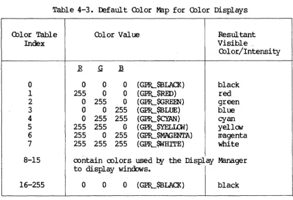
A-3 A-4 A-5 2-1 2-2 3-1 3-2 3-3 4-1 4-2 4-3 6-1
Defaul t Attr ibute settings • • • • • • • • • • • • • • • • • • • Example of Gray-Scale Color Values and Visible Intensities
2-2 2-3 3-10 3-11 3-12 4-2 4-3 4-4 6-3 Default Color Map for Monochromatic Displays • • • • • Defaul t Color Map for Color Displays •
Characteristics of Bit Block Transfers • • • •
CBAPrER 1
lNTROrucrION 'IO GRAFHIrn PRIMITIVES
This chapter briefly describes the uses and characteristics of the graphics priIl"itives routines (GPR). 'Ihe graphics prirr~tives library is built into your OOMAIN systat'. The routines (priIPitives) that roake up the library let you roanipulate the least divisible graphic elarents to develop high-st:eed graphics o~rations. 'Ihese elarents inclu<E lines and IX>lylines, text fonts and values, pixel values, and display ty~s.
'!he OOMAIN systat' also has an optional Core graphics package. The Core graphics };8ckage provides a high-level graphics environrrent in which to build IX>rtable graphics application systars. FOr a detailed description of Gore graphics, see the Programwer's Guide to Apollo Core Graphics.
1.1 USES OF GRAHiICS PRIMITNFS
The graphics pr~itives include the following capabilities: • Drawing lines, circles, and rectangles
• AOIuiring text fonts and roanipulating text • Manipulating graphics with bit block transfers • Filling IX>lygon areas
• AcooIrIrodating input o~rations
• Setting attributes
• Enabling direct graphics o~rations
• IrPaging with an extended color range • Storing bitwaps externally
The GPR J;ackage uses the follooing COIl'FOnents of the OOMAIN systerr.
• A display, l024x800, 800xl024, or l024xl024 visible pixels • Dispiay ~ory, l024xl024 pixels, or l024x2048 pixels • Any portion of progr~ Il'En'ory
• A set of graphics priIl'itive routines (all begin with "GPR") • Optionally, the Display Manager
1.2 rnARACI'ERISTICS OF GRAFHICS PRIMITIVES
Graphics priIl'itives are device dependent with res~ct to the display. H<Mever, they are independent of the various display enviroments. '!he
o~rating systeIY' provides two other sets of calls to JPanipulate the display: Display Manager interface -- These prograr calls (which begin with PAD)
all<M you to JPanipulate
rads
and frarres to display text. You cannot Il'anipulate graphics using these calls.Display driver interface -- '!he Display Manager nomally controls the OOMAlN display. All prograr rEquests to read or write the display are directed to the Display Manager, which in turn calls the display driver to ferfom screen operations for II'onochraratic displays. Most of the display driver (SMD) calls duplicate functions nCM provided
l:¥
the graphic pr~itives J;ackage.For a· descriIX:ion of the calls to the Display Manager interface and the dispiay driver interface see the OOMAIN &yst.eJr Programrer's Reference Manual.
GPR routines are independent of the display enviroments in two ways. First, you can rm a prograr which includes GER routines on any of the displays without JPodifying the prograr.
Second, graphics priIritives routines can issue calls to either the Display Manager or the display driver. 'Iherefore, if you use the graphics priIl'itives routines, you can easily change prograr execution frOIP one display !rode to another
l:¥
changing one option in the initialization routine GPIL$INIT.CBAPl'ER 2
DISPLAY ENVIRGIMENTS
This chapter describes the display configurations, fomats, and Irodes within which the graphics routines can o~rate.
2.1 DISPLAY OONFIGURATIONS
All OOMAIN displays are bi t-rrapped raster-scan devices. Each node bas one of three tyr;es of OOMAIN displays:
• color
• oonochraratic portrait (vertical)
• Ironochraratic landscar;e (horizontal)
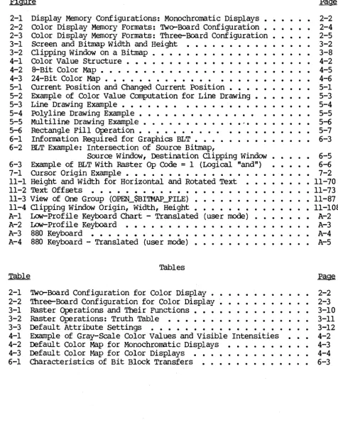
2.1.1 MonochroWatic Di~lRYs
Monochraratic displays are either black and white or black and green. '!be Ironochraratic display nerory is 1024 pixels wide and 1024 pixels high. '!here are two different oonochraratic display devices: :fX)rtrait and landscar;e. On the IrOnochraratic portrait display, the left-IrOst 800xl024 pixels are visible. On the IronochrCll'atic landsca~ display, the top 1024x800 pixels are visible. Figure 2-1 shows the II'onochrCll'atic display configurations.
1024 PIXELS
PORTRAIT DISPLAY
800 PIXELS
VISIBLE DISPLAY
224 PIXELS
_--- HIDDEN DISPLAY ___
LANDSCAPE DISPLAY
r--1024 PIXELS
VISIBLE
DISPLAY 800 PIXELS
224 PIXELS
Figure 2-1. Display Marory Configurations: Monochraratic Displays
2.1.2 Color DispJ~s
'!he oolor display has two types of forrrat: interactive and iIraging. The interactive forrrats support all GPR operations. 'nle iIraging fomats sUp!x>rt liIrited GPR operations, but provide the ability to display oore colors. In iJraging fomat, iIrages are displayed with Irore bi ts ~r pixel than they are in interactive forrrats. This is useful for 001 or correction in true-color iIraging.
2.1.3 Hardware Configurations for Qolor DisplAYS
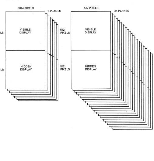
Color displays have either a two- or three-board hardNare configuration. For either oonfiguration, progrars can change the display between the two types of fomats. Both types of fomat are available with both har&are configurations, as shown in Tables 2-1 and 2-2. 'Ibis weans that either configuration provides both interactive processing and Irore extensive color display •
Table 2-1. FJWo-Board Configuration for Color Display
Fomat Pixel Di.Jrensions
Visible Display Hidden Display Nurber of Colors
4-bit interactive (Default) 1024 x 1024 1024 x 1024 16
8-bit iIraging 1024 x 1024 none 256
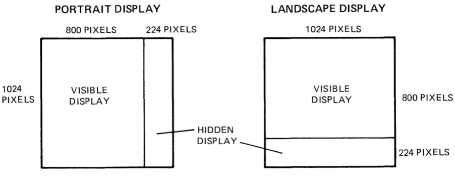
[image:21.613.80.531.87.263.2]Table 2-2. rrhree-Board Conf iguration for Color Display
FoI1Nlt Pixel Diroensions
Visible Display Hidden Display NlIl'ber of Colors
a-bit interactive (Default) 1024 x 1024 1024 x 1024 256
24-bit iIraging 512 x 512 512 x 512 16 Irillion
Two=Board Oonfiguration
The interactive 4-bit pixel forrrat is the default for a two-board configuration. This Ireans that 4 bits are used to assign a pixel value (color JraP index) to each pixel. '!his fomat allcws sixteen different oolors to ag;>ear on the screen at one tirre. '!he pixels are arranged 1024 x 1024 in visible display rrerory and 1024 x 1024 in hidden display.
Interactive fonrats supp:>rt all GPR o~rations.
Optionally, software can change a two-board configuration to an a-bit iIraging fonrat, with a bits used to assign a pixel value (color Il'ap index) to each pixel. This fOIll'at allcws 256 colors to appear on the screen at one tiIre, but requires only two boards. The pixels are arranged 1024 x 1024 in the visible display. '!here is no hidden display. III'aging fonrats st.g?Ort only liIrited GPR o~rations.
Three-Board Configuration
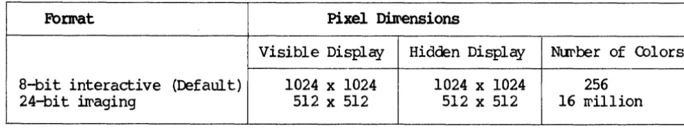
'!he interactive a-bit pixel fomat is the default for a three-board configuration. '!his rreans that a bits are used to assign a pixel value (color Il'ap index) to each pixel. This forrrat allcws 256 different colors to appear on the screen at one tirre. '!he pixels are arranged 1024 x 1024 in visible display rrerory, and 1024 x 1024 in hidden display. Interactive forrrats s1.1ptX>rt all GPR o~rations.
'!he a-bit interactive fOrIl'at is OOIl'p;ltible with the 4-bit interactive forrrat. For exarrple, the Display Manager uses 4-bit planes, but rms on a oonfiguration using 8-bit planes. In general, the o~rations ~rfoIll'ed in an 4-bit fOIll'at can be ~rfomed in a-bit fonrat.
Optionally, software can change a three-board configuration to a 24-bit iIraging forrrat. 'Ibis Il'eans that 24 bits are used to assign a pixel value (color Il'ap index) to each pixel, Iraking it {X)ssible to use 16 Iril1ion different colors. '!he pixels are arranged with 512 x 512 in visible display and 512 x 512 in hidden display. IIraging fomats sup};Ort only liIrited GPR o~rations.
Figure 2-2 and Figure 2-3 show the oolor display fomats available for two-board and three-board harc1vare conf igurations.
[image:22.617.76.574.127.220.2]1024 PIXELS
1024 PIXELS
INTERACTIVE 4·BIT PIXEL FORMAT
1024 PIXELS
VISIBLE DISPLAY
HIDDEN DISPLAY
I I
I
~
l-~
I-4 PLANES
I-1024 PIXELS
I
IMAGING 8·BIT PIXEL FORMAT
1024 PIXELS
L
VISIBLE DISPLAY
I
I
NO HIDDEN DISPLAY
l
-8 PLANES
I---
--
I
-Figure 2-2. Color Display Merrory Fonrats: 'lWo-Board Configuration
[image:23.618.50.574.62.697.2]LS
,LS
INTERACTIVE a·BIT PIXEL FORMAT
1024 PIXELS VISIBLE DISPLAY HIDDEN DISPLAY I I I I 8 PLANES
-I---
----
-512 PIXELS 512 PIXELS T T
IMAGING 24·BIT PIXEL FORMAT
512 PIXELS
24 PLANES
---
--
-VISIBLE DISPLAY
---
~-
---
I-i--
~I-HIDDEN
I-DISPLAY l-
I- l-
I
--
-
i
-I I --. I 1 I I T I L I I I I I I I I IFigure 2-3. Color Display Merrory Fbmats: Three-Board Configuration
[image:24.612.48.554.178.708.2]2.2 DISPLAY MODES
A graphics prograIr can run in one of four lI'odes:
• BorrCM-display 1I'Ode: on the full screen, which is tarp:>rarily borrowed frar the Display Manager. '.Ibis lI'ode has the option not to clear the screen.
• Direct Mode: within a window, which is acqui red frar the Display Manager for a r;eriod of tilI'e.
• FraIre ~de: within a frarre of a Display Manager p:ld.
• No-Display Mode: without a display, using only bitIraps allocated in lI'ain lI'EfI'ory.
Progr~s select a display II'Ode when th~ initiate a graphics session (with
GPIL$INIT) • ltbst of the graphics routines can o~rate within any of these rrodes; sare routines 00 not o~rate in fraIl'e lI'ode. III'aging fomats rEquire borrow-display lI'ode.
2.2.1 Borrow-DisplAY Mode
In borrow-display rrode, the prograr borrows the full screen and the keyboard frat' the Display Manager and uses the display driver directly through GPR software. All Display Manager winoows disappear frar the screen. llie Display Manager oontinues to roo during this tilI'e. However, it ooes not write the output of any other processes to the screen or read any keytoard input until the borrowing progr~ returns the display. Input typed ahead into input pads way be read while the display is borrowed. BorrCM-display Irode is useful for prograrrs that rEquire exclusive use of the entire screen.
An option in borrCM-display rrode allows you to allocate a bi map in display Irel'ory without setting all the pixels to zero. '.Ibis is useful for copying what is on the screen into a file to save for later display or printing.
2.2.2 Direct Mode
Direct wode is silI'ilar to oorrow-display lI'ode, but the prograr borrows a window frat' the Display Manager instead of borrowing the entire display. '!he Display Manager relin:xuishes oontrol of the window in which the prograrr is executing, but oontinues to run, writing output and processing keyboard input for other windows on the screen. Direct II'Ode offers a graphics application the r;erfomance and unrestricted use of display car:abilities found in borrow-display rrode and, in addition, r;emits the application to ooexist with other activities on the screen. Direct wode should be the preferred lI'ode for wast interactive graphics applications.
Chapter 8 describes how prograws perfo~ graphics input and output in
di rect rrode.
2.2.3
Frawe
ModeAlternately, a graphics prograw that executes within a fraIPe of a Display Manager {Bd calls the Display Manager, which interacts with the display driver. A graphics prograrr executes rrore slCMly in frarre rrode than in borrCM-display Il'odei however, fraIPe rrode offers sare additional Display Manager features:
• A fraIl'e provides a nvirtual displayn that can be larger than the window, allowing the user to scroll the window over the fraIl'e.
• Frarre rrode Il'akes it easier to perfo~ ordinary streaIr I/O to input and tr anscr ipt {Bds
• In frarpe Il'ode, the Display Manager will reproduoo the mage when neoossary.
• The prograr can leave the iIl'age in the p:td upon exit so that users can viey it at SOIl'e later tirre.
Frarre Irode currently places sare restrictions on the GPR o~rations that are allCMed. Chapter 11 describes the individual routines, including their
restrictions. One restriction is described belCM.
~eFentation Restrictions
on
Color/Intensity Values in Frame ModeCurrently, the Display Manager roes not store a bi map when a prograrr operates in frarpe Il'ode. 'Iherefore, a prograr using frarre rrode cannot call graphics routines which depend on particular pixel values of the current bitIrap. '!hese routines include pixel read and write o~rations, BLTs that use source data frar the fraIl'e, and GPIL$lNLBITMAP_OOINTER.
2.2.4 No-Dispi~ Mode
When the prograrr selects no-display at initialization, the GPR initialization routine allocates a bitIrap frar rein Il'at'ory. '!he prograrr can then use GPR routines to ~rforrr graphic o~rations to the bitll'ap, i¥passing any screen display entirely. Applications can use no-display
Ir<X.E to create a Il'ain Il'E!l'ory bitll'ap, then call graphics rrap file routines to Il'ake a file, or send the bitll'ap to a periIileral device, such as a printer.
2.3 USThG CDLOR DISPLAY FORMATS
Interactive display fomats fully sUPIX>rt all GPR output o~rations --block transfer, area filling, line drawing, text Iranipulation. I:Iraging display fomats support only liIrited display o~rations -- displaying (not reading) pixel data and changing the color II'ap (see <l1apter 4 for a discussion of color II'aps). Other functions will return error Iressages. I:Iraging display fomats II'ake it I:X>ssible to display iIrages with Irore bits
~r pixel than are available with interactive fomats. Additionally, in 24-bit pixel fomat, select frarre o~rations (GP}L$SELEcr_CDLOR_FRAME) are allCMed. '!hese op:rations are used to look at either half of display II'E!'(Iory.
2.3.1 Using Imaging DiRPl~ Forwats
Svitching the display between an interactive fomat and an irraging fomat causes the harcware to reconfigure the refresh buffer WE!l'ory and to rearrange the bi map. 'Ibis II'eans that an intelligible mage in one fomat becoIl'es unintelligible in another.
The imaging fomats are supported only in borrCM-disp].ay rrode. TO change frat' an interactive to an iwaging fomat, you Il'ust be in borrow-display Irode.
2.3.2 Routines for !waging DiRPlqy FOrmats
Use the follCMing routines and procedures for irraging display fomats. Fbr a detailed description of these calls, see Chapter 11 of this Il'anual.
1. Establ ish bor reM-displ ay IrOde: GP1L$INIT
You way or IPay not first want to ~rforIl' sare graphics o~rations in interactive fomat.
2. Set the display to 24-bi t pixel fomat:
GPR_$SET_I~ING_roRMAT
Use the fomat ar~ent to switch to 8- bit or 24-bit iIl'aging fomat.
3. To in:Jui re about the fomat, use :
4. 'lb establish new values for the color wap, use:
5. 'lb write pixel data to the display, use:
6. 'lb return to interactive fomat, use the follCMing call with the interactive ar~ent:
7. 'lb teminate the session and return the display to the Display Manager, use:
CBAPI'ER 3
MEIDRY REPRESENTATION: BITMAPS AND PIXELS
This chapter describes bi trrap structure and pixels in relation to graphic storage and representation. '!he chapter includes discussion of bitrraps in display and Il'ain ll'€Il'ory, bitIrap routines, and bitIrap attributes.
A hitwap is a rectangular data structure that stores a graphic iIl'age. A pixel (picture el~ent) is a discrete point of a graphic iIl'age. Each pixel in a display has a oorresponding address in a buffer which stores the mage. '!hus, pixels provide the rreans of displaying a graphic iIrage. '!his section describes bitIrap structure and pixels.
3.1 BITMAP S'IRUcruRE
On a bit-napped display, a one-to-one cor respondence exists between the
screen iIl'age and display IrEII'ory. On the screen, a rectangular array (a raster) of pixels foms the visible iIrage. In warory, a bi tIrap, a rectangular data structure, stores the graphic iwage.
A bitIrap is a three-dirrensional array of bits, having width, height, and
depth. On the Il'onochraratic display, bi tIrap width and height way vary; the
depth €quals one. On the oolor display, bitIrap width, height, and depth can vary.
BitIrap width and height oorrespond to iw.age width and height. BitIrap width is represented
l:¥
x-coorclinates ranging frar zero on the left to a xraxiIrtll' defined for the bitIrap on the right. BitIrap height is representedl:¥
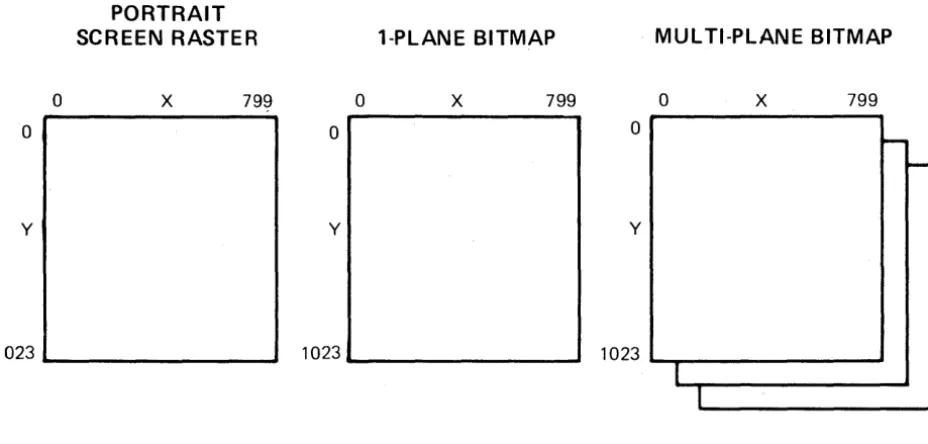
y-coordinates ranging frat" 0 on the top to a rraxiwllT' defined for the bitrrap on the bettar (see Figure 3-1). When a prograrr establishes bitIrap size, it detemines the rraxill'tJr x- and y-coorclinates. For bitIrap size Imitations, see GPIL$INIT.BitIrap depth specifies the nuwber of bits of infor.wation associated with each pixel. Each one-bit-deep slice of a bitrrap is called a plane of the bitrrap. This slice has the scure width and height as the bit:IPap.
On the wonochraratic display, bitrraps oontain one plane; the depth of displayed bitrraps is one bit. On the color display in 4-bit pixel rode, bitIraps can oontain up to 4 planes; displayed bitrraps can be up to 4 bits
deep. On the oolor display in 8-bit pixel Irode, bimaps can oontain up to 8 planes; displayed bitlI'aps can be up to 8 bits deep.
Planes are nurbered frm zero to the nurber of bit planes in the bit:rrap winus one. Plane zero holds the least significant bits of the pixels, and the highest nurbered bit plane holds the wost significant bits.
o
o
y
PORTRAIT SCREEN RASTER
x
7991023 _ _ _ _ _ _ _ __
1-PlANE BITMAP
o
x
799o
y
1023 _ _ _ _ _ _ _ _
MULTI-PLANE BITMAP
o
x
799o
-y
1 023 ""'-~---'
I
I
Figure 3-1. Screen and Bimap Width and Height
3.2 PIXELS
-On the 1l'onochraratic display, each pixel oonsists of one bit. On the rolor display, a bimap can have rrultiple planes. 'Iherefore pixels on a color display can oonsist of a group of bits.
The bitIl'ap pixel values are used ~ the color 1l'ap to generate the visible intensity (dark or bright) or rolor of the rorres];Onding screen pixel.
X-and y-coordinates reference pixel ];Ositions on a bimapped (raster) display and in a bi map.
The distance between adjacent pixels on a raster display is called a raster unit. '!he ooordinate p:>sition (0,0) is at the top left mrner of the screen, the Display Manager frarre, or the bimap. 'lb change the ];Osition of the origin, use GPIL$<DORDINATE_ORIGm.
[image:31.618.69.533.191.413.2]3.3 BITMAPS IN DISPLAY, MAlN MEIDRY, AND IDcr'ERNAL SIORl(;E
A bitrrap way reside in display Iral'ory, wain warory, or external storage. A
single graphics session (beginning with GPR-$INIT and ending with
GPR_$'rERMINATE) can involve zero, one, or wore bitrraps in display Irarory and wultiple bitrraps in wain warory. A bitrrap resides in only one location at any tiwe.
A bitrrap in display Iral'ory is visible on the screen. A bitrrap in II'ain lI'at'ory rrust
re
oopied to display rrarory to beCOfPe visible. A bitrrap file way beo~ned to create a bitrrap and store it on the disk. '!he bitrrap on which a prograr is o~rating, whether it resides in display or wain lI'at'ory, is called the current bitmap. '!he first bitrrap created in a graphics session is called the initial bitIrap.
3.3.1 Bitlraps in Display MarotY
Most progrars that include a bitIl'ap in display rrarory can execute in borrow-display IrOde, direct Irode, or frarre wode. When a prograr initializes the graphics prirritives, it way select any of theselI'odes. Progrars that use the iIraging fomat for oolor display !rust be initialized in borrav-display
IOOde. These display rrodes ~rtain only to progrars which use the screen for display of mages. For bitrraps of progrars that cb not display an iIrage, see the section below.
On a wonochraratic display, bitIl'aps in display lI'arory can oontain only one plane. '!he initial Jre.XiwtJr' bitrrap size is the size of the visible wonochraratic display, 800xl024 pixels for I=Ortrait displays, and l024x800
for landsca~ displays.
For a color display in a 4-bit interactive fomat, display rre:rory bitrraps can oontain up to four planes; in 8-bit interactive or iIraging fomats, they can oontain up to eight planes. In 24-bi t ireging fomat, they can oontain
up to 24 planes. '!he initial rraxiIrL1I' bitrrap size is the size of the visible 001 or display: l024xl024 pixels for 4-bit and 8-bit fonratsj 512 x 512 for a 24-bi t fomat.
3.3.2 BitIraps in Main MerrotY
If a prograr selects not to display an iIPage on the screen, it can rranipulate the iIrage
l¥
allocating a bitrrap in wain warory. A prograr lI'ight rafuire lI'ain lI'at'ory bi trraps, for exaxrple, to o:Ferate on a bi trrap larger than thatavailable in display Irarory.
Main warory bi maps can contain up to eight planes, arranged 4096x4096 pixels, regardless of the display in use. However, if a wain lY'at'ory bitrrap is transferred to display rrerory, the size of the bibl'ap transferred is restricted according to the display ty~.
3.3.3 Bitwaps in External storage
'!he routine GPIL$OPEN_BITMAP_FILE allCMS you to create or o};en a file for storage of a bi~ap on the disk. This ~eans that you can define a graphic iIrage on a bi~ap, store the bi~ap in a file, and then access it for· display at a later ~e. You; can treat bi trl'aps for external storage like any other GPR bi~ap.
3.3.4 Initial Bitmap
When a prograrr calls GPR_$INIT to initialize the graphics p:lckage, it selects a lI'ode of o};eration and initial bi~ap size. An initial bitrl'ap is created as follows:
• If the prograr uses the display and o};erates in frarre ~ode, the initial (and current) bitrl'ap is displayed and is the saIl'e size and location as the fraJrle. '!he graphics prmitives create the frarre with the size pararreters which the prograw s};ecifies.
• If the prograr ot:erates in direct or borrCM-display wode, the initial (and current) bi~ap is also displayed. '!be prograrr chooses the bi~ap size, which can be Equal to or less than the size of the screen. If the bitrl'ap is sraller than the screen, it is located in the top left-rost area of the screen or window. '!be (0,0) bi~ap·
coordinate is in the saIl'e I;X)sition as the (0,0) screen coordinate.
• If the prograrr <:bes not use the display, the graphics priIritives initialization routine designates an initial bitrrap in rrain rrEIrory. This bi~ap has the dirrensions which the prograrr has selected. In
this case the initial, current bitrl'~p is not displayed.
3.4 RClJTlNES FOR rnEAT]R;, C'ANCELlm, IDENTIFYIK; BITMAPS
The following routines include features for creatin9' deleting, and identifying bi ~aps:
• GPIL$INIT -- initializes the graphics p:tckage and establishes a current bi~ap either in display trarory or wain Irarory, as s};ecified
l:¥
the prograrr.• GPIL~ERMINATE -- teminates the graphics p:tckage and its bi~aps.
• GP.EL$ALI.DCA~BITMAP -- allocates a bitrl'ap in rrain ~arory and returns
a mique descriptor for the bitIrap.
• GPIL$DEALIDC'ATE-BITMAP -- deallocates an allocated bi~ap.
• GPlL$ALIDCATE_BITMAP_NC -- allocates a bitIl'ap in II'ain II'aI'ory without setting all the pixels in the bit:rrap to zero, and returns a unique descr i ptor for the bi map.
• GP1L$AI..IDCATE_HIlLBITMAP -- allocates a bi map in hidden display rrarory.
• GP1L$SET_BITMAP -- establishes a specified bit:rrap, in displ~ nEroory or wain II'aI'ory, as the current bit:rrap.
• GP1L$SET_W]NDOW_ID -- establishes the character that identifies the current bitIrap's window.
• GPR-$~WINDOW_ID -- returns the character that identifies the current bit:rrap's window.
• GPlL$~BITMAP -- returns the unique descriptor for the current
bi t:rrap, which is in either display rrarory or wain II'aI'ory.
• GPIL$~BITMAP_DIMENSIONS -- returns the size and ntIl'ber of planes
of a bitFap.
• GPIL$SET_BITMAP_DIMENSIONS -- changes the size of a previously crea ted bi tIrap.
• GPR_$~B!LBIT_OFFSET -- returns the offset of the left edge of the bibl'ap in virtual address Stace.
• GPR-$OPEN_BITMAP_FILE -- Of:ens a file for external storage of a bibl'ap.
3.5 ACCESSThG AND MANIroLATING BITS IN A BITMAP
As descrited above, a bitrrap is a data structure. When a prograr allocates a bi tIrap, the graphics p:ickage II'aps this data structure into the virtual address sp:tce. '!he prograr has no oontrol of the location or layout of a bitIrap in virtual address sp:tce. 'lYPically, the bits oonstituting one bibl'ap
scan line (one horizontal line in a single plane) occupy sequential locations in the address sp:tce. Next, a series of address locations is skip~d. '!hen, all the bits of the second scan line are stored, and so on. For a given bitIrap, the offset in II'aI'ory frat' the teginning of one scan line to the next rarains constant.
For II'ul tiple-plane bitIl'aps in Fain II'at'ory, plane 1 starts on the scan line iIm"ediately follCMing the last scan line of plane O. For bit:rraps stored in bitIrap files, this is not necessarily true. '!he routine GPR_$OPEN_BITMAP_FILE returns the offset in II'arory between planes. Unlike II'ain warory bitIraps, displayed wultiple-plane bibl'aps on the color display can te accessed only one plane at a tiIre. Prograrrs II'ust call the routine GP1L$REW\P_<DLOR_MEK>RY to select the plane to access.
To access a bit location in order to clear or set the bit value, a prograr does not speci~ bi~ap x- and y-coordinates. The progr~ ~ust find the location of the bit in the virtual address Sp:lce to ~anipulate it. 'Ib find bit locations, progrars can use the routine GPR_$nQ..BITMAP_OOINTER. This routine returns a pointer to the beginning address of the bitwap's storage,
as well as the nll1'ber of l6-bit words (the offset) between the beginning of storage for eaCh successive scan line.
If a prograr uses the pointer routine to get the address of display ~arory
(oooochraratic and color) , it should call the routine GPlL$ENABLE_DIRECl'_ACCESS after any calls that change the display and before using the pointer returned
t¥
GPfL$nQ..BITMAP_OOINTER. This ensures that any~nding display haravare o~rations are COIl'plete before the prograrr uses the p:>inter to access display xrerory (with the routines GPfL$READ_PIXELS and GPlL$-lRITE_PIXELS) •
For exaxrple, to set a bit to I at the bi~ap coordinate position x
=
64,Y = 3, you can wri te a section of a EOR'lRAN progr a.r, using the pointer statarent, as follavs:
C
C
C
INTmER*2 X, Y INTEGER*2 BIT_WORD . INTEGER*4 INDEX
INTmER*4 BITMAP_PI'R, BITMAP_DESCRIPrOR, STA'IUS INTmER*2 OFFSET
INTmER*2 BITMAP
OOINTER /BITMAP_~ BITMAP(O:65535)
CALL GHL$ENABLE_DIRECI'_ACCESS (Sl'AW S)
CALL GPfL$nQ..BITMAP_OOINTER (BITMAP_DEScru:PlOR, BITMAP_Pm,
I OFFSErr', STAWS)
C To set bit at (x = 64, Y
=
3) to 1:C
X = 64 Y=3
INDEX
= (Y
*
OFFSET) + (X / 16) BIT_WORD = RSHFr(16#8000, IDD(X, 16»BITMAP (INDEX)
=
OR (BITMAP (INDEX) , BIT_WORD)3.6 MULTII:LE DISPLAYED BITMAPS
To initialize II'ore than one window with graphics priII'itives, you can use GPlL$INIT II'ore than once. 'lb cb so, you II'ust s};ecify frarre or direct display rode in the unit pararreter. '!he streaII' identifier for the pad II'ust be
different for each window.
You can draw in all the windows, one at a tiII'e, by calling GPlL$SEr_BITMAP as for other drawing o};erations. '!he bi~ap descriptor is returned autaratically for each initialized window.
calls which access the display bi~ap go to the wost recently current screen bitrrap. 'Ibis II'ay be the current screen bitrrap or the screen bitrrap that was rrost recently current if the current bitrPap is a warory bitrPap.
With rrultiple displays, input events can COIl'e frar several different bitrraps.
To identify the source of an input event, the routine GPR-$E.VENI'_WAIT or GPlL$CDND_EVENT_WAIT returns a character. 'Ibis character is established with the routine GPIL$SET_WINIXlV_ID, associated with an entered winoow event. That character tells you which window you have just entered. '!he source of input rarains the saIre until a left window event is received.
To establish the identifying character for a window, use the routine GPlL$SET_WINIXlV_ID. '!his routine accepts a character which identifies the current screen bi~ap or the Il'ost recent screen bitrrap. If the current bitrPap is the screen bitrPap, it references that one. If the current bitrrap is in warory, the routine uses the wost recently current bitrrap.
Use GPlL$SET_WINDOW_ID to associate a different character with each window. A prograrr II'ust enable entered winCbw events for all windows that will have such events.
3. 7 BITMAP A'nRffiUTES
Each bi trPap bas a set of attr ibutes which sIEcify the II'anner in which subsequent oJ;erations on the bi trrap will be ~rfomed. For excurple, attributes can s~cify that only a certain section of the bit:rrap can be
II'anipulated in any subsequent ot:erations or that text written on the bi t:rrap will be displayed in sIEcified fonts.
3.7.1 Description of Attributes
For each bitIrap, the prograrr Irust allocate an attribute block and then assign it to the bit:rrap. '1he attributes in the block sJ;ecify characteristics of graphics oJ;erations.
Bit:Irap attributes are the follCMing: clipping wincbw, ooordinate origin, draw value (pixel value), fill value (pixel value), text value, text tackground value, text font, line style, plane rrask, and raster o~ration. 'Ihese attributes are described belCM.
Clipping Window
The clipping window attribute s~cifies a rectangular seCtion of the bit:Irap, outside which no pixels can be rrodified, as suggested in Figure 3-2. (GPR....$SE'I'_a..IPPI~_AcrlVE (bes not draw a rectangle, but s};:ecifies a rectangular area.) After a prograr calls the routine GPlL$Sm....<LIP_WINIXlV to s:t:ecify the clipping window, it rray call GPlL$SRr_<LIPPING_AcrlVE to enable the clipping window.
BITMAP
CLIPPING - _ _
WINDOW
Figure 3-2. Clipping Wincbw on a BitIrap
Coordinate Origin
'!he coordinate origin s~cifies a {air of offset values to add to all coordinate };X>sitions. '!hese values are subsequently used as input to wove,
line drawing, or bit block transfer (BLT) o~rations on the current bitrrap. For exaJrple, the coordinate origin affects calls to the routines GPIL$KJVE, GPlL$LINE, and GPIL$PlXEk..BLT.
praw Value
'!he draw pixel value s~cifies the value to which pixels will be set when
dr awing 1 ines. Fill Value
'!he fill pixel value s~cifies the value to which pixels will be set when filling areas.
Text Value
'!he text pixel value ~cifies the value to which pixels will be set to write text.
Text Background Value
'!be text backgrolIDd pixel s~cifies the value to which pixels will be set for text backgromd.
Text Foot
'!he text font attribute s~cifies the font in which to display text characters in the bitrrap.
Line style
'!he line style attribute s~cifies the style in which to display line se<}l'ents in the bi map. Line sty Ie can be either sol id or dashed; if dashed,
the style scale factor ~temines the length of the dash.
Plane Mask
'!he plane Il'ask sp:cifies which planes of a bitrrap canre wodified ~ any
graphics op:ration and which planes are protected fr~ wodification. Raster Operation
A raster o~ration s};ecifies the wanner in which to oorrbine pixels in one plane of source and destination bimaps to fom a new destination bimap. The value of each new destination bit is assigned ~ a Boolean function of the previous value of each destination bit and the value of the oorres};X>nding source bit.
Sixteen raster operations fonm the set of rules for combining bit values. Assigning a raster operation code to a plane of a bitmap alters no values.
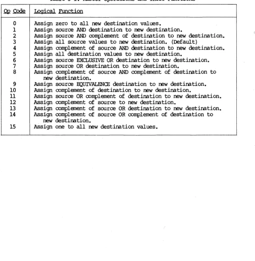
The raster operation code controls how values are logically combined when a program subsequently draws or uses a bit block transfer (BLT) to combine two bitmaps. (See Chapter 6 for a description of BLTs and their use of raster operations. ) Table 3-1 lists the op codes and logical functions for the sixteen raster operations. Table 3-2 is a truth table of the raster operations.
Table 3-1. Raster Operations and Their Functions
.0!2
Code Logical Functiono
Assign zero to all new destination values.1 Assign source AND destination to new destination.
2 Assign source AND complement of destination to new destination. 3 Assign all source values to new destination. (Default)
4 Assign complement of source AND destination to new destination. 5 Assign all destination values to new destination.
6 Assign source EXCLUSIVE OR destination to new destination. 7 Assign source OR destination to new destination.
S Assign complement of source AND complement of destination to new destination.
9 Assign source EQUIVALENCE destination to new destination. 10 Assign complement of destination to new destination.
11 Assign source OR complement of destination to new destination. 12 Assign complement of source to new destination.
13 Assign complement of source OR destination to new destination. 14 Assign complement of source OR complement of destination to
new destination.
15 Assign one to all new destination values.
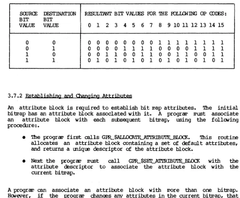
[image:39.613.60.565.217.734.2]Table 3-2. Paster Of;erations: Truth Table
SaJR<E DESTINATION . RESULTANT BIT VALUES FOR mE FOLI.&]N; OP <DIES: BIT BIT
VALUE VALUE 0 1 2 3 4 5 6 7 8 9 10 11 12 13 14 15
0 0 0 0 0 0 0 0 0 0 1 1 1 1 1 1 1 1
0 1 0 0 0 0 1 1 1 1 0 0 0 0 1 1 1 1 1 0 0 0 1 1 0 0 1 1 0 0 1 1 0 0 1 1 1 1 0 1 0 1 0 1 0 1 0 1 0 1 0 1 0 1
3.7.2 Establishing and Changing Attributes
An attribute block is ra:;Iuired to establish bit II'ap attributes. '1he initial
bi~ap has an attribute block assocIated with it. A prograw II'ust associate an attribute block with each subsequent bitrrap, using the follGling procedure:.
• rrhe prograr first calls GPR_$ALIDCATE_ATrRIBUTE_BIDCK. 'Ibis routine allocates an attribute block containing a set of default attributes, and returns a unique descriptor of the attribute block.
• Next theprograr II'ust call GPR_$SET_ATrRIDUTE_BIDCK with the attribute descriptor to associate the attribute block with the current bitIrap.
A progr~ can associate an attribute block with II'Ore than one bitIrap. Ha.lever, if the progran: changes any attributes in the current bitrrap, that attribute will be changed on all other bitrraps which have the saxre attribute block as the current bitrrap.
[image:40.615.61.551.116.521.2]