Abstract--In order to achieve the optimal design based on some specific criteria by applying conventional techniques, sequence of design, selected location of PSSs are critical involved factors. This paper presents a method to simultaneously tune PSSs in multimachine power system using hierarchical genetic algorithm (HGA) and parallel micro genetic algorithm (parallel micro-GA) based on multiobjective function comprising the damping ratio, damping factor and number of PSSs. First, the problem of selecting proper PSS parameters is converted to a simple multiobjective optimization problem. Then, the problem will be solved by a parallel micro GA based on HGA. The stabilizers are tuned to simultaneously shift the lightly damped and undamped oscillation modes to a specific stable zone in the s-plane and to self identify the appropriate choice of PSS locations by using eigenvalue-based multiobjective function. Many scenarios with different operating conditions have been included in the process of simultaneous tuning so as to guarantee the robustness and their performance. A 68-bus and 16-generator power system has been employed to validate the effectiveness of the proposed tuning method.
Index Terms—Hierarchical genetic algorithm, multiobjective
design, parallel micro genetic algorithm, power system stabilizer tuning.
I. INTRODUCTION
ITH the increasing electric power demand and need to operate power systems in a faster and more flexible manner in the deregulated competitive environment,
K. Hongesombut is with the Department of Electrical Engineering, Kyushu Institute of Technology, Kitakyushu, Fukuoka 804-8550, JAPAN (e-mail: [email protected]).
Y. Mitani is with the Department of Electrical Engineering, Kyushu Institute of Technology, Kitakyushu, Fukuoka 804-8550, JAPAN (e-mail: [email protected]).
S. Dechanupaprittha is with the Electrical Power Engineering Program, Sirindorn International Institute of Technology, Thammasat University, Patumthani 12121, THAILAND (e-mail: [email protected]).
I. Ngamroo is with the Electrical Power Engineering Program, Sirindorn International Institute of Technology, Thammasat University, Patumthani 12121, THAILAND (e-mail: [email protected]).
K. Pasupa is with the Electrical Power Engineering Program, Sirindorn International Institute of Technology, Thammasat University, Patumthani 12121, THAILAND (e-mail: [email protected]).
J. Tippayachai is with the Electrical Power Engineering Program, Sirindorn International Institute of Technology, Thammasat University, Patumthani 12121, THAILAND (e-mail: [email protected].)
recent power systems can reach stressed conditions more easily than the past. These cause unstable or poorly damped oscillations that have been observed more often in today’s power systems. Therefore, serious consideration is now being given on the issue of increasing power system stabilization performance. Applying power system stabilizers (PSSs) can enhance dynamical oscillations by adding modulation signal through excitation control system of generator. Over the decades, PSS has been used by utilities in real power systems as it has been shown to be the most cost effective electromechanical damping control [1, 2]. Recently, many modern control techniques can be used to design different power system stabilizer structures. However, utilities prefer to choose lead-lad structure due to its simple structure and reliability in applying with real power systems. To increase the damping performance of stabilizers, researches have paid attention to tune these stabilizers simultaneously.
Several literatures have proposed approaches using genetic algorithm (GA) to robustly tune PSSs in multimachine power systems. The advantage of GA over other techniques is that it is independent of the complexity of problems; therefore, it is easy to apply for solving difficult problems. In PSS tuning, sequence of tuning and selection of location are critical involved factors in order to achieve optimal stabilization performance. PSS can be tuned to improve damping at one mode, but it may produce adverse effects in other modes. In addition, different placement of PSS makes the oscillation behaviors quite different at different operating conditions. Many researches using GA techniques in tuning PSSs can avoid sequence problem. However, they have to determine the locations of PSSs before staring the tuning approach. By this way, participation factor to identify the possible location has been extensively used in past researches [3-5]. Since the location has been fixed, optimal damping performance can only be guaranteed with this fixed structure. In general, having too many PSSs with improper setting may produce severely adverse effects to the other modes. Since these behaviors change in a rather complex manner, a set of PSS may no longer yield satisfactory results when the place is not chosen appropriately. As a result, it is necessary to minimize these adverse effects by using only necessary number of PSSs. This paper presents a method to simultaneously tune PSSs in multimachine power system using hierarchical genetic algorithm (HGA) and parallel micro genetic algorithm
Power System Stabilizer Tuning Based on
Multiobjective Design Using Hierarchical and
Parallel Micro Genetic Algorithm
K. Hongesombut, Member, IEEE, Y. Mitani, Member, IEEE, S. Dechanupaprittha, Non-Member,
I. Ngamroo, Non-Member, IEEE,K. Pasupa, Non-Member, and J. Tippayachai, Non-Member
the lightly damped and undamped oscillation modes to a stable zone in the s-plane. Multiobjective function comprising damping ratio, damping factor and number of PSSs is used in the proposed tuning method. Consequently the use of multiobjective function will therefore guarantee damping ratio, damping factor and possible PSS locations.
The proposed tuning method is applied to a 68-bus and 16-generator power system which is large and close to realistic power system. Several scenarios with different operating conditions have been included into the process of simultaneous tuning so as to guarantee the robustness and their performance of resulting PSSs. The results of close-loop eigenvalues and time domain simulations have been carried out to validate the effectiveness of the proposed method. The results demonstrate that and excellent improvement of dynamical oscillations for every scenario has been achieved with one set of PSS parameters.
II. STUDIED POWER SYSTEM MODEL
The power system considered in this paper is shown in Fig. 1. The power system comprises 5 coherent groups representing a reduced order of the New England and New York interconnected system. The thick lines indicate the major weak tie lines that cause the low frequency inter-area oscillations. Without PSS, this system is very unstable. There are number of aspects of power system stabilizer interaction which becomes apparent in this model. Details of network parameters, machines, excitation and governor systems, load flow are given in [8].
G6 G7 G4 G5 G3 G2 G9 61
29 22 58 23
[image:2.612.340.535.329.545.2]59 56 20 57 19 16 21 27 17 24 18 3 4 12 14 15 13 10 55 54 11 6 5 7 8 65 G13 37 64 G12 39 44 45 G16 68 52 50 51 35 34 36 9 30 1 G8 G1 26 28 25 60 53 2 32 63 33 G15 67 42 49 46 38 62 31 G11 47 48 40 66 41 G14 G10 Group1 Group2 Group3 Group4 Group5
Fig. 1. A 68-bus and 16-generator power system model
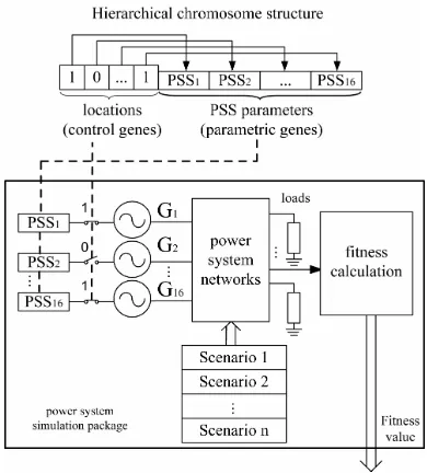
multilevel of genes as demonstrated in Figure 2 showing the HGA chromosome representation with one-level control genes and parametric genes. With this configuration, the control genes are analogous to the PSS locations. The control gene signified as “0” in the corresponding site, is not being activated meaning that the PSS at the corresponding location will not be installed into the power system during the simulation. Parametric genes are analogous to the PSS parameters to be optimized. Using the HGA concept, locations and PSS parameters can be simultaneously tuned. Fig. 2 illustrates the interface system of HGA chromosome structure and simulation package for calculating the fitness value. In many cases, other scenarios may be added arbitrarily by users depending on the critical events in power system operation. By HGA, it provides more flexibility and assures us that the optimal solution will always exist without biasing from the initial location determination.
Fig. 2. Hierarchical chromosome structure and system interface
B. Micro genetic algorithm and parallelization
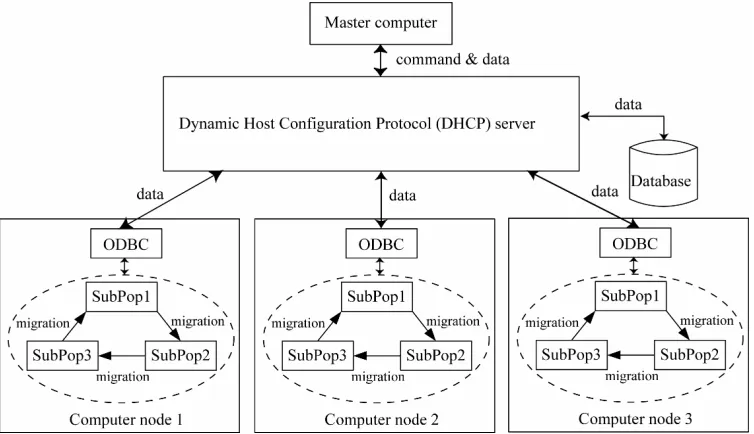
[image:2.612.63.287.479.699.2]In this paper, a micro-GA presented in [7] is used. Additionally, multipopulation evolutionary concept and parallel micro-GA are new features to implement on this work. A single population micro-GA performs well on a wide variety of problems. However, better results can be obtained by introducing multiple subpopulations. The multipopulation micro-GA models the evolution of a species in a similar way to nature. Fig. 3 shows the implementation of multipopulation micro-GA and parallelization. The parallel micro-GA is implemented through a Dynamic Host Configuration Protocol (DHCP) server. For each computer node, it is divided into multiple subpopulations, three for this experiment. These subpopulations evolve independently of each other for a certain number of generations. After that, the migration process is achieved by distributing a best individual between the subpopulation. The scheme of migration provides genetic diversity occurring in the subpopulation by exchanging of information between subpopulation.
The procedure of the parallel micro-GA can be described as follows:
Step 1: Master computer initializes the system counter to zero. Step 2: Each computer node initializes the generation counter to zero.
Step 3: Each computer node loads the best individual from the database and keeps the loaded solution in the subpopulation 1, then initializes the rest population.
Step 4: Each subpopulation for each computer node performs micro-GA by executing 5 operation steps as follows;
Step 4.1: Evaluate the fitness of each individual. Step 4.2: Perform the tournament selection. Step 4.3: Perform the discrete recombination. Step 4.4: Perform elitism mechanism.
Step 4.5: Check convergence. If converged by the constraint that the best fitness is different from average fitnessby 5% or less, then reinitialize the subpopulation by keeping the recent best individual and send it to the database through DHCP server.
Step 5: Each computer node performs the best individual migration between each subpopulation.
Step 6: Increase generation counter by one and each computer node checks whether the generation counter exceeds the maximum generation. If not, return to step 4.
Step 7: Check the system counter whether it exceeds the maximum value. If not, increase system counter by one and return to step 2.
The database is required to store and manage a number of scenario table and obtaining solutions. A prototype database system has been implemented in Microsoft Access 2000 in Windows XP professional operative system. Microsoft Open Database Connectivity (ODBC) driver which is a standard PC interface is used to enable communication between database management systems and SQL-based applications. Master computer can be used to collect results from the database, to update scenario table and to insert test solution into the database without interrupting the operation of each computer node.
IV. FORMULATION OF PROBLEM
The input to the stabilizer used in this paper is generator shaft speed. It consists of a two-stage lead lag compensation with time constants T1i - T4i, and a gain Ki. The value of
washout time constant Twi is large enough and can be
considered as a constant (in this study Twi = 10s). Equation 1
shows the transfer function of each PSS where i signifies for
ith generator.
1 3
2 4
1 1
( )
1 1 1
wi i i
i
wi i i
sT sT sT
PSS s K
sT sT sT
⎛ + + ⎞
= + ⎜ + + ⎟
⎝ ⎠ (1)
[image:3.612.122.499.49.266.2]The problem of tuning the PSS parameters is converted to a simple optimization problem. A simple eigenvalue-based multiobjective function show in (2) is used.
≤ ≤ ≤ ≤
5
k ⋅N (2)
subject to
if ∀( )δi ≥δ0 then 1k =1 else 1k =10
6
if ∀(σi)≤σ0 then 3k =1 else 3k =10
6
where i=1,2,3, …, n (number of complex eigenvalues), δi is the damping ratio of ith complex eigenvalue, j=1,2,3, …,m
(number of scenarios), σi is the damping factor of i
th
complex eigenvalue, 1k and 3k are conditional penalty values, 2k ,
4
k and 5k are scale factors to weight each objective function and N is number of PSSs.
[image:4.612.327.548.223.708.2]The parallel micro-GA is then used to optimize the function in (2). The goal is to maximize the damping ratio and to minimize relative stability, which is determined by damping factor, at specific damping ratio and damping factor, and to minimize the number of PSSs to reduce adverse effects of PSSs. This will shift all complex closed-loop eigenvalues into the stable area which is shown by gray color in Fig. 4.
Fig. 4. Stable zone in the s-plan
V. RESULTS AND DISCUSSIONS
The system is simultaneously tuned by including 5 scenarios shown in Table I into the tuning process. These scenarios represent the system under severe conditions on the major weak tie lines that will cause low frequency oscillations. In the tuning process, gains of each PSS were setup with bounds ranging from 0 to 40 and for PSS time constants with bounds ranging from 0-5 seconds. 2k , 4k and 5k were fixed at 400, 40 and 40 respectively. These weights were set in order to equally distribute its importance of each objective function. The population size P was set at 5 and maximum generation N was 60 for each subpopulation. System counter was 10.
In order to guarantee the stability on various conditions, the dominant complex eigenvalues are plotted on the same figure. If certain eigenvalues are located on the right hand side of s-plane, the system becomes unstable resulting to growing oscillations and system collapse. If some eigenvalues are
system loads or a sequence of small disturbances resulting to system collapse. As power system reliability becomes increasingly important, it is necessary to secure the system by keeping all oscillatory modes within the safe operating area for a wide range of operating conditions. Oscillations are acceptable as long as they decay.
TABLEI
SCENARIOS CONSIDERED IN THE TUNING PROCESS
Scenario no. description 1
2 3 4 5
All lines are in service Line 1-27 is out of service
Line 1-2 is out of service Line 8-9 is out of service Line 50-51 is out of service, load at bus
45 is increased 30%, load at bus 33 is increased 25% and power generation of
G11 and G12 are increased 20%
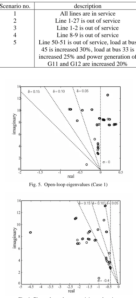
Fig. 5. Open-loop eigenvalues (Case 1)
[image:4.612.107.262.381.492.2]TABLEII
PSS PARAMETER SET OBTAINED BY THE PROPOSED METHOD
G1 G2 G3 G4 G5 G6 G7 G8 G9 G10 G11 G12 G13 G14 G15 G16
K 10.00 7.643 10.00 10.29 - 6.716 - 3.000 9.999 9.970 3.449 9.996 2.000 - 2.000 2.000
T1 0.079 0.094 0.048 0.080 - 0.080 - 0.080 0.050 0.171 0.173 0.001 0.001 - 0.040 0.030
T2 0.069 0.009 0.020 0.019 - 0.123 - 0.010 0.010 0.010 0.508 0.001 0.010 - 0.013 0.020
T3 0.080 0.080 0.192 0.105 - 0.080 - 0.158 0.050 0.078 0.075 0.079 0.001 - 0.05 0.001
Case 2
T4 0.010 0.011 0.010 0.028 - 0.020 - 0.054 0.020 0.020 0.010 0.004 0.011 - 0.083 0.010
K 3.447 7.642 6.488 10.29 - 6.959 10.73 6.087 11.91 13.15 3.449 14.46 20.00 17.62 15.08 23.87
T1 0.516 0.096 0.048 0.069 - 0.096 0.001 0.103 0.040 0.171 0.173 0.001 0.001 0.033 0.095 0.069
T2 0.069 0.009 0.036 0.026 - 0.125 0.001 0.004 0.085 0.013 0.007 0.001 0.057 0.044 0.045 0.059
T3 0.108 0.066 0.192 0.105 - 0.102 0.349 0.156 0.125 0.115 0.075 0.088 0.038 0.322 0.609 0.001
Case 3
T4 0.030 0.011 0.003 0.026 - 0.080 0.019 0.054 0.011 0.046 0.013 0.004 0.011 0.049 0.079 0.058
K 7.107 13.49 17.28 10.29 - 14.77 12.59 10.63 20.15 13.78 3.388 26.38 31.60 34.93 19.28 25.10
T1 0.528 0.096 0.017 0.068 - 0.094 0.001 0.133 0.040 0.202 0.177 0.001 0.001 0.001 0.001 0.342
T2 0.069 0.009 0.067 0.059 - 0.001 0.001 0.004 0.148 0.076 0.007 0.001 0.119 0.173 0.206 0.014
T3 0.009 0.116 0.191 0.119 - 0.213 0.215 0.156 0.164 0.119 0.075 0.088 0.038 0.421 1.608 0.011
Case 4
[image:5.612.70.269.51.210.2]T4 0.023 0.011 0.003 0.040 - 0.080 0.019 0.042 0.002 0.049 0.013 0.004 0.001 0.174 0.223 0.312
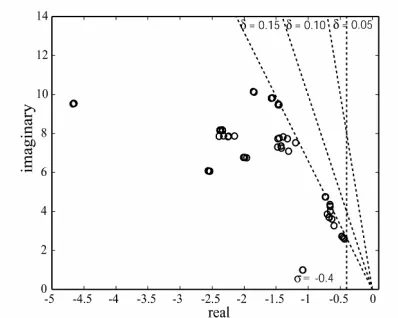
[image:5.612.69.274.250.407.2]Fig. 7. Eigenvalues relevant to minimum damping ratio 15% and damping factor -0.4 (Case 3)
Fig. 8. Eigenvalues relevant to minimum damping ratio 15% and damping factor -1.0 (Case 4)
The eigenvalues are plotted for four-case studies.
Case1-open-loop system (no PSS): It is obvious in Fig. 5 that system is very risky to be unstable. Many complex modes have minimum damping ratio less the requirement of 5%. Case 2-minimum damping ratio δ0 =5% and maximum
damping factor σ0=-0.4: Fig. 6 shows that all eigenvalues can
be shifted to stable zone based on specific requirements. PSS parameters and locations obtained by the proposed
method are shown in Table II. The result is similar to Rogers’ method [8]. However, by the proposed tuning method, only 13
PSSs are adequate to satisfy the minimal requirement of damping ratio while Rogers’s method requires 14 PSSs. Moreover, to satisfy two objectives at the same time is not an easy task. In other words, the proposed method is independent of complexity in predetermining the PSS locations and it simultaneously optimizes multiobjective function.
Case 3-minimum damping ratio δ0 =15% and maximum
damping factor σ0=-0.4: δ0 is increased from 5% to 15% by
keeping σ0 at constant -0.4. It can be seen in Fig. 7 that the
eigenvalues at frequencies higher than 6 rad/s can be improved significantly. However, by using only obj 1 in tuning process has minor effects in lower frequency modes. To improve the stability of these modes, optimizing relative stability by using obj 2 is a need. In addition, 15 PSSs are needed to improve the minimum damping ratio.
Case 4-minimum damping ratio δ0 =15% and maximum
damping factor σ0=-1.0: To see the effect by change of Obj 2,
damping factor is increased to -1.0 by keeping the minimum damping ratio constant at 15%. In Fig. 8, all eigenvalues at frequencies less than 6 rad/s can be shifted to have higher damping ratio. This can be said that low frequency modes can be significantly improved by using Obj 2. The effect of varying of Obj 2 at higher frequency is minimal. The eigenvalue analysis reveals that the close-loop plant performance is fitting in the area of specific requirements despite changing in the system conditions. This shows the superiority of PSS tuning by using the multiobjective function. The improvement of damping performance is not only at high frequency modes, but also at low frequency modes.
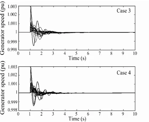
[image:5.612.61.561.600.735.2]Fig. 9 Generator speeds when fault occurs on line 1-2
Fig. 10. Generator speeds when fault occurs on line8-9
Fig. 11. Generator speeds when fault occurs on line1-27
based multiobjective function, lightly damped and undamped oscillation modes are able to be shifted to a specific stable zone in the s-plane and the appropriate PSS locations can be obtained simultaneously. The eigenvalue analysis confirms the improvement of close-loop plant performance. Additionally, non-linear time domain simulation confirms the effectiveness of obtaining PSSs by improving in dynamical oscillations.
VII. ACKNOWLEDGMENT
This work is supported by “The JSPS Postdoctoral Fellowship for Foreign Researchers” program from the Japan Society for the Promotion of Science (JSPS).
VIII. REFERENCES
[1] E. V. Larsen and D. A. Swann, " Applying Power System Stabilizers, Part I; General Concepts, Part II; Performance Objectives and Tuning Concepts, Part III; Practical Considerations", IEEE Trans. on Power Apparatus and Systems, Vol. PAS-100, pp. 3017-3046, 1981.
[2] P. Kundur, Power System Stability and Control, New York: McGrawHill, 1993.
[3] Y. L. Abdel-Magid, M. A. Abido, S. Al-Baiyat, and A. H. Mantawy, “Simultaneous Stabilization of Multimachine Power Systems Via Genetic Algorithms”, IEEE Trans. on Power Systems, Vol.14, No.4, pp.1428-1439, Nov 1999.
[4] A. L. B. do Bomfim, G. N. Taranto and D. M. Falcão, “Simultaneous Tuning of Power System Damping Controllers Using Genetic Algorithms”, IEEE Trans. on Power Systems, Vol.15, No.1, pp.163-169, Feb 2000.
[5] Y. L. Abdel-Magid and M. A. Abido, “Optimal Multiobjective Design of Robust Power System Stabilizers Using Genetic Algorithms”, IEEE Trans. Power Systems, Vo. 18, No. 3, pp. 1125-1132, Aug. 2003. [6] K. Hongesombut, Y. Mitani, and K. Tsuji, “An Automated Approach to
Optimize Power System Damping Controllers Using Hierarchical Genetic Algorithms”, Proc. of Intelligent System Application to Power Systems, pp.3-8, June 2001.
[7] K. Hongesombut, Y. Mitani and K. Tsuji, " Simultaneous Tuning of Power System Stabilizers Based on a Combined Method of a Micro-GA, HGA and Minimum Phase Control", Trans. IEE of Japan, Vol. 122-B, No. 12, pp. 1270-1277, Dec. 2002.
[image:6.612.51.293.496.695.2]