Design Synthesis and Shape Generation
Alison McKay1, Scott Chase2, Steven Garner3, Iestyn Jowers1, Miquel Prats3, David Hogg4, Hau Hing Chau1, Alan de Pennington1, Christopher Earl3, Sungwoo Lim5
1 Background
Today’s computer aided design systems are based on underlying technologies developed over 20 years ago. Although they have become a key part of the design process, and are ubiquitous in industrial product development processes, they usually come into play after the shape of the design has been created. In essence, today’s CAD systems are used to support design evaluation and analysis, and downstream applications such as manufacturing. Our research challenge was to bring computers into the start of the creative design process, where they can augment design activity by supporting design synthesis: enhancing and highlighting options that might be open to the designer. Our vision was of a computer aided design synthesis system that can work with and manipulate designers’ sketches at the earliest stage of the design process. Previous research in the application of shape grammars to design generation indicated that they offered a potential foundation upon which such a system could be built. Since first proposed in the early 1970s, a number of shape grammar-based design systems have been built. All, however, have struggled to find a way to identify automatically key elements of a shape, so-called “sub-shape detection”. Sub-shape detection is essential to the automation of the shape grammar technology and, therefore, the realization of usable computer aided design synthesis systems.
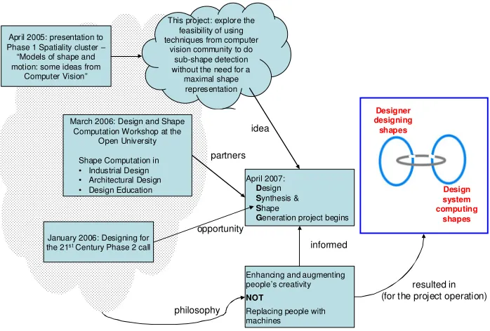
The genesis of the project (illustrated in Figure 1) can be traced back to three events:
David Hogg made a presentation to the Designing for the 21stCentury Phase 1 cluster on Spatiality in April 2005 entitled “Models of shape and motion: some ideas from Computer Vision”. It was during his presentation that the initial idea for the project was identified, that is, exploring the feasibility of using computer vision techniques for sub-shape detection with a view to avoiding the (problematic) maximal shape representation typically used in shape grammar implementations.
The majority of what would become the project team (with backgrounds in design, sketching and shape grammars) participated in the workshopDesign and Shape Computationat the Open University in March 2006. Discussions explored shape computation in industrial and architectural design, and design education and resulted in a proposal to study how designers generate shapes through sketching, with comparisons between different design disciplines.
The Designing for the 21stCentury Phase 2 call for projects was released in January 2006. In response the project team put forward a two-pronged research proposal building on the idea of a framework of two shape generation cycles, one driven by human designers and the other by a computer-based shape generation system, connected by a third cycle of communication (Figure 1). This framework served as an organising structure for all major project activities and events.
1School of Mechanical Engineering, University of Leeds
2Department of Architecture, University of Strathclyde (moved to Department of Design, Manufacture and
Engineering Management soon after the end of the project)
3Department of Design, Development, Environment and Materials, The Open University 4School of Computing, University of Leeds
5Department of Architecture, University of Strathclyde (moved to Department of Civil and Building Engineering,
Loughborough University the end of the project)
published in Inns, T, 2009 Designing for the 21st Century: Interdisciplinary Methods and Findings (Gower Publishing) Final pre-publication version. Details of the definitive version are available at
This project: explore the feasibility of using techniques from computer
vision community to do sub-shape detection without the need for a maximal shape representation April 2005: presentation to
Phase 1 Spatiality cluster – “Models of shape and motion: some ideas from
Computer Vision”
March 2006: Design and Shape Computation Workshop at the
Open University Shape Computation in • Industrial Design • Architectural Design • Design Education
January 2006: Designing for the 21s tCentury Phase 2 call
April 2007:
Design
Synthesis &
Shape
Generation project begins
idea
opportunity partners
Enhancing and augmenting people’s creativity
NOT
[image:2.595.135.484.116.352.2]Replacing people with machines philosophy informed Designer designing shapes Design system computing shapes resulted in (for the project operation)
Figure 1: The research project formation
2 Context
Currently available computer aided design systems enable the creation of digital product definitions. Digital product definitions are created after the bulk of [shape] designing has been finished because their creation requires a detailed knowledge of the shape that is to be defined. They offer benefits by providing information for downstream processes such as analysis and manufacturing. Enhancing the act of
designing itself requires understanding of how designers create design shapes in the first place (Prats and Earl, 2006) rather than how the results of their designing might be represented. To this end, this project addressed the questions:
1) How do designers, across a range of disciplines, generate shapes? and 2) What similarities and differences in approach can be observed?
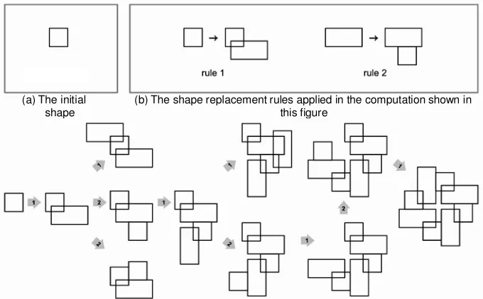
(b) The shape replacement rules applied in the computation shown in this figure
(a) The initial shape
[image:3.595.132.472.121.332.2](c) A fragment of the network of shapes that can be computed through application of the shape rules.
Figure 2: A simple two rule shape grammar
The application of a shape rule involves two key steps. Firstly, the shape on the left-hand side of a rule must be identified in the shape from which a new shape is to be computed; this is referred to as “sub-shape detection”. For example, the initial “sub-shape in Figure 2(a) can be seen on the left hand sides of the shape rules in Figure 2(b). Secondly, the rule is applied by replacing the sub-shape from the left-hand side of the rule with the shape on the right-hand side of the rule. In the majority of shape grammar implementations (and for limited kinds of shape and shape rule), once a sub-shape has been detected, the system can automatically apply a rule. However, the sub-shapes have to be identified manually because the automatic detection of sub-shapes is an open research question within the shape grammar community.
Significant efforts around the world are being directed towards creating analytic solutions to the sub-shape detection problem but progress is slow. A key to the DSSG project was the idea that sub-sub-shape detection might be achieved through the application of computational approaches that have been established in the computer vision community. In contrast to analytic approaches, which search for shapes in the mathematical representation of a shape, the method used in this research regarded sub-shapes as visual objects derived from a shape’s mathematical representation. This has proved to be a groundbreaking approach and was directed by an additional question:
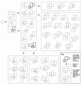
3) Can computer vision techniques be used to resolve the sub-shape detection problem? A key benefit of solving this problem is that it opens up the possibility to compute large networks of shapes, facilitating exploration of more avenues of possible shapes by designers. The size of the potential shape networks is vast. An example using the initial shape and rules from Figure 2 is given in
Error! Reference source not found.Figure 3. At each step in the computation a designer would select the shape (highlighted in black in Figure 3) from which new shapes would be computed. This led to our final research question, namely:
Figure 3: A network of pathways through a solution space
3 Research Journey
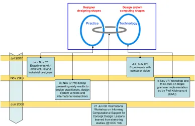
The major project activities corresponded to the two shape generation cycles shown in Figure 4: practice (designer designing shapes) and technology (design system computing shapes). They were
Nov 2007
Designer designing shapes
Design system computing shapes
16 Nov 07: Workshop and think-tank on shape grammar implementation led by Prof Krishnamurti
(CMU) 30 Nov 07: Workshop
presenting early results to design practitioners, design
system vendors and international researchers
Practice Technology
Jul 2007
Jul - Nov 07: Experiments with architectural and industrial designers
Jul - Nov 07: Experiments with
computer vision
Jun 2008 21 Jun 08: International
Workshop on Informing Computational Support for Concept Design: Lessons learned from sketching
[image:5.595.104.492.104.355.2]studies (@ DCC ‘08)
Figure 4: The research journey
Investigation of the technology cycle, in response to the third research question6, resulted in the development of a software prototype shape generation system built using a shape grammar paradigm and based on computer vision technology. Throughout the project we ran several workshops with various goals, focusing on the different design cycles in our framework.
The first, in November 2007, was an internal project think-tank led by visitor Prof. Ramesh Krishnamurti (Carnegie Mellon University). This focused on the technology cycle (design system computing shapes) with discussions of computer implementations of grammar based design systems.
The second workshop, also in November 2007, presented early results with the aim to obtain feedback from a selected group drawn from an international cohort of design practitioners, design system vendors and design researchers. While this covered all aspects of the project, the main discussion centred on the interaction between designer and system cycles (the communications cycle). A number of the participants expressed interest in testing the software prototype and possible future collaboration.
The final workshop,Informing Computational Support for Concept Design: Lessons Learned From Sketching Studies,was delivered as part of theDesign Computing and Cognition ‘08conference and focused on the practice cycle (designer designing shapes). A data set from our sketching
experiments was provided in advance to the workshop attendees, with the goal being to explore how this data could be analysed so as to inform the development of software intended to support
conceptual design. (http://www.engineering.leeds.ac.uk/dssg/informing_cacd.html)
As validation of the project concepts, we also produced a video demonstrating our vision of how a designer might use the shape generation software to aid conceptual design (downloadable from the project website7or YouTube8). The remainder of this section describes the research journey in each of the three cycles.
3.1 Designers designing shapes
Two research methods were blended together to provide effective and valuable descriptions within the context of the research: traditional methods, such as interviews and video records of designers
undertaking sketching tasks (Lawson, 2004), and formal methods, namely shape rules (Stiny, 2006), as a way to formally describe shape transformations.
Sketches were analysed based on their geometric properties. However, sketches are more than a grouping of abstract shapes; they carry semantic information. The meanings attached to shapes in a sketch can be ambiguous and dynamic, changing as a result of new interpretations of the sketch or design problem (Purcell and Gero, 1998). The development of computational systems that can adapt to different perceptions of what a given sketch might represent and so contribute to the process of design exploration is problematic. One step to realising such systems involves understanding how shapes, as geometric objects, are manipulated in sketches independently of their meaning. This understanding could lead to computational systems that provide affordances more suitable for creative design than is currently available in CAD systems.
A design representation such as a sketch can be perceived in many different ways. Each interpretation leads to a decomposition of the shape into elements, with relations among elements yielding starting points for the exploration of variations through the generative description of designs (Stiny, 2006). Based on this sequence we chose to run three design tasks as means of exploring factors that are particularly significant in the process of shape transformation in explorative sketching: shape decomposition, shape reinterpretation, and design families.
The three design tasks each involved designers sketching. Eight professional industrial designers, four professional architects and two researchers in the field of architecture participated in the study. The participants were video recorded as they carried out the design tasks. Participants produced their sketches using an A4 paper-based digital notepad; this gave the dual advantage of resembling a
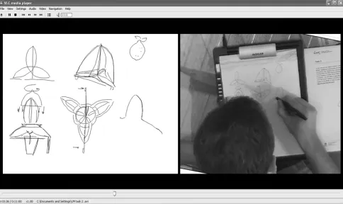
[image:6.595.177.419.437.581.2]traditional pencil-and-paper environment whilst facilitating the recording of pen stokes via screen capture software. At the end of the experiment participants were shown their sketches and asked to report their design movements. An example of the data recorded through the experiments is given in Figure 5.
Figure 5: Two synchronised videos, left, sketches taken from the digital notepad and, right, video recording of hand movements
The first task, based on the work of Van Sommers (Van Sommers, 1984), was intended to examine whether stroke-sequence whilst sketching is related to interpretation and decomposition. Two groups of subjects were asked to begin by copying the abstract shapes given in Figure 6(a), which were presented as logos, and then to develop them according to a given design brief. Each subject was given one of two design briefs, each giving different meanings of the logos depicted, and allowed 10 minutes to complete the task.
The goal of the second task was to encourage a variety of interpretations of a shape leading to different sub-shape compositions. In order to achieve this, the participants were presented with an initial design proposal which was rich in suggestion, namely, the triquetra shown in Figure 6(b). The design brief the participants were asked to respond to was dependent on their design discipline. The industrial designers were introduced to the triquetra as a concept design for a lemon squeezer, while the architects were introduced to the same shape as a conceptual design for a building. The analysis here sought to examine the extent to which a given meaning led to different paths of exploration and types of shape
transformations. Participants had 10 minutes for this task.
The third task provided a more explicit initial design in order to keep participants centered on one
particular design proposal and thus produce larger design families. This intentionally offered less freedom in interpretation than the second task with the two alternative shapes shown in Figure 6(c), a concept for a kettle design (for the industrial designers) and a new building (for architects), being used as starting points. Participants had 15 minutes for this task.
(a) (b) (c)
Figure 6: (a) crossed swords / two mice sniffing and cocktail glass with cherry / person with telescope; (b) Triquetra; (c) Kettle and St Mary Axe
3.2 Design system computing shapes
Providing computational support for conceptual design is challenging because designers require a fluid and dynamic interaction with their design representations in order to support creative design exploration (Tovey, 1989). It has been proposed that generative systems of design, such as shape grammars, could enhance the creative processes of designers by exposing them to previously unimagined opportunities for exploration (Woodbury and Burrow, 2006). However, implementing shape grammars is difficult because they depend on visual representations of shapes that are independent of their underlying structure. This means that it is necessary to compare shapes according to their visual qualities, regardless of their mathematical representation.
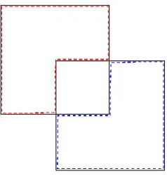
[image:7.595.95.516.267.396.2]Figure 7: Two overlapping squares?
Previous approaches to shape grammar implementation have relied on analytical techniques for sub-shape detection. Such techniques are made possible by reducing sub-shapes to maximal representations that enable mathematical comparison. However, such techniques are only applicable to shapes composed of specific geometric elements such as straight lines or parametric curves and a general approach for sub-shape detection has not previously been proposed. In addition, a key premise in the application of sub-shape grammars lies in the fact that the shape to which a rule might be applied, and so in which sub-shapes are to be detected, is a visual entity. When humans search for a sub-shape, visual similarity implies equality whereas when analytical techniques carry out the same process visual similarity does not necessarily imply equality.
In the DSSG project, an approach to sub-shape detection was explored where it was viewed not as a problem to be solved analytically but, instead, as a problem of computer vision. Computer vision (Forsyth and Ponce, 2003) is concerned with developing algorithms and computational systems that obtain information from images. In particular, object recognition is a sub-domain of computer vision that is concerned with finding a target object in an image or video sequence, and is applied to a range of problems including fingerprint matching and character recognition. A key premise of the DSSG project was that sub-shape detection can be viewed as a kind of object recognition problem. In contrast to analytic approaches, which search for sub-shapes in the mathematical representation of a shape, the methods used in object recognition look for sub-shapes in visual objects that are derived from a shape’s mathematical representation.
3.3 Interactions between designers and design systems
The interaction between designer and shape generation system has always been a difficult one. Implementers of shape grammar systems have struggled not only with the computational issues in sub-shape recognition, but also in the ways to present sub-shapes, designs and rules to the designer in a manner that allows them to be easily viewed, chosen and manipulated without hindering the creative process. Chase (Chase, 2002) presents a model for interaction with a grammar system throughout the stages of its development and use, referring to the actors involved (e.g. system, developer, end user/designer). Our research framework (see Figure 4) represents two actors in this process, the designer and the shape generation system. Through our workshops and other discussions, we found it to be an effective vehicle for engagement with stakeholder communities such as potential developers and users of future shape synthesis systems, and researchers from other institutions. It was used to facilitate the establishment of priorities for later stages of the project. Our demonstration video depicts part of this process, in which the designer passes a ‘designed’ shape to the system, then utilises the system for further shape manipulation to generate a network of new shapes. Any of these generated shapes could then be used by the designer for their further design activities. As validation of this interactive approach, we encoded typical
transformation rules (e.g. outline transformation, add/cut/replace element) identified through analysis of the sketch data set into the software. We then tested the system with shapes and replacement rules typical of those used in shape grammars, developing examples illustrating how the system could
Subsequent to the project’s completion, an additional workshop was run with Spanish product design students in which, given a set of designs, a group of students generated design rules, then passed them to another group to generate new designs.The new designs were then compared with the original
designs in order to evaluate whether or not they belonged to the same style. This sharing of shapes and rules between the two groups provides some insight into our ‘dual actor’ communications framework in which shapes are shared between designer and system. One project publication (Lim et al., 2008b) reports on the customisation of designers’ preferences using shape rules. This preliminary investigation suggests ways in which a designer could interact with a shape generation system in order to target certain types of designs.
4 New knowledge and understanding
The DSSG project has generated new knowledge and understanding about design synthesis and shape generation. It has created and tested a prototype tool that applies our understanding of the importance of shape transformation to the visual strategies of shape exploration seen in design practice. The work has also highlighted shortcomings and identified future work that is needed. Following the research
framework presented in Figure 4, the contribution of the project can be outlined under three headings:
Designers designing shapes
Design system computing shapes
Interactions between designers and design systems
4.1 Designers designing shapes
Transformation through shape rules
The collection of sketches, videos and interviews gathered in the study allowed the identification of common transformations applied to sub-shapes in sketches. It is proposed that such shape
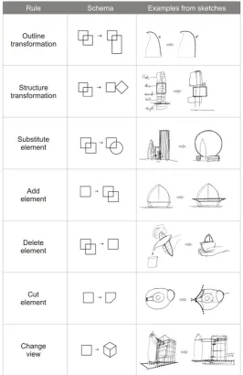
transformations can be described via a limited number of general shape rules. Figure 8 illustrates seven general rules:outline transformation,structure transformation,substitute element,add element,delete element,cut element, andchange view.
The experiments demonstrated that, given this limited number of shape rules, it is possible to explicitly describe shape transformations between successive sketches. These appear to be key graphic devices for design exploration. Early results indicate that the explorative strategies of designers are tuned to look for sub-shapes and their recognition, repetition and modification mark important iterations in creative shape transformation and development. Shape rules offer a means to capture information not embedded in sketches which might be useful for the recording, reflection, and reuse of previous ideas. Every shape transformation made by participants from both disciplines – architecture and industrial design – can be described with general rules in the set. This is what they have in common. However, more research is required to correctly compare design disciplines in terms of shape transformations. This is due to the difficulty of identifying designers’ shape interpretations at any given transformation. The collection of rules presented in Figure 8 is not exhaustive and more general rules may be identified through further research. For example, the rules capture kinds of shape transformation observed in the experiments; additional rules would be needed to describe the actual shape transformations made by designers.
Another conclusion that can be drawn from this study is that it is not straightforward to accurately
Figure 8: General shape rules
4.2 Design system computing shapes
In shape grammar-based systems, can computer vision techniques be used to resolve the sub-shape detection problem?
Figure 9: Example of an implemented shape grammar
Early results indicate that such a system could capture the benefits of the shape grammar formalism by both allowing designers freedom to explore design concepts via manipulation of sub-shapes and presenting networks of design alternatives which have been generated via applications of shape rules. Such a system would not replace the creativity of a designer by automatically generating completed design concepts but instead would assist the designer by suggesting alternatives, and possibly unconsidered avenues of exploration.
4.3 Interactions between designers and design systems
How might the ability to compute shapes enhance the act of designing itself?
While the contributions made regarding design practice and technology are valuable, the project members were most excited by the new understanding of the third cycle in the research framework, that is, the cycle that links these two phenomena. Understanding mechanisms by which the two domains might interact is likely to provide significant long-term benefit of the work.
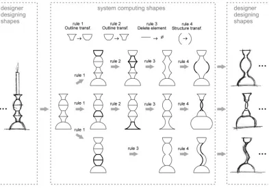
The DSSG research framework assists the examination of mechanisms used by designers in recognising and transforming design structures. If such mechanisms could be realised it would also be possible to develop a more independent system that scrutinises designers’ freehand drawing, seeking to offer potentially valuable transformations. A hypothetical example, illustrated in Figure 10, shows how, given an initial concept, a system computing shapes can automatically generate alternatives that could be useful to designers. These alternatives are achieved by application of rules to different sub-shapes found in the design.
[image:11.595.73.466.424.700.2]If this parsing of the sketching process could take place in real time it might provide a useful stimulus to the creative generation and development of shape and form. In order to develop such mechanisms it is necessary to consider not only the technical issues of recognising and manipulating perceived structures in a design but also the modes in which they could be implemented in a computational system intended to support design exploration (McKay et al., 2008). Such modes should take into account the mechanisms of shape transformation commonly utilised by designers when sketching so that they may be able to use them in ways that are cognitively comfortable (Cross, 2006).
5 Concluding remarks
Our vision for the use of a computer aided design synthesis system is represented by the three interlinked cycles in our research framework. The designer designing shapes and the system computing shapes are independent of each other and joined by a third cycle of communication between the two. Information flowing from the designer to the computational system is envisioned to be in the form of commonly used design descriptions, such as sketches and in the form of shape rules. Information flowing back to the designer will be essentially visual in the form of lattices of computed shapes that prompt and inspire the designer. The communication cycle is critical in order to ensure a fluid interaction between designer and computer. The primary problem at present is the relatively slow speed of the cycling through this model. Ways to support design thinking at something like the speed that human participants have come to expect in creative designing are required. Research is now underway exploring the integration of the DSSG results with eye tracking technology9. It is hoped that eye tracking technology will provide a fast and cognitively comfortable means by which sketches of interest to designers can be identified during the creative process and transformed in real-time to assist their design and development thinking.
References and reading lists
ANTONSSON, E. K. and CAGAN, J. (2001)Formal engineering design synthesis,Cambridge, UK; New York, Cambridge University Press.
BILDA, Z. and DEMIRKAN, H. (2002) An insight on designers' sketching activities in traditional versus digital media. Design Studies,24,27-50.
CHASE, S. C. (2002) A model for user interaction in grammar-based design systems.Automation in Construction, 11, 161-172.
CROSS, N. (2006)Designerly Ways of Knowing, Springer, London, UK.
DO, E. Y.-L., GROSS, M. D., NEIMAN, B. and ZIMRING, C. (2000) Intentions in and relations among design drawings.Design Studies,21,483-503.
FORSYTH, D. A. and PONCE, J. (2003)Computer Vision: A Modern Approach, Prentice Hall. GOEL, V. (1995)Sketches of thought, MIT Press, Cambridge, MA.
JOWERS, I., PRATS, M., LIM, S., MCKAY, A., GARNER, S. W. and CHASE, S. (2008) Supporting reinterpretation in computer-aided conceptual design.Fifth Eurographics Workshop on Sketch-Based Interfaces and Modeling (SBIM'08) <http://www.dgp.toronto.edu/%7Ekaran/sbim/>.Annecy, France. KNIGHT, T. W. (1994)Transformations in Design: A Formal Approach to Stylistic Change and Innovation in the Visual ArtsCambridge University Press, Cambridge, England.
LAWSON, B. (2004)What Designers Know,London, UK, Architectural Press.
LIM, S., PRATS, M., CHASE, S. and GARNER, S. W. (2008a) Sketching in design: formalising a transformational process. Computer Aided Architectural Design and Research in Asia (CAADRIA'08). Chiang Mai, Thailand.
LIM, S., PRATS, M., JOWERS, I., CHASE, S., GARNER, S. W. and MCKAY, A. (2008b) Shape exploration in design: formalising and supporting a transformational process.International Journal of Architectural Computing,4,415-433.
LIM S., P. M., CHASE S., GARNER S., (2008) Categorisation of designs according to preference values for shape rules. IN J S GERO, A. K. G. (Ed.)Third International Conference on Design Computing and Cognition (DCC'08)Georgia Institute of Technology, Atlanta, USA, Springer.
LIU, Y. (1995) Some phenomena of seeing shapes in design. Design Studies,16,367-385.
MCKAY, A., JOWERS, I., CHAU, H. H., DE PENNINGTON, A. and HOGG, D. C. (2008) Computer aided design: an early shape synthesis system. International Conference in Advanced Design and Manufacture (ICADAM'08).Sanya, China.
PRATS, M. and EARL, C. F. (2006)Exploration through drawings in product design Design Computing and Cognition.Eindhoven: Springer.
PRATS, M., LIM, S. and JOWERS, I. (2008) Describing shape transformations in design sketches Informing Computational Support for Conceptual Design Workshop @ Third International Conference on Design Computing and Cognition (DCC'08).Georgia Institute of Technology, Atlanta, USA.
PRATS, M., LIM, S., JOWERS, I., GARNER, S. W. and CHASE, S. ( accepted for publication) Transforming shape in design: Observations from studies of sketching. Design Studies DOI:10.1016/j.destud.2009.04.002
PURCELL, A. T. and GERO, J. S. (1998) Drawings and the design process.Design Studies19,389-430. SAUND, E. and MORAN, T. P. (1994) A perceptually-supported sketch editor. ACM Symposium on User Interface Software and Technology.Marina del Rey, CA.
SCHÖN, D. A. and WIGGINS, G. (1992) Kinds of seeing and their functions in designing.Design Studies, 13,135-156.
STINY, G. (2006)Shape: Talking about seeing and doing, MIT Press, Cambridge, MA. TOVEY, M. (1989) Drawing and CAD in Industrial Design. Design Studies,10,24-39.