Riyaz Fatkullin1,2,*, Sergey Bogomolov2, Konstantin Kuzmenkov2 and Andrey Efremov2 1Institute for Theoretical and Experimental Physics (ITEP), 117218, Moscow, Russia
2Flerov Laboratory of Nuclear Reactions (FLNR JINR), 141980, Dubna, Moscow region, Russia
Abstract. 2.45 GHz ECR ion sources are widely used for production of protons, single charged heavy ions and secondary radioactive ion beams. This paper describes the development of a compact ECR ion source based on 2.45 GHz coaxial resonator. The first results of extracted current measurements at different resonator configuration as a function of UHF frequency, power and gas flow are presented.
1 Introduction
Several ECR ion sources for production of radioactive ion beams operating at 2.45 GHz were developed at the Flerov Laboratory of Nuclear Reactions (FLNR JINR) [1]. Such ion sources are used for production of 6He+ ions in the DRIBs project [2] and at the MASHA
mass-spectrometer [3]. The magnetic system of such sources is composed of NdFeB permanent magnet rings, and it provides the creation of pseudo-closed resonant surfaces (875 Gs). The plasma chamber of such sources is based on a single-mode cylindrical resonator with an internal diameter of 90 mm and a length of 100 mm. The measured gas efficiency of those sources is about 90% for noble gases (Ar, Kr). The transformation time of atoms into ions of this ion source has not been investigated yet, however, according to the results of paper [4], this time decreases with the decrease of the plasma chamber volume.
The volume of plasma chamber can be reduced if the chamber will be based on a coaxial resonator loaded with a capacitor. Pseudo-closed surfaces should be located in the gap of the capacitor to achieve optimum conditions for plasma confinement.
1.1 Development of compact ECR ion source
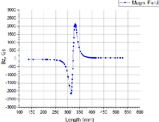
The schematic structure of the source is shown in Fig.1. The magnetic system of the source is composed of a radially magnetized ring with an external diameter of 52 mm, an inner diameter of 22 mm and a thickness of 10 mm. The distribution of the magnetic field on the axis of the ring is shown in Fig. 2, the lines of an equal field are shown in Fig. 3. It can be seen that this magnetic system provides creation of pseudo-closed surfaces with a field level from 875 Gs up to 1750 Gs.
Fig. 1. Schematic view of the ECR ion source based on a coaxial resonator. 1 - central conductor of a coaxial resonator; 2 - resonator casing; 3 - magnetic ring; 4 - closed surfaces of the magnetic field; 5 - extraction hole.
Fig. 2. Axial magnetic field distribution of a ring magnet.
Fig. 3. The lines of equal magnetic field
The plasma chamber of the source represents the quarter wave resonator. The results of the resonator modeling are described in paper [5]. Based on the modelling results, an ECR ion source was designed and manufactured. Assembly drawing of the source is presented in Fig. 4. The view of the source is presented in Fig.5.
For changing the resonator gap three sets of the replaceable internal parts of resonator and replaceable plasma electrodes were used, providing the gap sizes of 5, 8 and 10 mm. The diameter of the extraction hole in plasma electrodes is 2 mm.
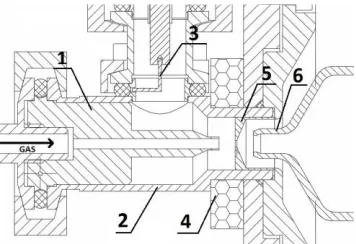
Fig. 4. Assembly drawing of ECR ion source based on a coaxial resonator: 1 - replaceable internal part of the resonator, 2 - external part of the resonator, 3 – coupling loop, 4 – permanent magnet ring, 5 - replaceable plasma electrode, 6 - pulling electrode.
Fig. 5. The view of ECR ion source: 1 – coaxial input, 2 – magnet ring, 3 – plasma electrode, 4 - resonator
2 Experimental stand and tests
Test of the source included: measuring of the extracted ion current at different gap sizes, gas flow and experimental definition of minimum discharge ignition power at different generator frequencies. Ar, Ne and He were used as working gases.
2.1 Experimental stand
The source was mounted on the DN160 flange and connected to the vacuum volume pumped by the 150 l/s turbopump providing the base vacuum about of 1.5 ÷ 3.0×10⁻⁶ torr.
During the source operation the pressure in vacuum chamber was about of 1.2x10⁻⁵ torr.
Solid state UHF generator with the output power up to 100 W in the frequency range of 2.4
÷ 2.5 GHz was used to feed the source. The UHF power was fed to the coupling loop through a coaxial cable and tuner. Control of the gas flow was performed by the piezoelectric leak valve controlled by the high voltage power supply (up to 1500 V). A negative potential about of 300 V was applied to the pulling electrode. During tests the current of ions incident on the pulling electrode was measured. The distance between the plasma electrode and pulling electrode equals to 5 mm in all experiments.
2.2 Results
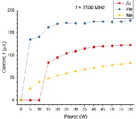
Fig. 6. Dependence of the ion current on the injected power for different gases.
Fig. 7 presents the dependence of the ion current on the gas flow at 2450 MHz and 20 W of injected power. The resonator gap equals to 8 mm. By varying the gas flow, one can tune the source for the maximal value of ion current.
Fig. 7. Dependence of the Ar ion current on gas flow.
The dependence of the ion current on the frequency of the generator was measured for various resonator gaps (Fig. 8). For all values of resonator gap the current increases with the frequency of generator. The highest current was produced with resonator gap of 8 mm.
Fig. 8. Dependence of the ion current on the generator frequency.
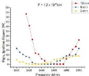
The dependence of the minimal ignition power on the generator frequency was investigated for various gaps at fixed gas flow (Fig. 9). It was possible to establish that in a certain frequency range 2450 ÷ 2465 MHz for 10 mm gap, 2430 ÷ 2460 MHz for 8 mm gap and 2425 ÷ 2435 MHz for 5 mm gap, the lowest power (about of 0.5 W) required for ignition is observed. The average required power over the whole range is minimal for 5 mm, maximal for 10 mm.
Fig. 9. Dependence of ignition power on the generator frequency.
3 Discussion
From the experimental data it can be concluded that the optimal value of the coaxial resonator gap is 8 mm. With this configuration of the source the highest extracted current was measured. Moreover, in this configuration of the source the minimal value of power for discharge ignition (about of 0.5 W) is maintained in a wider frequency range (2430 ÷ 2460 MHz) than for others gaps value. Extracted current increases with the power and shows slight saturation for He and Ar for the power above 25 ÷ 30 W.
The extracted current increases with the frequency for all values of resonator gap without noticeable saturation. It can be explained by the increase of resonance surface with the increase of frequency and shortening the distance between the resonance surface and plasma electrode.
The setting of the source for the maximal extracted current requires the fine tuning of the gas flow. The minimal gas flow, which allows maintain discharge corresponds to vacuum chamber pressure about of 4.2 x 10⁻⁶ torr.
The highest current produced in these experiments constitutes about of 180 µA for He. The further increase of the extracted current can be achieved by the increase of the extraction hole diameter and the frequency.
Conclusions
Compact and low power ECR ion source was designed and tested. The source is suitable for production of low and medium currents of singly charged ions. The further study will include the measurement of ions spectrum generated by the source, measurements of the gas efficiency and time response of the ion source. The beam quality should be also studied because it is an important feature of the ion source.
References
1. A. Efremov et al. Nucl. Instr. Meth. Phys. Res. B 204, 368–371 (2003)
2. Yu. Ts. Oganessian, Proc. of the Int. Conf. Nuclear shells – 50 years, Dubna, Russia, 1999, World Scientific, 2000, p61.
3. Yu. Ts. Oganessian et al. Nucl. Instr. Meth. in Phys. Res. B 204, 606–613 (2003) 4. P. Jardin et al. Nucl. Instr. Meth. Phys. Res. B 204, 377–381 (2003)