Volume 8, No. 5, May – June 2017
International Journal of Advanced Research in Computer Science RESEARCH PAPER
Available Online at www.ijarcs.info
Metropolitan Beacon System with Efficient Encryption Bit for Payload
Taruna Kumari
Department of CSE, SEST Jamia Hamdard, New Delhi, IndiaSuraiya Parveen
Department of CSE, SEST Jamia Hamdard, New Delhi, IndiaAbstract: This paper explains the Metropolitan Beacon System (MBS) system and the encryption of payload in an efficient way. The System MBS, gives a precise, reliable, consistent positioning system indoors and in urban scenario, where GNSS/GPS solutions are not effective or denied. MBS system framework along with 2-D accuracy, also provides highly resolved and exact location in the vertical dimension also, Which is unlike GPS System which were used for horizontal tracking only, The above Enhancement is done with the help of embedded sensors deployed in MBS system. This system technique provides a very fast jitter time which is actually time to first fix (TTFF), on the order of ~6 seconds under first start condition. Alike GNSS, MBS technology permits location tracking and computation on the device without any network dependency which permits wide variety of independent applications. For encryption the redundant bits on packets are used as encryption bits which enhances the encryption efficiently and without decreasing the payload bits of increasing the packet size.
Keywords: Metropolitan Beacon System (MBS), Augmentation, Leap seconds, Billing server, GPS satellite, Augmentation, Leap seconds,
Billing server, GPS satellite, Typographical, Encryption, User Estimate (UE).
I. INTRODUCTION
When we are under open sky a GPS/GNSS can easily tell us our location but what if we are inside a sky scrapper building. How anybody can locate our position. If we are in one of the room of that building and suddenly there is an emergency, how would the Police or medical emergency team will trace our exact location within that crucial time frame and respond to the emergency. Metropolitan Beacon System (MBS) is the solution and the new era location tracking solution for the problem.
The goal of the MBS system is to provide high precision, reliable, consistent positioning system providing high accuracy indoors and in urban canyons where it is challenging to get any reliable position using GPS or other wide area reliable technologies.
This paper explains the Metropolitan Beacon System (MBS) system and the encryption of payload in an efficient way. MBS system framework along with 2-D accuracy, also provides highly resolved and exact location in the vertical dimension also, Which is unlike GPS System which were used for horizontal tracking only, The above Enhancement is done with the help of embedded sensors deployed in MBS system. This system technique provides a very fast jitter time which is actually time to first fix (TTFF), on the order of ~6 seconds under initial start condition. Alike GNSS, MBS technology permits location tracking and computation on the device without any network dependency which permits wide variety of independent applications. For encryption the redundant bits on packets are used as encryption bits which enhances the encryption efficiently and without decreasing the payload bits or increasing the packet size.. The signal structure of MBS is designed so that the signal processing entities of a standard GPS receiver’s baseband can be reused. This architecture also allows for hybridization with other GNSS constellations. High Level Architecture of The MBS Network consists of a network of highly synchronized beacons that broadcast radio signals in the M-LMS band.
II. LITERATURE REVIEW
A. Basic concept of GPS
• Fundamentals: The GPS[1] concept relies on time. The satellites carry very stable atomic clocks that are synchronized to each other and to ground clocks. In case of variation from true time on ground is corrected daily.
A GPS receiver use data of multiple satellites and solves equations to determine the actual position of the receiver and its difference from true time. At a minimum, 4 satellites should be in view of the receiver so that it compute 4 unknown parameters (1 clock deviation and 3 position coordinates from satellite time).
”.
B. More detailed description
Every GPS satellite continually broadcasts a signal (modulated carrier frequency) that is:
• A pseudorandom code (sequence of 1`s and 0`s) which is known to the receiver. By time-aligning a generated version and the receiver-measured version of that code, the time of arrival (TOA) of a defined point (called epoch) in the code sequence, can be tracked in the receiver clock time scale. A message which has the “time of transmission”(TOT) of epoch code (which is actually time scale in GPS system) and the position of satellite at that time.
4 TOFs.In real practice the receiver position (in 3D Cartesian coordinates given origin at the Earth's center) and the offset of the receiver Watch relative to the GPS time are computed simultaneously, using the navigation equations for processing of the TOFs.
C. Accuracy enhancement and surveying
• Augmentation: Including external information
into the calculation process can improve accuracy. This kind of augmentation[2] systems are generally referred based on how the data arrives. Some of the systems transmit extra error information (example clock drift, ionospheric delay), others characterize prior errors, while a 3rd group provides additionally required navigational or vehicle information. Examples of augmentation systems include the Wide Area Augmentation System (WAAS), European Geostationary Navigation Overlay Service (EGNOS),Differential GPS (DGPS), Inertial Navigation Systems (INS) and Assisted GPS. The standard accuracy of about 15 meters (49 feet) can be augmented to 3–5 meters (9.8–16.4 feet) with DGPS, and to about 3 meters (9.8 feet) with WAAS.[4]
• Precise monitoring: Accuracy can be enhanced
through precise monitoring and measurement of existing GPS signals in additional or alternate ways. The largest error generating reason is usually the unpredictable delay through the ionosphere. The spacecraft broadcast ionospheric model parameters, but some errors left there. This is one reason GPS spacecraft transmit on 2 different frequencies, L1 and L2. Ionospheric delay is a well-defined function of the total electron content (TEC) and frequency along the path, so measuring the arrival time difference between the frequencies in turn determines TEC and thus the precise ionospheric delay at each frequency is calculated. Military or defence receivers can decode the P(Y) code transmitted on both L1 and L2. Without using decryption keys, it is somewhat possible to use a codeless technique to compare the P(Y) codes on L1 and L2 to get much of the same error information. However, this technique is not that fast, so it is currently available only on specialized surveying equipment. In the future, additional civilian codes are expected to be transmitted on the L2 and L5 frequencies, All of the users will then be able to perform dual-frequency measurements and directly compute ionospheric delay errors.[3]An another form of precise monitoring is called Carrier-Phase Enhancement (CPGPS). This monitoring system rectifies the error which comes up because of the pulse transition of the PRN which is not instantaneous, and thus the correlation (satellite-receiver sequence matching) operation is not perfect. CPGPS uses the L1 carrier wave, which has a period of 1s/(1575.42*106
C/A Gold code bit period of 1s/1023*10
) ~ = 0.63475 ns ~ = 1 ns, which is about 1/1000 of the
23 = 9.77.5
ns =` 1000 ns, to act as an additional clock signal and resolve the uncertainty problem. The phase difference error in the normal GPS amounts to 2–3 m (7–10 ft.) of ambiguity in it. CPGPS working to within 1% of perfect transition limit reduces this error to 3 cm (1.2 inches) of ambiguity. By eliminating this error source, CPGPS coupled with DGPS normally realizes between 20–30 cm (8–12 inches) of absolute accuracy. Relative Kinematic Positioning (RKP) is a 3rd alternate method for a precise GPS-based locating system. In this method, determination of range signal can be resolved up to a precision of which is less than 10 cm (4 inches). This is done via resolving the number of cycles that the signal is transmitted and received via the receiver by using a single combination of differential GPS (DGPS) correction data, transmission of the GPS signal phase data and ambiguity resolution techniques via statistical tests—possibly with processing the data in real-time (real-real-time kinematic positioning, RTK).
• Timekeeping: Leap seconds
While most of the clocks derive their time from Coordinated Universal Time (UTC), the atomic clocks which are there on the satellites are set to GPS time. The difference is that GPS time is not updated to match the rotation of the Earth, so it doesn`t have the leap seconds or other corrections that are regularly added to UTC. GPS time was set to match UTC in the year 1980, but since it has diverged. The lack of corrections signifies that GPS time is at a static offset with International Atomic Time (TAI) (TAI − GPS = 19 seconds). Regular corrections are performed of the on-board clocks to keep them in sync with ground clocks.[5]The GPS navigation message includes the difference in between GPS time and UTC. As of July 2015, GPS time is 17 seconds ahead of UTC because of the leap second added to UTC on June 30, 2015.[6][7] Receivers subtract this offset time period from GPS time to calculate UTC and specific time zone values. New GPS units may not show the correct UTC time until receiving the UTC offset message. The GPS-UTC offset field can store 255 leap seconds (eight bits).
• Accuracy: GPS time is t- theoretically accurate to about 14 ns.[8] However,
most receivers interpret signals inaccurately so they lose accuracy and are only accurate to 100 ns.
III. DESIGN OF THE PROBLEM
A. Problem Statement
will trace our exact location within that crucial time frame and respond to the emergency.we know that the deviation of GPS location is more than 100m in range which has to be minimized to ~50 m.
2) There is no security and there are some of the redundant bits on the Data packet which is actually wastage of the data bits.
B. Challenges
● The new system should have GPS‐like signal structure, but not on, or near( L1, L2, L5) ● 3 Dimensional positioning and time/frequency. ● Highly reliable system, encryption/authentication ● Coverage area :Urban,sub‐urban, rural, indoor
(high yield).
● The new system should have minimum device impact (cell phone/tablet): acceptance
● Low power supply, first fix in seconds
● Passive: no network saturation should be there , privacy
● Scalable: metropolitan areas to building structures.
IV. PROPOSED SOLUTION
1) The solution for the problem statement 1 is MBS system. The goal of the MBS system is to provide high precision, reliable, consistent positioning system providing high accuracy in indoors and in urban canyons where it is challenging to get any reliable position using GPS or other wide area reliable technologies.
.
A. High Level Architecture
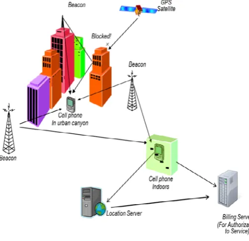
[image:3.595.40.291.516.758.2]The MBS Network have components of a network of highly synchronized beacons which broadcast radio signals in the M-LMS bandwidth. A high level architecture of the system is shown in Figure 1
Figure 1
MBS beacons are used in a wide metro area (intra beacon distance of ~8 to 10Kms) to hotspot the area with the help of licensed wireless spectrum in the M-LMS band. The beacons are self-synchronous and should be installed under open view of the sky for convenience of the coarse synchronization using GPS satellites. Note that typically GPS timing receivers have a jitter in their 1PPS signal to around 25ns RMS. But (timing smoothing) algorithm reduces this deviation to +/- 5ns. Various components in Figure 1 are described :
• Beacon: The beacons in this figure represent the
MBS beacons which broadcast the MBS signal in the M-LMS band. These beacons can be housed on roof tops or towers (which are typically pre-existing cell/broadcast sites). Generally the intra-beacon distance in sub-urban surroundings is around 8-10 Km. Such beacons may also be installed on top of light poles, in future deployments.
• Cell Phone: Its an example device that needs your
current location information is shown as a cell phone under GPS deprived conditions which is like urban layout and indoors areas where GNSS signals from satellites above may not be received easily or it may be the poor performance. The cell phones shown in the figure would be capable of receiving and processing MBS signals. Note that any device equipped to process MBS signals would work under these scenarios. A data or a voice connection is NOT necessary for a device to compute its location using the MBS technology.
• Location Server: In some of the applications, it
can be more precise and useful for a centralized server to calculate the location with information it receives from the mobile because of the additional information that may or may not be available to the mobile device at the time of location tracking..
• Billing Server: A billing server is regulated by
MBS service provider, to monetize access to the MBS beacons by various entities. The billing server may be used at the time of provisioning a device or an application and thus control access to the MBS system based on contractual requirements between MBS service provider or its partners/customers.
• GPS Satellite: Is shown for illustration purpose
that it is blocked by buildings (and severely so in Urban canyons).
2) No Bit For Encryption: For the second problem
B. PROBLEM DESIGN
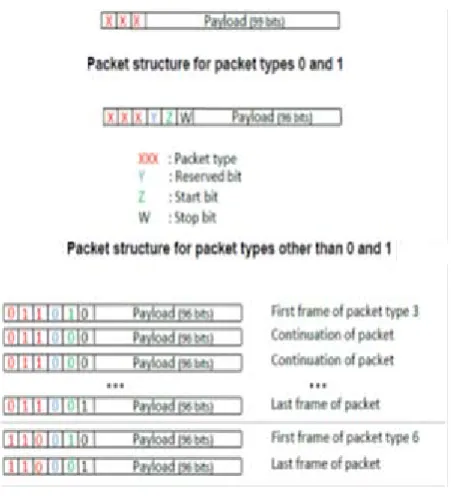
Overall Packet Structure:As there is more than one data packet type, we need an indicator to denote which one the Rx is observing at any given time.
There are only 3 basic packet types, so 3 bits are sufficient enough to describe the packet type. In future replications of MBS, extension packet types will be supported by using ‘111’ as the base packet type (to denote ‘more packet type data to come’), and later have a few bits after that to denote more packet types.
The gross payload of the RH1H2 scheme is 102 information bits per RH1H2 triplet. Out of these 102 bits, 3 will be for packet type index, leaving 99 bits for the data payload and any for any other framing overhead.
If some data to be transmitted is more than that can be carried in one RH1H2 packet (e.g. the session key which will be used later in encryption), the Transmitter will transmit the data over more than one packet. In that case, there is a need for a way to identify how the bits of the current data packet fits into the overall set of the data bits that are to be transmitted. So that we have unambiguous understanding by the receiver on what is being transmitted in each data packet the following scheme is used
In each packet of 102 bits, the first 3 bits are the packet type For packet types 0 and 1:
The next 99 bits deals with the main packet payload For packet types other than 0 and 1:
The 4th bit serves as a reserved bit.
The 5th bit is the start bit, and denotes whether this frame begins as a new packet (1) or its just the continuation of a previous packet (0).
[image:4.595.41.267.498.746.2]The 6th bit is the stop bit, and states whether this is the last frame of a packet (1) or a continuation frame of a packet (0). Summary: 3 bits for framing overhead of packet types 0 and 1, and 6 bits of framing overhead for packet types other than 0 and 1.
Figure 2
V. IMPLEMENTATION
Firstly Created the initial version. Then Fixed minor typographical errors. Made Some changes for additional packet support, PRN list updated & clarifications based on review feedback Later Fixed minor typographical errors Changed the packet structure for conditional access with number of packet IDs reduced to a maximum of 8. This allows packet type 2 to have payload sizes suitable for efficient encryption.
List of changes:
Finished changing no. of bits for packet type to 3 (max num packet IDs of 8),
• Decreased the num bits for temperature to 7 bits (from 9)
• Increased Transmission quality bits to 6 bits (from 3 bits)
• Added the Transmission quality flag meanings
• Also Added UTC time offset from GPS to packet type 2
• Reduced Transmission quality bits from 6 to 4, and decreased altitude bits from 18 to 17, to make room for the added weather data
• Changed weather data which is being transmitted in packet types 0, 1, and 2.Also added humidity and a weather board quality indicator. changed the range, resolution and number of bits needed for pressure and temperature, based on latest study.
Moved the “Dense Urban indicator” in the Transmission quality flags, from having a bit of its own to being one of the flags supported in bits 0-2
Encryption Bit and packet structure
Overall Packet Structure: The basic structure of the packet is same as discussed above in the paper. But as we assigned an encryption bit for security reasons a new dimension of security is given packet data.
•In every packet of 102 bits, the first .3 bits are the packet type
These first 3 bits are always unencrypted.
•For packet types 0 and 1 (the trilateration info packet types) :
The later 99 bits contain the main payload of packet.
For packet type 0, the last 96 bits of the payload are encrypted (bits 4 to 99). For packet type 1, the payload is unencrypted
•For packet types other than 0 and 1:
The 4th bit is the encryption bit, and states whether this packet is encrypted or not. This bit is unencrypted.
The 5th bit is the start bit, and states whether this begins a new packet (1) or the continuation of a previous packet (0). This bit is unencrypted.
The 6th bit is the stop bit, and denotes whether this is the last packet (1) or not (0). This bit is unencrypted.
The next 96 bits contain the main packet payload
The main packet payload is encrypted if the encryption bit is 1, and is unencrypted if the encryption bit is 0.The payload may optionally contain the index of the current packet and/or the total number of packets to be expected with the current information being sent.
Payload is encrypted, therefore, it has to be decrypted in order for the Rx to access the information bits. The steps outlined below assume info bits = decrypt(payload) at the Rx, and payload = encrypt(info bits) at the Transmission. Note that the encrypt function may actually encrypt a portion of the information bits (for example, the first 96 bits of the payload) for encryption efficiency reasons and leave the rest un-encrypted. The decrypt function will do the opposite of the encryption function. The encryption and decryption functions will be defined in future versions of this document.
VI. ANALYSIS
Public safety desires reliable and consistence caller location information to a specific dispatch able building and floor in a multistory environments. Lacking the specific building and floor the wish is for the smallest search ring.
Tighter performance which is less than the 50 m accuracy is required, particularly in urban and dense environments to narrow the search ring to a single building or a more reasonable number of adjacent buildings.
Public safety expects that standardization, commercial availability and deployment of such emerging technologies are priorities for all stakeholders.
Figure 4
• GPS‐like approach for user device integration
• Cellular‐like approach for • urban signal penetration
• Comparison of MBS & AGPS System
Figure 5
VII. CONCLUSIONS
VIII. REFERENCES
[1] Xiaoming Xiao, Albert Kai-sun Wong, Kam Tim Woo, Roger Shu-Kwan Cheng, "An Energy-Efficient Elderly Tracking Algorithm", Communications (ICC) 2011 IEEE International Conference on, pp. 1-5, 2011, ISSN 1550-3607.
[2]A.K. Wong,T.K. Woo,A.T.-L.Lee,X. Xiao,V.W.-H.Luk, K.W.Cheng,1398“An AGPS-based elderly tracking system”,IEEE International1399 Conference on Ubiquitous and Future Networks, 2009 978-1-4244-5637-6/10/©2010 IEEE
[3]P. Daly, "Navstar GPS and GLONASS: global satellite navigation systems," in Electronics & Communication Engineering Journal, vol. 5, no. 6, pp. 349-357, Dec. 1993. doi: 10.1049/ecej:19930069
[4]Paul Riegler, FBT."FCC Bars Light Squared Broadband
Network Plan"
(http://www.frequentbusinesstraveler.com/2012/02/fcc-bars-lightsquaredbroadband-network-plan/). February 14, 2012. Retrieved February 14, 2012
[5] "NAVSTAR GPS User Equipment Introduction"(http://www.navcen.uscg.gov/pubs/gps/gpsuser/gpsus
er.pdf) (PDF). Section 1.2.2http://www.navcen.uscg.gov/pubs/gps/gpsuser/gpsuser.pdf)
(PDF). Section 1.2.2
[6]http://www.navcen.uscg.gov/?pageName=currentNanus&forma t=txt
[7]"Notice Advisory to Navstar Users (NANU) 2012034"(https://gps.afspc.af.mil/gps/archive/2012/nanus/2012034 .nnu). GPS OperationsCenter. May 30, 2012. Retrieved July 2, 2012.