A Method for Matching Parasitic Unidirectional Electrically
Small Array
Ruiyang Li1, *, Gao Wei1, and Derek McNamara2
Abstract—General design guidelines for unidirectional electrically small parasitic array has been proposed by several researchers; however, the input resistance of these antennas is normally very low. In order to practically “convert” this high directivity into realized gain, an appropriate matching mechanism is necessary. This paper gives a simple matching method by adding an inductive stub close to the antenna feed, which can effectively increase the antenna input impedance to 50 Ω and keep the gain almost invariant. Besides, it could make the resonant frequency very close to the frequency where maximum gain occurs, thus a high realized gain can be achieved. Computed and measured examples are given to validate this method.
1. INTRODUCTION
A lot of efforts have been put in miniaturizing antenna size and increasing the directivity, such as designing uni-directional electrically small antenna (ESA). If k denotes the free-space wavenumber and a the smallest sphere enclosing the antenna, ESA is the one with ka < 1. The difficulties for designing uni-directional ESAs are: increasing the directivity without losing much radiation efficiency, which means an increased gain, and figuring out practical feeding mechanisms to “convert” the gain into realized gain. According to IEEE standard of antenna terms [1], “gain” is defined as “directivity multiplied by radiation efficiency”, and “realized gain” is “gain reduced by impedance mismatch”.
Researchers have found various ingenious methods to design uni-directional or super-directive ESAs [2–4] within which a general design guideline was proposed by Yaghjian et al. [4], using two self-resonant ESAs to form a singly fed parasitic array. They also indicated that in order to get this array well matched to a 50-Ω feed line, the single element should be carefully designed (such as using bent and folded wires) to make it have a relatively high radiation resistance (Rrad,elem). Thus the difficulty turns into how to increaseRrad,elem within a very small volume.
The matching problem was also found in [5], where the present authors proposed a method using characteristic modes to optimize unidirectional ESAs. The optimized antennas act just as parasitic arrays. They are close to resonance due to a combination of positive and negative eigenvalues; however, their input resistances are always with a very low value (few ohms). One can hardly control the input resistance during the optimization process, which is only related to eigenvalues and thus feed-free.
In [6] and [7], Best and Altshuler found that, by placing an inductive stub near the feed location of a self-resonant ESA and feed the stub, the originally very low input resistance can be effectively increased to around 50 Ω. However, they did not consider the antenna pattern because it remains omnidirectional within the operating bandwidth [8], with a directivity always around 1.5 (1.77 dBi). In our unidirectional antenna case, gain normally varies significantly within a narrow bandwidth, thus two things must be taken into account: (1) To get it well matched to a 50-Ω feed line. (2) To obtain a high
Received 17 April 2017, Accepted 29 May 2018, Scheduled 7 June 2018 * Corresponding author: Ruiyang Li ([email protected]).
1 School of Electronics and Information, Northwestern Polytechnical University, Xi’an, Shaanxi 710072, P. R. China. 2 School of
122 Li, Wei, and McNamara
realized gain. That is to say, the frequency where the impedance is matched should be very close to the frequency where the antenna reaches its highest gain.
This paper will give numerical and experimental verifications that by placing an inductive stub near the feed of a unidirectional parasitic array, this array can be well matched to a 50-Ω coaxial cable and achieve a maximum realized gain very close to the maximum gain of the original antenna. In this way, the difficulty of first increasing Rrad,elem [4] can be circumvented. One can also use the characteristic mode based optimization method [5] and matching technique to practically realize a unidirectional electrically small antenna.
2. TWO-ELEMENT PARASITIC ARRAY AND MATCHING
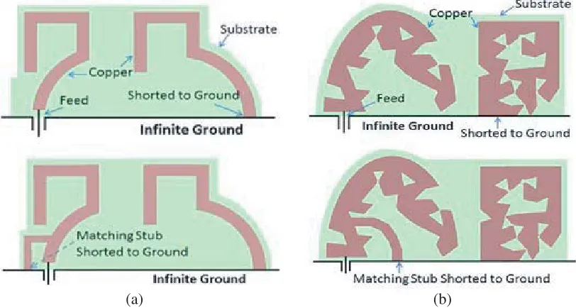
Two parasitic unidirectional arrays and their corresponding stub-matched configurations are given in Fig. 1. Antenna ain Fig. 1(a) is the one measured in [9], wherein we designed a balun for impedance match. It has been discussed that the balun introduced additional loss and a fair amount of occupied volume [9], which is counterproductive to gain enhancement and antenna miniaturization. Antenna b in Fig. 1(b) is one of the optimized antennas in [5].
(a) (b)
Figure 1. Uni-directional antennas and their stub-matched configurations. (a) “Antennaa”, original (above) and matched (below). (b) “Antennab”, original (above) and matched (below).
Considering the structure symmetry, we can feed them using a coaxial cable by placing half of the antenna on an infinitely large ground plane, just as the way of feeding a monopole. In this configuration, input impedance will be decreased by half, and the directivity/gain/realized gain will be increased by 3 dBi. The parasitic element and matching stub are shorted to the ground as indicated in Fig. 1. They are simulated in HFSS, with the antenna conductor defined as copper with a thickness of 35µm and printed on Rogers RT/duroid 5880 substrates with a thickness of 0.508 mm.
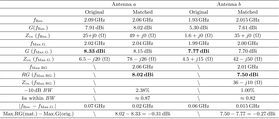
Table 1 and Fig. 2 compare the calculated performance of the original and matched antennas.
fRes,fMax.G andfMax.RG.in Table 1 respectively represent the frequency at which the antenna obtains
its self-resonance, maximum gain and maximum realized gain. Gain (G), realized gain (RG), input impedance (Zin), impedance fractional bandwidth (BW) and electrical size (ka) are given in Table 1. Realized gain of the original antenna is not given in Fig. 2 or Table 1, since the antenna cannot be well matched to a practical 50-Ω coaxial cable.
Our aim is to adjust the shape and position of the stub, to make Zin(fRes.) close to 50 Ω, and
(a) (b)
Figure 2. Simulated directivity and gain of the original and matched antennas in Fig. 1. Realized gain is only given for the matched antenna.
Table 1. Simulated performance of the original and the stub-matched antennas in Fig. 1.
Antennaa Antennab
Original Matched Original Matched
fRes. 2.09 GHz 2.06 GHz 1.93 GHz 2.015 GHz
G(fRes.) 7.91 dBi 8.02 dBi 5.30 dBi 7.61 dBi
Zin (fRes.) 25+j0 (Ω) 49 +j0 (Ω) 1.6 +j0 (Ω) 35 +j0 (Ω)
fMax.G. 2.02 GHz 2.04 GHz 1.99 GHz 2.00 GHz
G(fMax.G.) 8.33 dBi 8.15 dBi 7.77 dBi 7.70 dBi
Zin(fMax.G.) 6.5−j20 (Ω) 78−j26 (Ω) 4.5 +j15 (Ω) 42−j50 (Ω)
fMax.RG \ 2.06 GHz \ 2.01 GHz
RG(fMax.RG.) \ 8.02 dBi \ 7.50 dBi
Zin(fMax.RG.) \ \ 36−j10 (Ω)
−10 dBBW \ 2.38% \ 1.00%
ka withinBW \ ≈0.87 \ ≈0.82
|fRes.−fMax.G.| 0.07 GHz 0.02 GHz 0.06 GHz 0.015 GHz
Max.RG(mat.)−Max.G(orig.) \ 8.02−8.33 =−0.31 dBi \ 7.50−7.77 =−0.27 dBi
It can be directly seen from Fig. 2 that the directivity and gain of the original and matched antennas are almost invariant in spite of a small amount of frequency shift. From Table 1, a number of things can be found:
(1) The originally (very) low input resistance (real part of Zin) can be greatly increased to approximately 50 Ω after adding the matching stub.
(2) Maximum gain is almost invariant after the stub is added.
(3) AlthoughfRes.andfMax.G of the stub-matched antenna are still not exactly the same, they become much closer than the original.
(4) The fractional bandwidth (BW) (matched) is narrow. This is an intrinsic property for unidirectional ESAs if no non-Foster components are added.
124 Li, Wei, and McNamara
much, making the gain remain almost the same as the original. Meanwhile, the stub offers another main current path instead of the extensive current existing only at the feed point of the original antenna, thus a higher input resistance is achieved. Besides, the gap betweenfMax.Gand fRes of the original antenna is wide, considering the antenna’s narrow impedance bandwidth, but the stub can provide additional parasitic reactance, making fMax.G and fRes of the stub-matched antenna move close to each other.
The difference between the maximum realized gain (Max.RG) of the stub-matched antenna and the maximum gain (Max.G) of the original antenna is very small, as shown in Table 1. It means that adding a stub is an effective way to “convert” the gain of the original antenna to a practical realized gain.
We have done simulated experiments for other unidirectional parasitic arrays, and they all give fairly good results as above. Some rules of thumb could be given for obtaining a better performance:
1.) The line width of the matching stub should be comparable in size to that of the antenna. Otherwise, for example, the narrower stub (dashed contour) in Fig. 3(a) will result in a rapidly changing input resistance which is not good for impedance bandwidth.
2.) The matching stub should be placed just close to the feed in order to offer an effective current path to reduce the current at the feed. Otherwise, if the stub is placed as the dashed contour in Fig. 3(b), the antenna input impedance will not change much for matching purposes, and the gain will be greatly decreased.
3.) Placing the matching stub toward outside (like Fig. 1(a)) or inside (like Fig. 1(b)) depends on the antenna itself. One has to try in both ways to find the most appropriate placement. For example, for Antennaa, if the stub is placed toward inside, as the dashed contour shown in Fig. 3(c), the stub-and-antenna mutual coupling introduced is too strong to get it well matched.
(a) (b) (c)
Figure 3. Different matching stub arrangements using the dashed contour (parasitic elements are not shown).
3. ANTENNA MEASUREMENT
Antennas are fabricated and shown in the insets of Fig. 5. Different from the simulation where the ground (GND) plane is infinitely large, they are measured on a twelve-sized conducting polygon with a diameter of 3λat 2 GHz. This polygon is sufficiently large for the input impedance within the bandwidth, and the gain at the peak of the main beam is almost invariant compared with that in the case of an infinite GND, albeit the main beam is tilted up about 30◦ as shown in Fig. 4(a). We measure the antenna realized gain as shown in Fig. 4(b), making the main beam just towards the receiving antenna. Measured reflection coefficient magnitude|S11|and measured realized gain over frequency for the two stub-matched antennas are plotted in Fig. 5. Simulated |S11|, directivity, gain and realized gain of the stub-matched antennas placed on infinitely large GND are also given to show the fairly good practical antenna performance.
To restate our observation from Table 1, it can be seen now from Fig. 5 that fRes., where |S11| reaches its lowest value, is very close to fMax.G. for both antennas. Besides, the measured maximum
(a) (b)
Figure 4. Antenna measurement using a twelve-sided polygon ground. (a) Main beam tilted angle. (b) Antenna realized gain measurement in anechoic chamber.
(a) (b)
Figure 5. Comparison of measured and simulated parameters. (a) Antennaa. (b) Antennab.
simulated maximum gains, which are 8.33 dBi for Antenna a and 7.77 dBi for Antenna b. These facts indicate that the stub-matching technique is valid to practically realize a unidirectional electrically small antenna.
4. CONCLUSION
Putting an inductive stub close to the feed point of a parasitic unidirectional array has been verified to be an effective way for matching the array to a 50-Ω coaxial cable. This matched array can achieve a realized gain whose maximum value is very close to the maximum gain of the original antenna.
Although we did not examine this method for all the unidirectional ESAs appeared in the literature, the already done experiments and fairly good results would be positive indications to consider it for matching antennas of the similar type.
REFERENCES
1. IEEE STD 145-2013, Standard for Definitions of Terms for Antennas, 2013.
126 Li, Wei, and McNamara
3. Haskou, A., A. Sharaiha, and S. Collardey, “Design of small parasitic loaded superdirective end-fire antenna arrays,” IEEE Transactions on Antennas and Propagation, Vol. 63, No. 12, 5456–5464, 2015.
4. Yaghjian, A. D., T. H. O’Donnell, E. E. Altshuler, and S. R. Best, “Electrically small supergain end-fire arrays,” Radio Sci., Vol. 43, No. 3, 2008.
5. Li, R., D. McNamara, G. Wei, and J. Li, “Increasing radiation efficiency using antenna shape optimization approach,” IEEE Antennas and Wireless Propagation Letters, Vol. 17, No. 3, 393– 396, 2018.
6. Best, S. R., “A discussion on the quality factor of impedance matched electrically small wire antennas,”IEEE Transactions on Antennas and Propagation, Vol. 53, No. 1 II, 502–508, 2005. 7. Altshuler, E. E., “A method for matching an antenna having a small radiation resistance to a
50-ohm coaxial line,”IEEE Transactions on Antennas and Propagation, Vol. 53, No. 9, 3086–3089, 2005.
8. Yaghjian, A. D., M. Gustafsson, and L. Jonsson, “Minimum Q for lossy and lossless electrically small dipole antennas,” Progress In Electromagnetics Research, Vol. 143, 641–673, 2013.