Radiation Field and Optical Coupling Evaluation Using a New
Mathematical Model
Mansour Bacha1, 2, * and Abderrahmane Belghoraf1
Abstract—The mathematical model elaborated in this paper is based on the concept of intrinsic modes in order to analyze and synthesize optical wave propagation along a non-uniform optical structure which is used in integrated optics communication as tapered optical coupler. The new mathematical model is simply developed by introducing modifications to the intrinsic integral, and its numerical evaluation illustrates the electromagnetic field distribution inside a taper thin film and also outside the waveguide constituted by the substrate and the cladding of lower refractive index. The proposed method permits efficiently tracking the behaviour of the optical waves both inside and outside the optical waveguide, and quantifying the radiation and optical coupling occurring from the taper thin film of higher refractive index to adjacent mediums until a total energy transfer; this happens at thicknesses lower than waveguide cutoff thickness of each mode. The new model can be applied to all types of tapered optical coupler, made from different optical materials and having different wedge angles.
1. INTRODUCTION
Integrated optics, which allows the miniaturization of optical devices, has grown considerably in recent decades and takes advantage of the relatively short wavelength of the light in this range, which permits the fabrication of miniature components [1]. Typical dimensions for the optical waveguide are in the order of a micrometer and the energy in these waveguides can be coupled to the adjacent mediums [1– 3]. The technology required to fabricate planar lightwave circuit components of such dimensions is therefore common in the well-established micro-electronic technology, using the tools and techniques of the semiconductor industry [1].
Though there exist several types of optical couplers [2–9], such as prism couplers, grating couplers and directional couplers, the tapered optical coupler is characterized by its simplicity and compatibility with planar technology circuits.
In order to analyze and synthesize the propagation, radiation and optical coupling occurring in a tapered optical coupler, a new mathematical model based on the concept of intrinsic modes will be proposed. The new model uses a spectral integral for assessing the behaviour of the optical waves within the non-uniform thin film of greater refractive index, as well as in the substrate and the cladding of lower refractive indexes.
The concept of intrinsic modes was first developed for the acoustic underwater applications [10, 11], and for its importance and compatibility with the optical structure, it has been applied in integrated optics for the non-uniform structure [12–17]. Intrinsic modes are solutions of Maxwell’s equations satisfying the boundaries conditions at the interfaces of the optical waveguide.
One note that, for the evaluation of the optical propagation in optical waveguides, many analytical and numerical methods have been applied, such as the beam propagation method (BPM), finite
Received 25 July 2016, Accepted 11 October 2016, Scheduled 4 November 2016
* Corresponding author: Mansour Bacha ([email protected]).
difference beam propagation method (FDBPM) and effective index method [18–22], the advantages of the new method, introduced in this paper, are its simplicity and universality.
For the goal to make the intrinsic modes method applicable to all types of non-uniform waveguides in integrated optics and thereby be able to determine the electromagnetic field distribution in all media constituting the optical waveguide and evaluate the coupling efficiency, some modifications, to the intrinsic integral already established [14, 15, 23], will be introduced.
2. ANALYSIS OF THE STRUCTURE OF TAPERED OPTICAL COUPLER
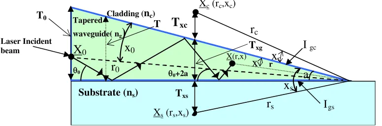
The structure of the non-uniform optical waveguide studied in this paper is illustrated in Figure 1. It consists of a tapered thin film of higher refractive index (ng), sandwiched by a substrate and a cladding of lower refractive indexes respectively (ns) and (nc). The refractive indexes values are defined as:
ng > ns> nc. The thickness ‘T’ of non-uniform waveguide decreases linearly from the left to the right (see Figure 1); the light is guided in the mediumngby successive reflections on the waveguide interfaces
Igc (between the mediumsng and nc) andIgs (between the mediums ng and ns).
The rays reach an observation point ‘X’ after undergoing several reflections on interfaces Igc and
Igs [3, 14, 15]. Each pair of reflections on waveguide interfaces increases the angle of incidence ‘θ’ on Igs, by twice the wedge angle ‘a’, angle formed by the interfacesIgcandIgs. Aftermpairs of reflections, the
new angle of incidence will become (θ+ 2ma) [3, 14, 15]. Consequently, at a certain point, the angle of incidence will become larger than the critical angle θc, and the energy will thus start to be radiated to
the adjacent mediumsnc andns. After cutoff, the optical energy is coupled from the non-uniform thin
layer to adjacent mediums; for this reason, the tapered optical waveguide is considered as an optical coupler, in addition to its guiding property [3, 23–26].
In order to analyze the propagation process of the light, one will track all optical rays reflected by the waveguide interfaces; from an incident ray positioned at X0 to an observation point X, each ray can be characterized by the number of times it hits the Igc and Igs interfaces. Four kinds of rays will be defined, and discrete number of rays reaches the observation point X:
Rays that go first towards the interfaceIgc and will have even or odd reflections at interfaces Igc
and Igs will be defined respectivelyWe+(X0, X) andWo+(X0, X).
Rays that go first towards the interface Igs and will have even or odd reflections at interfacesIgc
andIgs will be defined respectivelyWe−(X0, X) andWo−(X0, X). The four kinds of rays are introduced and demonstrated in [14, 15, 23].
In previous works applying the intrinsic method to the tapered waveguide [3, 13–15], the phase of Fresnel coefficient at the interfaceIgc was posed equal to π, because they have considered the presence
of total and perfect reflection at this interface, and this supposition will not permit evaluation of the electromagnetic field in the cladding medium nc, and the quantification of the radiation field and the
optical coupling will not be really exact. For these reasons, in our study, we will treat the general case, using the exact phase of Fresnell coefficient depending on refracted indexes of each medium (ng etnc). Some papers [12, 16, 17] use the exact Fresnel coefficient to determine the intrinsic integral, but they follow a different approach from those used by [3, 14, 15, 23].
The phases of the Fresnel coefficients introduced at Igc and Igs interfaces, given below, use a complementary angle of that given in [2] at each interface for Transverse Electric (TE) mode:
φ+(θ+) = 2 arctan
n2
g·cos2(θ+)−n2c
n2
g−n2g·cos2(θ+)
(1)
φ− (θ−) = 2 arctan
n2
g·cos2(θ−)−n2s
n2
g−n2g·cos2(θ−)
(2)
The cumulative phases Φ+e, Φ+o, Φ−e and Φ−o [14, 15] of waves after even or odd reflections on Igc and
Igs interfaces are:
Φ+e(θ0, θn) =
n
m=1
2 arctan
n2
g·cos2(θm+)−n2
c
n2
g−n2g·cos2(θm+)
+
n
m=1
2 arctan
n2
g·cos2(θ−m)−n2
s
n2
g−n2g·cos2(θ−m)
Xc(rc,xc)
Laser Incident beam
Cladding (nc)
x
c 0+2a θ0r
cr
0x
0a
Taperedwaveguide( ng
)
Substrate (ns)
Txg T0
T
xcXs(rs,xs)
r
sx
sTxs
X
0 X(r,x)x
rIgs Igc T
θ
Figure 1. Optical ray from the pointX0(x0, r0) to an observation pointX(x, r) after many reflections.
Xc(rc, xc) and Xs(rs, xs) represent positions points in the cladding and substrate respectively at thicknessTxc andTxs. Txg represents the tapered waveguide thickness.
Φ+o(θ0, θn) = Φ+e(θ0, θn)−2 arctan
n2
g·cos2(θn−)−n2
s
n2
g−n2g·cos2(θn−)
(4)
Φ−e(θ0, θn) =
n m=1 2 arctan n2
g·cos2(θ−m)−n2
s
n2
g−n2g·cos2(θ−m) + n m=1 2 arctan n2
g·cos2(θm+)−n2
c
n2
g−n2g·cos2(θm+)
(5)
Φ−o(θ0, θn) = Φ−e(θ0, θn)−2 arctan
n2
g·cos2(θn+)−n2
c
n2
g−n2g·cos2(θn+)
(6)
θ+m− are the incident angles at themth reflection respectively on Igc and Igs interfaces.
θ+n− are the maximum incident angles respectively onIgc andIgs interfaces from X0 to X. In Eqs. (3)–(6), incident anglesθm+,θm− are the angles difference after each reflection on Igc andIgs
interfaces:
θm+−θ−m=a (7)
At the mth reflections and on the same interface, the incident angle will be:
θ+m−=θ0+−+ 2·a·(m−1) (8) After applying the Euler Maclaurin formula [15, 27] to Eqs. (3)–(6), and replacing the incident angleθn
by θ, we will obtain the expressions of the four kinds of rays for the TE mode as follows:
We+(X0, X) = exp
j·(Φ+e(θ0, θ) +k·R+e(θ0, θ))
= exp ⎡ ⎣j·
⎛ ⎝1
2φ +(
θ0) + 1 2φ
+(
θ) + 1 2·a
θ
θ0
φ+(θ)·dθ+1 2φ
−(θ 0) +
1 2φ
−(θ)
+ 1 2·a
θ
θ0
φ−(θ)·dθ+Ee+(θ, φ+(θ)) +Ee+(θ, φ−(θ)
⎞ ⎠
+k·r0·cos(θ0−a−x0)−k·r·cos(θ+a−x)) ] (9)
Wo+(X0, X) = exp
j·(Φ+o(θ0, θ) +k·R+o(θ0, θ))
= exp ⎡ ⎣j·
⎛ ⎝1
2φ +(θ
0) + 1 2φ
+(θ) + 1 2·a
θ
θ0
φ+(θ)·dθ+1 2φ
−(θ 0)−
1 2φ
+ 1 2·a
θ
θ0
φ−(θ)·dθ+Ee+(θ, φ+(θ)) +Ee+(θ, φ−(θ))
+k·r0·cos(θ0−a−x0)−k·r·cos(θ−a+x)) ] (10)
We−(X0, X) = exp
j·(Φ−e(θ0, θ) +k·R−e(θ0, θ))
= exp ⎡ ⎣j·
⎛ ⎝1
2φ
−(θ 0) +
1 2φ
−(θ) + 1
2·a
θ
θ0
φ−(θ)·dθ+1 2φ
+(
θ0) + 1 2φ
+(
θ)
+ 1 2·a
θ
θ0
φ+(θ)·dθ+Ee−(θ, φ−(θ)) +Ee−(θ, φ+(θ))
+k·r0·cos(θ0−a+x0)−k·r·cos(θ−a+x) )] (11)
Wo−(X0, X) = exp
j·(Φ−o(θ0, θ) +k·R−o(θ0, θ))
= exp ⎡ ⎣j·
⎛ ⎝1
2φ
−(θ 0) +
1 2φ
−(θ) + 1
2·a
θ
θ0
φ−(θ)·dθ+1 2φ
+(
θ0)− 1 2φ
+(
θ)
+ 1 2·a
θ
θ0
φ+(θ)·dθ+Ee−(θ, φ−(θ)) +Ee−(θ, φ+(θ))
+k·r0·cos(θ0−a+x0)−k·r·cos(θ+a−x) )] (12)
In Eqs. (9)–(12), R+e(θ0, θ), R+o(θ0, θ), R−e(θ0, θ) and R−o(θ0, θ) are geometrical lengths, and
Ee+(θ, φ+(θ)), E+e(θ, φ−(θ)), Ee−(θ, φ+(θ)) and Ee−(θ, φ−(θ)) are the errors introduced by Euler
Maclaurin formula [27] for the Eqs. (3)–(6).
The contribution of all species of plane waves incidents on the two interfacesIgsandIgcis as [14, 15]:
W(θ0, θ) =
n
m=1
We+(θ0, θ) +Wo+(θ0, θ) +We−(θ0, θ) +Wo−(θ0, θ)
(13)
Modifications which have been introduced to the mathematical model of intrinsic integral, as it was done previously, will allow obtaining a greater accuracy in the evaluation of the optical propagation and radiation, occurring in the waveguide, as will be shown in the next section.
3. DETERMINATION OF THE NEW EXPRESSION OF THE MODIFIED INTRINSIC INTEGRAL
The new expression of the modified intrinsic integral is obtained by first applying the Poisson transformation [14, 15, 23, 27] to Eq. (13);
W(θ0, θ) =
c
1 2a
+∞
q=−∞
We+(θ0, θ)+Wo+(θ0, θ)+We−(θ0, θ)+Wo−(θ0, θ)
·exp(−j·2π·q·m)dθ (14)
Eq. (14), represents an approximation of a spectrum of all incident waves inside the optical waveguide whereq represents the mode number of the propagation wave, andm is deduced from Eq. (8).
After transformations, Eq. (14) becomes:
W(θ0, θ) = 1 2a
C
The previous analysis demonstrates the existence of four kinds of waves (see Eqs. (9)–(15)), but the four waves are interrelated [15] because a wave, which moves first to the higher interfaceW+, once reflected can be classified as a wave that goes to the lower interfaceW−, and the same remark can be applied to a wave that goes to the lower interfaceW−, once reflected, it becomes W+.
One notices that the mathematical model introduced in this paper is difficult to use. To evaluate the modified intrinsic integral, we will consider a fixed position of the light-emitting source and a variable position of the observation point; that is to say, source parameters which are constants will have stationary influence in the phase of the modified intrinsic integral during the propagation of optical waves. For any observation point inside the waveguide as X(X, θ), we define the modified intrinsic integral as:
W(X, θ) = 1 2a
C
(exp(j·Pe+(X, θ)) + exp(j·Po+(X, θ)) + exp(j·Pe−(X, θ)) + exp(j·Po−(X, θ)))dθ (16)
We have two possibilities to evaluate the modified intrinsic integral according to the remark given after Eq. (15). The first is to consider the waves going first to upper interface Igc, which have even and odd
reflections on waveguide interfaces:
W+(X, θ) = 1 2a
C
(exp(j·Pe+(X, θ)) + exp(j·Po+(X, θ)))dθ (17)
The second possibility is to consider the waves going first to lower interface Igs, which have even and odd reflections on waveguide interfaces:
W−(X, θ) = 1 2a
C
(exp(j·Pe−(X, θ)) + exp(j·Po−(X, θ)))dθ (18)
The field distribution in the substrate and cladding is obtained by using the Fresnel transmission coefficient [11–13] at each interface in the modified intrinsic integral:
Ws,c(X, θ) = 1 2a
C
1 + exp
j·2 arctan
n2
g·cos2(θ)−n2s,c
n2
g−n2g·cos2(θ)
·exp(j·Po+−(X, θ))
dθ (19)
The modified intrinsic integral can be applied to any tapered waveguide in optics or any other electromagnetic applications governed by successive reflections on waveguide interfaces independent of the position of the source, considered as source-free [3, 11, 14–17]. The same analysis used in this work can be perfectly applied to the Transverse Magnetic (TM) mode.
4. RESULT AND COMMENTS
Various methods can be used to assess approximately the spectral integral W+(X, θ) or W−(X, θ): one can name the Fast Fourier Transform (FFT), steepest descent path (SDP) and the numerical method consisting in integrating directly along the real axis of the incident angles θ in the interval (0< θ < π/2) [3, 12–15, 17, 24].
In order to evaluate numerically the radiation field and optical coupling occurring in the tapered waveguide, a new model, introduced in this paper, will be applied to: symmetric SiO2/Polymer/SiO2 (ng = 1.77, ns = nc = 1.45) and asymmetric Air/Polymer/SiO2 (ng = 1.77, ns = 1.45 and nc = 1) waveguides at wavelength λ = 1µm [28], and also to symmetric AlGaAs/GaAs/AlGaAs (ng = 3.44,
ns = nc = 3.36) and asymmetric Air/GaAs/AlGaAs (ng = 3.44, ns = 3.36 and nc = 1) waveguides
(a) (b)
0 1 2 3 4 5 6 7 8 9 10 11
0 1 2 3 4 5 6
C
u
t-o
ff
W
a
ve
gui
de
Thi
c
k
ne
s
s
(μ
m
)
Mode Number q
Cut-off Ticknesses of TM mode Cut-off Ticknesses of TE mode
0 1 2 3 4 5 6 7 8 9 10 11
0 2 4 6 8 10 12
Cut-off Ticknesses of TM mode Cut-off Ticknesses of TE mode
C
u
t-of
f W
a
ve
gui
de
Thi
c
k
ne
s
s
Mode Number q
(μ
m
)
(μ
m
)
(μ
m
)
Figure 2. Comparison of the cut-off thicknesses of non uniform optical waveguide for the modes: 1≤p≤10, of TE mode (points) and TM mode (* points) applying the exact Fresnel coefficient given in Eq. (1). (a) Air/polymer/SiO2 waveguide. (b) Air/AsGa/AlAsGa waveguide.
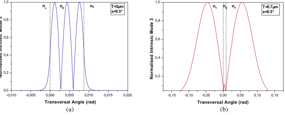
-0,010 -0,005 0,000 0,005 0,010 0,015 0,020
0,0 0,2 0,4 0,6 0,8 1,0
ns
ng
n
c T=3µm
a=0.5°
-0,15 -0,10 -0,05 0,00 0,05 0,10 0,15
0,2 0,4 0,6 0,8 1,0
ns
nc ng T=0.7µm
a=0.5°
Transversal Angle (rad)
Normalised Intrinsic Mode 3
Transversal Angle (rad)
Normalised Intrinsic Mode 3
(a) (b)
Figure 3. Transverse distribution of third intrinsic normalised mode (q = 3) of a symmetric polymer optical waveguide; the wedge angle is: a= 0.5◦. (a) At thicknessT = 3µm, greater than the waveguide cutoff thickness. (b) At thickness T = 0.7µm, lower than the waveguide cut-off thickness.
Figure 2, illustrates the variation of the waveguide cut-off thicknesses of two asymmetric waveguides for ten modes (p) of the TE and TM modes using the dispersion equation given in [2] where the integer
p is defined as p ≥ 0. We note that for all modes (1≤ p ≤10), as shown in Figure 2, the waveguide cutoff thicknesses of TM mode are greater than the TE mode ones.
The simulation results, given in Figures 3 and 4, show a normalised intrinsic field distribution of the third mode (q= 3); this mode was chosen because, in our case, we consider odd modes as giving better views of the symmetries of the field distribution in adjacent mediums. Intrinsic modes are normalized to a maximum value of the third mode for two wedge angles,a= 0.5◦ and a= 5◦, respectively.
-0,10 -0,05 0,00 0,05 0,10 0,15 0,20 0,00
0,05 0,10 0,15 0,20 0,25 0,30 0,35
T=3µm a=5°
ns
nc ng
-0,4 -0,2 0,0 0,2 0,4 0,6 0,8 1,0 0,1
0,2 0,3 0,4 0,5 0,6 0,7 0,8
ns
nc ng T =0.8µm
a=5°
Transversal Angle (rad)
Normalised Intrinsic Mode 3
Transversal Angle (rad)
Normalised Intrinsic Mode 3
(a) (b)
Figure 4. Transverse distribution of third intrinsic normalised mode (q= 3) of an asymmetric polymer optical waveguide; the wedge angle is: a= 5◦. (a) At thickness T = 3µm, greater than the waveguide cut-off thickness. (b) At thickness T = 0.8µm, lower than the waveguide cut-off thickness.
0,5 1,0 1,5 2,0 2,5 3,0
0 10 20 30 40 50 60 70 80 90 100
P
o
w
e
r Dis
trib
u
tion (%
)
Waveguide Thickness (µm)
Power Rate in the substrate (ns)
Power Rate in the cladding (nc)
Power Rate in the guide (ng)
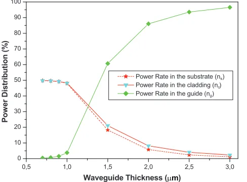
Figure 5. Third mode (q = 3) Power distribution in symmetric non uniform optical waveguide constituted by AlGaAs/GaAs/AlGaAs for the wedge anglea= 1◦.
0,5 1,0 1,5 2,0 2,5
0 20 40 60 80 100
Power Rate in the substrate (ns)
Power Rate in the guide (ng)
P
o
w
e
r Di
s
trib
ution (%
)
Waveguide Thickness (µm)
Figure 6. Third mode (q = 3) Power distribution in asymmetric non uniform optical waveguide constituted by (Air/GaAs/AlGaAs) for the wedge angle a= 10◦.
For asymmetric waveguide (Figure 4), before cutoff thickness, the field is, as for the symmetric waveguide, concentrated in the tapered waveguide, but the evanescent fields distribution are not symmetric in the adjacent mediums (Figure 4(a)). Figure 4(b), illustrates the field distribution after the cutoff thickness. We note that the field is coupled by radiation phenomena, almost entirely to substrate medium (ns); optical coupling to the cladding medium is small compared to the substrate, and it will be insignificant with the decrease of the waveguide thickness.
Figures 5 and 6 show the power distribution of the third mode in different mediums of two tapered couplers, for two wedge angles, respectively a = 1◦ and a= 10◦. Figure 5 depicts the gradual power transfer from tapered waveguide ng to adjacent mediums nc and ns. We note, after the cutoff, that all optical energy is transferred to adjacent mediums. For asymmetric waveguide, illustrated in Figure 6, optical energy is principally transferred to the substrate.
method permits efficiently tracking the behaviour of the optical waves both inside and outside of the optical waveguide and quantifying the radiation and optical coupling occurring in the optical tapered coupler.
The new model of intrinsic integral developed gives a better view of the field distribution in different mediums of the tapered waveguide and permits better evaluation of the optical coupling than old models, as will be shown in the future results.
The new model can be perfectly used to evaluate the optical phenomena of propagation, radiation and optical coupling occurring in all types of non-uniform optical waveguides which can be made from different optical materials and having different wedge angles formed by the waveguide interfaces.
The results obtain by using the new intrinsic model are very close to experimental results [25] as will be demonstrated in future works.
5. CONCLUSION
The new model of intrinsic concept introduced in this paper permits the efficient evaluation of the electromagnetic field distribution in all mediums constituting the tapered optical coupler for different refractive indexes and different wedge angles formed by the waveguide interfaces.
By using the modified intrinsic model, one can efficiently track the power distribution present in the three regions of tapered optical waveguides before and after the waveguides cutoff and can also evaluate the optical coupling occurring in the optical couplers from the tapered thin film to the adjacent mediums by the radiation phenomena
The simulation results show, for thicknesses greater than the waveguide cutoff thickness, the electromagnetic field concentrated in tapered optical waveguide (nc), and when the thicknesses become
lower than the cutoff thickness, the energy is radiated to the substrate and cladding medium (nsandnc).
The new model can be applied to all types of non-uniform tapered optical waveguide, thus modulate the propagation and radiation of the electromagnetic field, and systematically evaluate the optical coupling phenomena occurring in an optical coupler.
ACKNOWLEDGMENT
This work is co-supported by the University of Sciences and Technology of Oran Mohamed Boudiaf (USTOMB) and the Centre of Satellites Development (CDS), Oran, Algeria.
REFERENCES
1. Lifante, G., Integrated Photonics: Fundamentals, John Willey & Sons Ltd., Chichester, England, 2003.
2. Boudrioua, A., Photonic Waveguides Theory and Applications, ISTE Ltd, London, UK, 2009. 3. Bacha, M. and A. Belghoraf, “Evaluation of optical propagation and radiation in optical waveguide
using a numerical method,” Chinese Optics. Letters, Vol. 12, Issue 7, 070801-4, 2014.
4. Luyssaert, B., et al., “Efficient nonadiabatic planar waveguide tapers,” Journal of Lightwave Technology, Vol. 23, No. 8, 2462–2468, 2005.
5. Debnath, K., et al., “Low-loss silicon waveguides and grating couplers fabricated using anisotropic wet etching technique,”Frontiers in Materials, Vol. 3, 1–7, Article 10, 2016.
6. Subbaraman, H., et al., “Recent advances in silicon-based passive and active optical interconnects,”
Optics Express, Vol. 23, No. 3, 2487–2510, 2015.
7. Yoo, K. and J.-H. Lee, “Design of a high-efficiency fiber-to-chip coupler with reflectors,” EIE Transactions on Smart Processing and Computing, Vol. 5, No. 2, 123–128, 2016.
8. Okamoto, K., Fundamentals of Optical Waveguides, Elsevier Inc., Burlington, MA, USA, 2006. 9. Whang, A. J., et al., “Innovative coupler design based on a tapered light pipe with lens,”Chinese
10. Kamel, A. and L. B. Fielsen, “Spectral theory of sound propagatin in an ocean channel with weakly sloping bottom,” J. Acoust. Soc. Am., Vol. 73, No. 4, 1120, 1983.
11. Arnold, J. and A. Ansbro, “Intrinsic modes in wedge shaped oceans,” Journal de Physique Colloques, Vol. 51, No. C2, C2-953–C2-956, 1990.
12. Arnold, J. M., A. Belghoraf, and A. Dendane, “Intrinsic mode theory of tapered optical waveguide,”
IEE Proceedings, Vol. 132, No. 6, 314–318, 1985.
13. Dendane, A. and J. M. Arnold, “Beam radiation from tapered waveguides,” IEEE Journal of Quantum Electrons, Vol. 22, No. 9, 1551–1556, 1986.
14. Belghoraf, A., “A simplified approach to analysing non uniform structure in integrated optics,”
A.M.S.E. Periodicals: Modelling, Measurement and Control. A, Vol. 74, No. 5, 61–71, 2001. 15. Belghoraf, A., “Numerical comparison between intrinsic and adiabatic modes for tapered optical
waveguide in optical communication,”A.M.S.E. Periodicals: Modelling, Measurement and Control. A, Vol. 45, No. 4, 21–42, 1992.
16. Cada, M., et al., “Intrinsic modes in tapered optical waveguides,” IEEE Journal of Quantum Electronics, Vol. 24, No. 5, 1988.
17. Cada, M., et al., “A substantially improved treatment of intrinsic modes in tapered optical waveguides,” IEEE Journal of Quantum Electronics, Vol. 25, No. 5, 1989.
18. Prajzler, V., H. Tuma, J. Spirkova, et al., “Design and modeling of symmetric three branch polymer planar optical power dividers,” Radioengineering, Vol. 22, No. 1, 233–239, 2013.
19. Kawano, K. and T. Kitoh, Introduction to Optical Waveguide Analysis, John Willey & Sons Ltd., New York, USA, 2001.
20. Yip, G. L., “Simulation and design of integrated optical waveguide devices by the BPM,”Integrated Optical Circuits SPIE, Vol. 1583, 240–248, 1991.
21. Han, Y. T., J. U. Shin, D. J. Kim, et al., “A rigorous 2D approximation technique for 3D waveguide structures for BPM calculations,” ETRI Journal, Vol. 25, No. 6, 535–537, 2003.
22. Ismail, M. M. and M. N. Shah Zainuddin, “Numerical method approaches in optical waveguide modelling,” Applied Mechanics and Materials, Vols. 52–54, 2133–2137, 2011.
23. Bacha, M. and A. Belghoraf, “Analysis of electromagnetic Wave propagation along optical waveguide,” Int. Rev. on Mod. and Simul. (I.RE.MO.S), Vol. 6, 1624, 2013.
24. Belghoraf, A. and M. Bacha, “Mathematical model for analysing a tapered optical coupler,”
International Research Journal of Engineering and Technology (IRJET), Vol. 3, No. 5, 3049–3052, 2016.
25. Tien, P. K., G. Smolinsky, and R. J. Martin, “Radiation fields of a tapered film and a novel film-to-fiber coupler,” IEEE Trans. Microwave Theory Tech., Vol. 23, 79–85, 1975.
26. Rumao, T., X. Wang, H. Xiao, et al., “Coherent beam combination of fiber lasers with a strongly confined tapered self-imaging waveguide: Theoretical modelling and simulation,” Photon. Res., Vol. 1, No. 4, 2013.