Differentially-Fed, Multi-Band Dual-Polarized Filtering Patch
Antenna without Extra Circuits
Jianfang Deng1, * and Lanping Feng2
Abstract—In this paper, a multi-band patch antenna with bandpass filtering response is proposed. The antenna consists of two pairs of crossed dipoles, four Γ-shaped feedlines, and four steeped-impedance microstrip lines. With the introduction of Γ-shaped feedlines and U-shaped slots on the radiating patch, extra radiation nulls are induced, and four operation bands with band-pass filtering response are obtained. More importantly, the filtering response of the antenna is generated without any filtering circuits, which is easy to design for antenna engineers. Measured results of the prototype show that the proposed antenna has stable radiation patterns with low cross-polarization level of better than
−26 dBi over the four operation bands. Good filtering response with deep roll-off can also be observed between different operation bands. Excellent radiating performances make it a promising candidate for 5G wireless communication systems.
1. INTRODUCTION
In modern wireless communication systems, antennas play important roles in communication quality. To improve channel capacity, dual-polarized antennas are mostly widely used. Meanwhile, with developments of wireless communication technologies, antennas are largely integrated together as the space resource is compressed further. Then, more challenges are presented, such as suppression of interfere between different antenna systems. To solve this problem, antennas with wide operation band or multiple bands are applied, as the antennas have more choices of frequencies. However, for most antennas, radiation gains outside the working bands are not so well suppressed. Thus, interference between antennas working at different bands still exists, which greatly influences the performances of communication systems. In recent years, antennas with filtering responses have become promising candidates to solve the problem, and most of them introduce filters into antenna feedlines [1–5], which makes it easier for integration with the whole system. Besides, the introduction of filters always contributes to good filtering responses. For example, in [3], a dual-mode stub-loaded resonator is employed to feed the two patch antennas, and a dual-band bandpass filtering response of the realized gain is obtained. In [5], a filtering balun is integrated into the feedline of a dielectric resonator antenna, and good filtering response with steep roll-off can be obtained outside the working band. However, the design of filters seems always difficult for antenna engineers. Thus, it has become a trend to use fewer filters and maintain filtering response at the same time [6–13]. For example, in [6] and [7], two simple filtering stubs are introduced into the feedline, and good filtering responses with tunable radiation nulls are obtained. Similar techniques can also be found in [8–10]. Some other methods have also been applied, which concentrate on the filtering responses of radiators. For example, by etching slots on the radiator, resonant mode of the antenna can be modified, and the non-radiating part contributes to the
Received 12 July 2019, Accepted 13 August 2019, Scheduled 28 August 2019 * Corresponding author: Jianfang Deng ([email protected]).
1 Institute of Railway Technology, Nanjing, Jiangsu 210031, People’s Republic of China. 2 Asiainfo Technology (Nanjing) Co. Ltd,
radiation null [10–12]. Some other approaches, such as changing the electromagnetic characteristics of parasitic elements, have also been proposed [13].
In most designs of filtering antennas, very few of them can be applied in dual-polarized antenna systems with multi-band applications. At the same time, in most multiband antenna designs, filtering responses are not taken into consideration [2, 14, 15]. In view of this, a multi-band filtering antenna with dual-polarized performance is proposed in this paper. The antenna is differentially fed by stepped microstrip lines without extra filtering circuits. With the introduction of a Γ-shaped feeding structure and stepped microstrip lines, as well as four U-shaped slots on the radiating patches, the proposed antenna have four operation bands with deep roll-offs of the realized gain between them. Measured results validate our design method. Stable and unidirectional radiation patterns with low cross-polarization of better than −26 dB are also observed over the four bands, which make it a promising candidate for 5G wireless communication systems.
2. DESIGN OF THE MULTI-BAND FILTERING ANTENNA
Figure 1 illustrates the geometry of the proposed antenna. Layer 1 and layer 2 are F4B substrates with permittivity of 2.65 and loss tangent of 0.002. The cross-dipoles are printed on the top layer of layer 1. Part of the Γ-shaped feeding structure is printed on the top layer of layer 1 to excite the radiating
(a) (b)
(c) (d)
patch. The metal post is connected to the microstrip feedline printed on the bottom layer of layer 2. The metal ground is printed on the top layer of layer 2. When port 1 and port 2 are differentially fed, a vertical polarization is obtained. Similarly, when port 3 and port 4 are differentially fed, a horizontal polarization is obtained. As the structure of the proposed antenna is symmetric, the two polarizations have same active VSWR and radiation patterns. Thus only the radiation performance of the horizontal polarization is discussed.
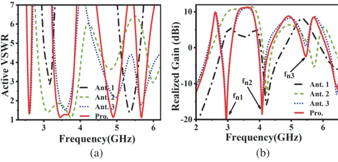
To get a deep insight into the operating principle of the proposed antenna, an evolution of the antenna is shown in Fig. 2. Ant. 1 is two pairs of cross-dipoles differentially fed by coaxial probes. Ant. 2 is two pairs of cross-dipoles differentially fed by a Γ-shaped feeding structure and microstrip lines. Ant. 3 is U-shaped slots etching on Ant. 2. The simulated active VSWR and realized gain are shown in Fig. 3. it can be seen that Ant. 1 has two operation bands, and a radiation null with deep roll-off is observed at about 4.22 GHz (fn2). To better demonstrate this radiation null, current distribution
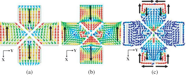
on the patch at 4.22 GHz is illustrated in Fig. 4(a). It can be seen clearly that the currents on the patch are very week (the max current intensity is 5 A/m), and the dominant currents on the driven patches along x-axis and the parasitic crossed dipoles along y-axis are out of phase, which leads to a cancellation. Thus, the radiation null is obtained. With the Γ-shaped feeding structure added (Ant. 2), another resonant mode occurs at 3.12 GHz. Besides, the resonant mode at high frequency band moves to lower band (at 4.82 GHz), and another resonant mode occurs at a higher band (at 6.0 GHz), as well as a radiation null at 5.72 GHz (fn3). The current distribution on the patch at 5.72 GHz is illustrated
in Fig. 4(b). It can be seen that the dominant currents on the two pairs of crossed dipoles are in the opposite directions, which leads to a radiation null in far field. Thus the radiation null is obtained. With U-shaped slots added (Ant. 3), the extra resonant mode at low frequency band splits off and forms a new operation band (at 2.62 GHz). More importantly, an extra radiation null is obtained at
Figure 2. Evolution process of the proposed antenna.
(a) (b)
(c)
(a) (b)
Figure 4. Current distributions on (a) Ant. 1 at 4.22 GHz, (b) Ant. 2 at 5.72 GHz, (c) Ant. 3 at 2.96 GHz.
(a) (b)
Figure 5. Frequency of radiation nulls change withL3 andL4.
about 2.96 GHz (fn1). The current distribution is also plotted in Fig. 4(c). On the one hand, owing to
the poor impedance matching at 2.96 GHz, currents on the patch are very week. On the other hand, the dominant currents flow along the slots, which are symmetrically distributed aboutx-axis and cancel out each other in far field. Thus the radiation null is observed. To get a better impedance matching performance, stepped microstrip feedlines are introduced into Ant. 3, and the proposed antenna has a good multi-band filtering response.
Some key parameters are studied for the proposed antenna to evaluate their influences on radiation nulls. Fig. 5 shows the frequencies of radiation nulls change with L3 andL4. As analyzed above, the Γ-shaped feeding structure contributes to the radiation null fn3. Thus, it can be seen clearly from
Fig. 5(a) that the radiation null at higher band moves to lower frequencies asL3 increases. Meanwhile, the other two radiation nulls change little with L3. On the other hand, as the first radiation null is produced by the U-shaped slots, it can be seen thatfn1 varies greatly as the slot length changes. When
L4 increases, length of the slot gets longer, and the radiation null moves to lower frequencies.
3. RESULTS AND DISCUSSION
(a) (b) (c)
Figure 6. Prototype of the proposed antenna: (a) top view, (b) back view, (c) 180◦ hybrid coupler.
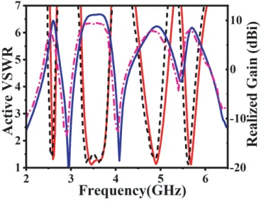
Figure 7. Simulated and measuredS-parameters and realized gains for the proposed antenna.
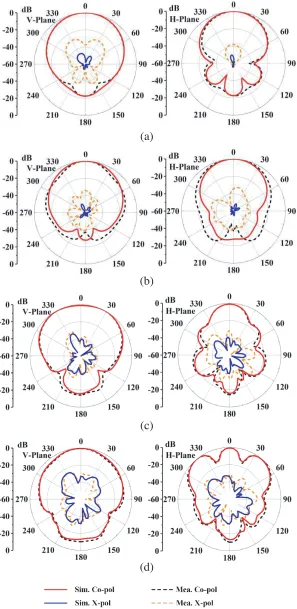
connected to matched loads. Fig. 7 shows the measured results when port 1 and port 2 are differentially fed. Good agreements can be obtained between the measured and simulated results. The operation bands of the proposed antenna are 2.54–2.60 GHz, 3.30–3.76 GHz, 4.76–4.94 GHz, and 5.56–5.67 GHz for active VSWR < 2. The average realized gains are 8.1 dBi, 9.3 dBi, 7.9 dBi, and 7.8 dBi. Besides, deep roll-offs of the realized gain can be observed outside each operation band. Fig. 8 illustrates the simulated and measured radiation patterns for the proposed antenna at the four operation bands. When the antenna operates at 2.58 GHz and 3.5 GHz, stable unidirectional radiation patterns are obtained with low cross-polarization levels of better than−30 dB. However, when the antenna operates at 4.8 GHz and 5.6 GHz, the sidelobe levels get higher. The main reason is that the antenna works under higher-order modes at the two bands. It is worth mentioning that the cross-polarization level is better than
−26 dB across the two bands.
A comparison is made between our work and the references as shown in Table 1. It can be seen
Table 1. Comparison of the proposed antenna and the reference antennas.
Reference Operation band Polarization Filtering response Technique realization
[2] 4 single no Stub-loaded resonator
[3] 2 dual yes Stub-loaded resonator
[8] 2 single yes Open-circuit stub
[10] 2 single yes Open-circuit stub
[11] 3 single yes Open/short-circuit stub
(a)
(b)
(c)
(d)
that our operation bands are more than the others except for [2]. However, the filtering response is not taken into consideration in [2]. Among the other designs, the filtering responses are mainly generated with filtering structures that are integrated into feedlines. Although good filtering responses can be obtained, the design process may be difficult. In summary, the proposed antenna in our work has more operation bands and good filtering response with simpler structure.
4. CONCLUSION
In this paper, a multi-band, dual-polarized patch antenna with bandpass filtering response is proposed. With the introduction of a Γ-shaped feeding structure and U-shaped slots, more resonant modes are generated, as well as two extra radiation nulls. As there is no filter circuit added, the proposed antenna has a simple structure, which is easier to design for antenna engineers. Besides, the proposed antenna has some other advantages such as low costs, easy fabrication, and a very low profile of 0.05λ (λ is the wavelength at 2.57 GHz in free space). Simulated and measured results illustrate four operation bands with good filtering response. Unidirectional and stable radiation patterns with low cross polarization levels of better than −26 dB are also achieved. Moreover, some frequency bands of 5G communications have been covered by the proposed antenna, which makes it a good candidate for 5G wireless communication systems.
REFERENCES
1. Yao, Z. H. and D. Chen, “A novel filtering antenna using dual-mode resonator,” Progress In Electromagnetics Research Letters, Vol. 58, 113–118, 2016.
2. Mao, C. X., S. Gao, Y. Wang, et al., “A novel multiband directional antenna for wireless communications,”IEEE Antennas and Wireless Propagation Letters, Vol. 16, 1217–1220, 2016. 3. Mao, C. X., S. Gao, Y. Wang, et al., “A shared-aperture dual-band dual-polarized
filtering-antenna-array with improved frequency response,”IEEE Transactions on Antennas&Propagation, Vol. 65, 1836–1844, 2017.
4. Qian, J. F., F. C. Chen, Y. H. Ding, et al., “A wide stopband filtering patch antenna and its application in MIMO system,”IEEE Transactions on Antennas & Propagation, Vol. 67, 654–658, 2018.
5. Tang, H., C. W. Tong, and J. X. Chen, “Differential dual-polarized filtering dielectric resonator antenna,” IEEE Transactions on Antennas & Propagation, Vol. 66, 4298–4302, 2018.
6. Hu, P. F., Y. M. Pan, X. Y. Zhang, et al., “A compact quasi-isotropic dielectric resonator antenna with filtering response,”IEEE Transactions on Antennas&Propagation, Vol. 67, 1294–1299, 2019. 7. Hu, P. F., Y. M. Pan, X. Y. Zhang, et al., “A filtering patch antenna with reconfigurable frequency and bandwidth using F-shaped probe,”IEEE Transactions on Antennas & Propagation, Vol. 67, 121–130, 2019.
8. Zhang, X. Y., Y. Zhang, Y. M. Pan, et al., “Low-profile dual-band filtering patch antenna and its application to LTE MIMO system,” IEEE Transactions on Antennas & Propagation, Vol. 65, 103–113, 2017.
9. Lin, C. K. and S. J. Chung, “A compact filtering microstrip antenna with quasi-elliptic broadside antenna gain response,”IEEE Antennas and Wireless Propagation Letters, Vol. 10, 381–384, 2011. 10. Li, Y., Z. Zhao, Z. Tang, and Y. Yin, “A low-profile, dual-band filtering antenna with high selectivity for 5G sub-6 GHz applications,” Microw. Opt. Technol. Lett., 1–6, 2019, https://doi.org/10.1002/mop.31891.
11. J. F. Q., F. C. Chen, and Q. X. Chu, “A novel tri-band patch antenna with broadside radiation and its application to filtering antenna,”IEEE Transactions on Antennas & Propagation, Vol. 66, 5580–5585, 2018.
13. Ding, C. F., X. Y. Zhang, Y. Zhang, et al., “Compact broadband dual-polarized filtering dipole antenna with high selectivity for base station applications,” IEEE Transactions on Antennas &
Propagation, Vol. 66, 5747–5756, 2018.
14. Alkurt, F. O., O. Altintas, A. Atci, et al., “Antenna-based microwave absorber for imagingin the frequencies of 1.8, 2.45, and 5.8 GHz,” Optical Engineering, Vol. 57, 113102, 2018, doi: 10.1117/1.OE.57.11.113102.