Scholarship@Western
Scholarship@Western
Electronic Thesis and Dissertation Repository
8-28-2017 12:00 AM
lmproving Microcontroller and Computer Architecture Education
lmproving Microcontroller and Computer Architecture Education
through Software Simulation
through Software Simulation
Kevin Brightwell
The University of Western Ontario
Supervisor
McIsaac, Kenneth
The University of Western Ontario
Graduate Program in Electrical and Computer Engineering
A thesis submitted in partial fulfillment of the requirements for the degree in Master of Engineering Science
© Kevin Brightwell 2017
Follow this and additional works at: https://ir.lib.uwo.ca/etd
Part of the Computer and Systems Architecture Commons, Digital Circuits Commons, and the
Engineering Education Commons
Recommended Citation Recommended Citation
Brightwell, Kevin, "lmproving Microcontroller and Computer Architecture Education through Software Simulation" (2017). Electronic Thesis and Dissertation Repository. 4886.
https://ir.lib.uwo.ca/etd/4886
This Dissertation/Thesis is brought to you for free and open access by Scholarship@Western. It has been accepted for inclusion in Electronic Thesis and Dissertation Repository by an authorized administrator of
In this thesis, we aim to improve the outcomes of students learning Computer Architecture
and Embedded Systems topics within Software and Computer Engineering programs. We
de-velop a simulation of processors that attempts to improve the visibility of hardware within the
simulation environment and replace existing solutions in use within the classroom. We
desig-nate a series of requirements of a successful simulation suite based on current state-of-the-art
simulations within literature. Provided these requirements, we build a quantitative rating of
the same set of simulations. Additionally, we rate our previously implemented tool, hc12sim,
with current solutions. Using the gaps in implementations from our state-of-the-art survey, we
develop two solutions. First, we developed a web-based solution using the Scala.js compiler
for Scala with an event-driven simulation engine through Akka. This Scala model implements
a VHDL-like DSL for instruction control definition. Next we propose tools for developing
cross-platform native applications through a project-based build system within CMake and
a continuous integration pipeline using Vagrant, Oracle VirtualBox and Jenkins. Lastly, we
propose a configuration-driven processor simulation built from the original hc12sim project
that utilizes a Lua-based scripting interface for processor configuration. While we considered
other high-level languages, Lua best fit our requirements allowing students to use a modern
high-level programming language for processor configuration. Instruction controls are defined
through Lua functions using high-level constructs that implicitly trigger low-level simulation
events. Lastly, we conclude with suggestions for building a new solution that would better
meet requirements set forth in our research question building from successful aspects from this
work.
Keywords: Embedded systems, computer architecture, computer architecture simulation,
pedagogy, cross-platform application development
I would like to acknowledge my advisor Dr. Kenneth McIsaac for his continued support
and mentorship throughout my undergraduate and graduate works. Thank you for taking the
time to debug, construct, and destruct ideas from all angles. Your direction has allowed me to
grow as a research, engineer and academic.
I would like to thank my peers in Dr. McIsaac’s lab for providing laughs and support over
the course of this work. I would like to extend the same thanks to those in Dr. Xianbin Wang
and Dr. Roy Eagleson’s labs for being supportive peers through forced geographic association.
I would like to thank my father and step mother, John and Amy Brightwell, and my mother
and step father, Kyra Hanson and Wilf Wityshyn, for listening to my complaints, failures and
successes throughout this work and never batting an eye of support. I would like to thank Mr.
Brad de Vlugt, Mr. Kyle Fricke, and Ms. Trinette Wright for their continued support over the
course of this work providing friendship and a talking post repeatedly. Lastly, I would like
to thank my boyfriend Eric Pattara for his love, continuous support and delightful immaturity
when I needed that most.
To any and all of my colleagues, peers, family and friends thank you for your support.
Abstract i
Acknowledgements ii
List of Figures vi
List of Tables viii
List of Listings ix
List of Definitions xi
List of Appendices xiii
1 Introduction 1
1.1 Research Question . . . 2
1.2 Motivation . . . 2
1.3 Problem Statement . . . 9
1.3.1 Software versus Hardware . . . 14
1.4 Contributions . . . 14
2 Survey of other and previously completed works 17 2.1 Previous Work: hc12sim . . . 17
2.1.1 Software Design . . . 18
Instructions . . . 19
Hardware Simulation . . . 21
2.2 Evaluation of existing simulation technologies . . . 23
2.2.2 hc12sim . . . 24
2.2.3 ShelbySim . . . 25
2.2.4 EDCOMP: Flexible Web-Based Educational System . . . 27
2.2.5 p88110: A Graphical Simulator for Computer Architecture and Orga-nization Courses . . . 29
2.2.6 EASE - An Extensible Architecture Simulation Engine . . . 31
2.2.7 TinyCPU and TinyCSE: Hardware simulations for education . . . 32
2.2.8 CPU Sim . . . 35
2.2.9 Emumaker86: A Hardware Simulator for Teaching CPU Design . . . . 40
2.3 Summary . . . 42
3 procsim.scala: Scala-based event-driven processor simulation for the web 45 3.1 Introduction to Scala and Akka . . . 45
3.2 Event- and Message-driven Simulation . . . 48
3.3 Scala.js - Scala transpiler for JavaScript . . . 49
3.4 Implementation of procsim.scala . . . 50
3.4.1 VHDL-like DSL configuration and runtime-based instructions . . . 50
3.4.2 Akka-based Components . . . 52
3.5 Technology Challenges . . . 54
3.6 Analysis of Requirements . . . 56
4 Developing cross-platform C++applications 59 4.1 Modernizing hc12sim . . . 60
4.2 Cross-platform development . . . 60
4.2.1 Access to multiple platforms within a single host platform . . . 62
4.2.2 Building with cross-platform tools . . . 64
4.3 Testing Infrastructure . . . 66
4.4 Improving developer work flows within CMake . . . 68
5 Lua-based configuration-driven processor simulation 76
Python . . . 77
JavaScript . . . 78
Java and Scala . . . 81
Lua . . . 82
Scripting language decision . . . 84
5.1.2 Lua integration . . . 85
5.1.3 Configuration versus Simulation entities . . . 90
5.2 Lua-based Configuration . . . 91
5.3 Instruction definition . . . 99
5.3.1 Opcode and Operand encoding . . . 99
5.3.2 Instruction execution: Side-effect-based compilation . . . 102
5.4 Project design and technical flaws . . . 109
5.4.1 Compiler strain . . . 109
5.4.2 Loss of pedagogical gains for high- versus low-level constructs . . . 110
5.5 Analysis of Requirements . . . 112
6 Conclusion 114 6.1 Contributions . . . 115
6.2 Recommendations . . . 116
6.3 Future Work . . . 119
Bibliography 120 A Procsim headers 132 A.1 Memory Components . . . 132
A.2 Time . . . 143
A.3 Encoding . . . 155
A.4 Core . . . 164
Curriculum Vitae 171
1.1 ECE 3375 - Course Sentiment Analysis Results [24], [25] . . . 4
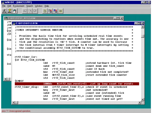
1.2 WinIDE12Z Integrated Development Environment [26] . . . 6
1.3 Freescale M68HC12 development board built by Western Engineering
Elec-tronics Shop for use in ECE 3375 . . . 6
1.4 StackOverflow 2016 developer survey results for desktop operating systems
[36, Sec. VIII. Desktop Operating System] . . . 12
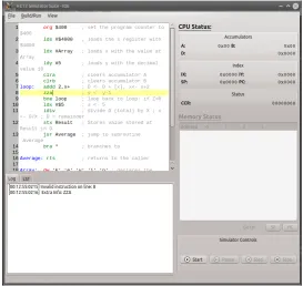
2.1 hc12ide Integrated Development Environment showing a student error in an
incorrect specification of an instruction mnemonic. . . 18
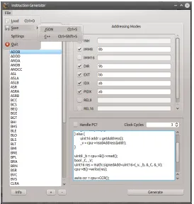
2.2 hc12sim Instruction Generator showing the meta information for addressing
modes, execution, and output. . . 20
2.3 Block diagram of TinyCPU showing the internal architecture [29, p. 869] . . . 33
2.4 State chart of TinyCPU execution path [29, p. 869] . . . 33
2.5 TinyCSE execution state diagram modified from Figure 2.4 to include
inter-rupts (broken lines show changes from TinyCPU [29]) [28, p. 640] . . . 34
2.6 CPU Sim 4.0.0 IDE during debugging with Assembly Editor open [52] . . . 37
2.7 CPU Sim Machine Instruction configuration interface showing combination of
fields to create a microcode and an assembly instruction. . . 38
2.8 CPU Sim 4.0.0 IDE module specification dialog showing modification of
Trans-fer Register to Register Array microinstruction [52] . . . 39
2.9 Emubuilder86 Control Builder: State machine definition [56, p. 325] . . . 41
3.1 Graphical representation of three Actors sending bi-directional messages [70]. . 48
5.1 URISC hardware architecture with microcodes [6]. . . 92
1.1 ECE 3375 Course “Level of enthusiasm before taking the course” as reported
by undergraduate students following course completion [24], [25]. . . 5
2.1 Qualitative requirement rating of hc12sim [40] . . . 25
2.2 Qualitative requirement rating of ShelbySim [35], [45] . . . 27
2.3 Qualitative requirement rating of EDCOMP [30] . . . 29
2.4 Qualitative requirement rating of p88110 [31] . . . 31
2.5 Qualitative requirement rating of EASE [34] . . . 32
2.6 Qualitative requirement rating of TinyCPU/TinyCSE [28], [29] . . . 35
2.7 Qualitative requirement rating of CPU Sim [39] . . . 40
2.8 Qualitative requirement rating of Emumaker86 [56] . . . 42
2.9 Summary of Evaluation for Simulators . . . 43
3.1 Summary of requirement matching for procsim.scala. . . 58
5.1 Summary of requirement matching for procsim. . . 113
2.1 Sample of the JSON output used to generate code within hc12sim. BEQ
per-forms a branch if two values were equal. . . 21
3.1 An example DSL source written in Scala to emulate BASIC called “Baysick” [1] 47 3.2 Normal definition of Instruction. . . 52
3.3 Reified definition of Instruction. . . 52
3.4 Clock pulse message for Akka . . . 54
3.5 Actorthat listens forClockPulsemessages and prints the time. . . 55
4.1 Vagrant file that describes a Ubuntu 14.04 box with modern GCC 5.X and LLVM Clang 3.7 compilers installed. . . 65
4.2 CMake script showing how two test suites, time and encoding, are defined as part of a project,core . . . 71
4.3 Test output from CTest [2] from Microsoft Visual Studio Community 2015 for procsim showing organization provided by CMake configuration. . . 75
5.1 Example of exposing a C++class to Python [3]. . . 79
5.2 Table used to describe project information for the Lua.org site [4] . . . 84
5.3 class playerthat holds two fields, one for hitpoints (hp) and one for bullets a player has (adapted from [5]). . . 87
5.4 Utilize theclass playerwithin a Lua script (adapted from [5]). . . 88
5.5 Required bindings to allow utilization of class player from Lua (adapted from [5]). . . 89
5.6 Configuration of Figure 5.1 for the URISC processor [6]. . . 93
5.7 (Continued) Configuration of Figure 5.1 for the URISC processor [6]. . . 94
5.8 Clockconfiguration for the processors main clock (cut from Listing 5.6). . . . 96
5.11 Processor utilizing memory mapping functionality. . . 100
5.12 Encoding of the opcode and operands of theSUBLEQ Instruction(cut from Listing 5.6). . . 101
5.13 Execution definition for theSUBLEQ Instruction(cut from Listing 5.6). . . . 104
5.14 Local variable definitions within anInstruction:exec()method. . . 106
A.1 Source forprocsim/memory/MemoryUnit.hpp. . . 132
A.2 Source forprocsim/memory/Register.hpp. . . 140
A.3 Source forprocsim/time/Clock.hpp. . . 143
A.4 Source forprocsim/time/AsyncTimerReceiver.hpp. . . 146
A.5 Source forprocsim/time/Timer.hpp. . . 148
A.6 Source forprocsim/encoding/Algorithm.hpp. . . 155
A.7 Source forprocsim/encoding/Code.hpp. . . 158
A.8 Source forprocsim/encoding/Operand.hpp. . . 162
A.9 Source forprocsim/core/Instruction.hpp. . . 164
A.10 Source forprocsim/core/Proc.hpp. . . 168
Application Programming Interface (API) A software layer between a developer that
uti-lizes a library or program and the library or program itself. APIs are designed to hide
imple-mentation details and ease developer usage.
Arithmetic Logic Unit (ALU) In a computer system, ALUs are responsible for performing
arithmetic operations on binary input such as addition, shifts, multiplication, division.
Complex Instruction Set Computer (CISC) A type of microprocessor architecture that
uti-lizes larger, instructions aiming to reduce the software instructions required to complete a task
[7], [8]. CISC architectures are used in most general applications based on Intel®x86 ISA [9]. Domain-Specific Language (DSL) A computer programming language that is specialized to
a particular application space (domain). For example, HTML is a DSL used to layout websites
but could not be used to program an embedded device. Similarly, C++is an excellent language
for creating applications but is very poor at describing layout for a webpage.
Embedded Systems Topics involving characteristics of embedded systems, techniques for
embedded applications, parallel input and output, synchronous and asynchronous serial
com-munication, interrupt handling, applications involving data acquisition, control, sensors, and
actuators, implementation strategies for complex embedded systems [10, p. 118]
Computer Architectures Topics involving computer organization and architecture.
Includ-ing, but not limited to processor organization, instruction set architecture, memory system
organization, performance, and interfacing fundamentals [10, p. 118]
Graphical User Interface (GUI) Any interface based on rendering graphically, for example
a window with buttons.
physical circuit layout from the gate and register transfer level [11].
Instruction Set Architecture (ISA) The design of an interface between software and
hard-ware designs in a computing environment. Including but not limited to assembly language and
microcode design. Once realized, an ISA is referred to as an Instruction Set Implementation.
Integrated Development Environment (IDE) A tool used for developing hardware and
soft-ware components that provides integrated tools for the current development context. For
ex-ample, Xilinx ISE [12], JetBrains IntelliJ IDEA1, or Eclipse2.
Just-in-Time Compiler (JIT) A traditional compiler that operates at runtime to perform
op-timization on running code. JITs are typically found in interpreted languages such as on the
JVM or in JavaScript. JITs vastly improve the runtime of the code they compile as they often
utilize semantics such as code path tracing and known constant analysis that is not necessarily
available at compile-time.
Reduced Instruction Set Computer (RISC) A type of microprocessor architecture that
uti-lizes small, highly-optimized set of instructions used to reduce power and improve instruction
performance [7], [8]. These architectures are commonly used in embedded, mobile (ARM),
and high-performance server applications (IBM POWER).
Reification The process by which an abstraction (usually aStringrepresentation) of software
is converted into an explicit object. For example, JavaScript’s eval(script) compiles and
executes the content of thescript passed and any state changes within the script are applied
to the global scope.
Transpiler A compiler that compiles one language to another. Typical transpilers convert one
language to JavaScript to allow use in web applications. For example, Scala.js and TypeScript
both compile their respective language to JavaScript.
1Available:https://www.jetbrains.com/idea/ 2Available:http://www.eclipse.org
Appendix A Procsim headers . . . 132
Introduction
Embedded systems and computer architectures are a critical part of both computer and software
engineering undergraduate programs [10], [13]–[16]. Over time, it is expected that knowledge
of embedded systems and computer architectures will be required given projections of rapid
growth of positions in both systems software developers (+13%) and computer occupations
(+12.5%) for 2020 [17]. At our institution, Western University, four courses cover embedded
systems and computer architectures,ECE 3375 - Microprocessors and Microcomputers,ECE
3389 - Computer System Design, ECE 3390 - Hardware/Software Co-Design and ECE 4460
- Real-time and Embedded Systems [18]. These topics are taught through the use of industry
focused software such as Intel Quartus Prime (formerly Altera Quartus II) [19], Xilinx ISE
WebPACK [12] or WinIDE [20]. These established industry tools are complex and powerful
for industry but we have anecdotally found students often feel overwhelmed during use.
Ad-ditionally with the prevalence of high-level programming languages, embedded systems work
has become increasingly difficult for students. Students are troubled connecting high-level
concepts to low-level details in computer architectures largely due to theoretical
ities between lecture materials and the “black box” of hardware.
1.1
Research Question
This thesis attempts to answer the following research question:
Can improvements and increased usage of software simulation technologies within
laboratory exercises in undergraduate embedded system and computer architecture
courses improve student engagement in laboratory and assignment exercises?
Given the overall research question, there exist sub-questions:
1. Are simulation software beneficial to improvements in student outcomes in computer
and software engineering programs?
2. What elements of simulation software should be required for successful implementation
within an undergraduate course?
Each of these questions are elaborated in further sections.
1.2
Motivation
Students in computer engineering have a growing requirement to have strong knowledge of
both embedded systems and computer architectures due to increases in computer engineering
careers [10], [17]. Unfortunately, many students do not show enthusiasm for subjects
surround-ing computer architecture and embedded systems [16], [21]. This lowered enthusiasm reduces
At Western University, students in all students in Electrical & Computer Engineering
de-gree programs must take the course ECE 3375 - Microprocessors and Microcomputers [22],
[23]. We utilized the feedback students provide through end-of-semester course evaluations to
gauge student enthusiasm and sentiment regarding ECE 3375. In order to extract sentiment,
we applied a simplistic approach. If a comment was overtly positive or negative, we stated it
was positive or negative respectively. If a comment was indistinguishable, we erred to
neu-tral to try and remove our own biases. Unfortunately due to confidentiality, we are unable to
provide these comments directly. As seen in Table 1.1, student enthusiasm for ECE 3375 at
Western University is mixed. Unfortunately, our collected data is not broken down between
computer and software engineering – both are required to take this course. Additionally, with
primitive sentiment analysis applied to results from 2013 and 2014 [24], [25], shown in
Fig-ure 1.1a, we can see that after completion of the course, students are pleased overall with the
course content itself as approximately 73% of students found the experience positive.
How-ever, by filtering comments regarding the laboratory sessions and applying the same technique
for sentiment as the course, shown in Figure 1.1b, we find that students are likely very unhappy
with the lab components as approximately 33% stated negative reviews and only 24% stated
positive reviews. Due to time constraints, we were unable to compile a formal survey due to
time required for ethics approvals and program duration.
Researchers have found that there are concerns with low-level hardware constructs being
taught to high-level Computer Science, Software Engineering and Computer Engineering
grad-uates [15], [16]. Additionally, we can corroborate the following claims by Ristov et. al. [15]
regarding student’s opinions on microprocessor courses:
ex-(a) Course Sentiment
(b) Lab Sentiment
ercises. Students could not transfer knowledge gained from either lectures or
the-oretical exercises to practical exercises [. . . ]
Observation 2. Inappropriate programming and simulation environment. Students
faced installation problems [. . . ] leading to aversion to presented material and
exercises.
Observation 3. No “real world” application. [. . . ] Students [raise] the main
ques-tion: Why we are learning this, and how and where shall I use it?
([15, p. 340])
Given our first-hand experiences in both taking and assisting in the instruction of ECE 3375
and ECE 3390, these claims are repeated by students during laboratory exercises and review
sessions creating hostility towards the subject matter. In a direct example supporting
observa-tion 2, students in ECE 3375 use the WinIDE12Z Integrated Development Environment [20],
shown in Figure 1.2, for completing laboratory work ranging from simple “hello world”
as-sembly programs to hardware interfacing. In ECE 3375, students found WinIDE complicated,
frustrating and “outdated” [24], [25] directly supporting both observation 2 and observation 3.
Additionally students found it difficult to move from lecture material that presented embedded
systems as “translucent” devices composed of inner components to the literal “black box” of
the physical hardware shown in Figure 1.3.
With sentiment analysis and the comments provided by students in course evaluation
feed-Initial Level of Enthusiasm
Year 2013 2014 Total
High % 45.6 57.8 53.0
Medium % 54.2 33.3 41.6
Low % 0.0 8.9 5.4
Total # 59 90 149
Figure 1.2: WinIDE12Z Integrated Development Environment [26]
back [24], [25], we extracted several common propositions for improving laboratory sessions:
Proposition 1. Increase the number of laboratory sessions
Proposition 2. Add tutorial sessions to course schedule
Proposition 3. Change course material to use modern processors
Proposition 4. Replace laboratory microcontrollers with different hardware
Proposition 5. Improve and/or replace software within laboratory
All of these considerations were brought to the course instructor and limitations were noted
for each. For Propositions 1 and 2, while the addition of more hands-on experience has been
shown to improve student outcomes [15], [16], due to the large amount of financial resources
required to add more laboratory sessions, this option is likely unavailable for many programs.
In addition, due to the layout of the current course laboratory sessions, there does not exist
enough weeks in the 12-week course to add more sessions given current staffing resources. It
is reasonable to assume that these issues are prevalent at other institutions. Thus, both
Propo-sitions 1 and 2 can not be implemented given financial and temporal restrictions.
Proposition 3 asks the instructor to change the current course material to use more modern
hardware and software architecture. There are several reasons why this is not beneficial to the
improvement of learning outcomes. The current architecture used is the Freescale M68HC12.
This architecture provides a simple Complex Instruction Set Computer (CISC) Instruction Set
Architecture (ISA) with only four 16-bit addressable registers (SP,PC,X,Y); two eight-bit
M68HC12 assembly is similar to current Intel® x86 processors [9]. Parallels between ar-chitectures allows instructors to use more simple arar-chitectures that still allow students to apply
concepts to newer architectures while simultaneously reducing the cognitive “base knowledge”
required to succeed. Using simpler architectures like the Ultimate Reduced Instruction Set
Computer (URISC, [6]) has been shown to be very beneficial to improving student outcomes
[6], [28]–[31]. Additionally, by changing course materials, it leads into changing the
labora-tory hardware which Proposition 4 discusses. Unfortunately, replacing laboralabora-tory equipment
requires significant investment and with justifications for Proposition 3 showcasing that there
is not noticeable improvements in learning outcomes, the cost-benefit analysis does not prove
worthwhile to adjust both Propositions 3 and 4.
The last proposition, Proposition 5 is the most attainable. Researchers have found that
improving software technology in the classroom and laboratory can vastly improve the
learn-ing outcomes of students while improvlearn-ing engagement [10], [15], [16], [21], [30], [32]–[35].
Students within ECE3375 are immediately presented with the interfaces shown in Figure 1.2.
Students have expressed immense frustrations with the software when used in the laboratory
exercises and often encounter hardware issues that are not caused by their own work [24], [25].
Other researchers have found hardware solutions problematic with hardware-specific problems
common such as broken peripherals and unconnected pins [21]. These errors are hard to
de-bug, if not impossible for students with no prior knowledge. Teaching assistants and instructors
are often unable to debug these issues without the aid of technicians. These hard-to-diagnose
hardware issues lead to strained teaching resources and frustrations, supporting a large
poten-tial gain by replacing this ageing software with new tooling. Given these justifications, this
within the ECE 3375 course and propose a configurable solution for others to utilize in other
courses.
1.3
Problem Statement
Our analysis of the current state of the ECE 3375 course showcased the pervasive dislike and
discomfort with the current laboratory exercises [24], [25]. Given previous analysis, we chose
to improve the current software used within the laboratory exercises and the classroom. To do
this, a current survey of known technologies is completed to ascertain whether a new solution
should be created or an existing solution will provide the requirements. Therein the formal
problem becomes:
Can a solution be provided to students that is configurable for hardware and
soft-ware interfaces and showcases the connection between hardsoft-ware and softsoft-ware
while focusing on pedagogy rather than industry performance?
While the formalization is accurate, “striking the right balance between teaching sufficient
details of hardware components and their working principles, and important theoretical
con-cepts useful for programming the computer is always a challenge.” ([34]) From reviewing
many existing software solutions to this problem, we propose the following requirements for a
successful solution:
Requirement 1.Must be available for use outside of the laboratory on personal computers
including all major desktop platforms (e.g. Windows, macOS and Linux)
Requirement 2.Provide a student configurable system for different ISAs including
2.a. microcode and assembly instructions
2.b. execution semantics (i.e. how a processor executes code)
2.c. internal hardware components and connections
2.d. external peripherals
Requirement 3.Focus on pedagogy over simulation accuracy as best as reasonable
Requirement 4.Simulations must allow:
4.a. viewing of the current state of hardware components
4.b. stepping at the assembly and microcode level
4.c. setting of breakpoints to ease debugging
4.d. connecting “external” peripheral components
Requirement 5.Provide a modern user interface that is similar to current high-level
program-ming IDEs
Requirement 1: Personal computer usage. Requirement 1 outlines that any software must
be cross-platform. StackOverflow’s Developer survey [36] found that approximately 47.9% of
those surveyed used a non-Microsoft Windows environment (macOS or Linux). The metrics
recorded for 2016 desktop operating systems are shown in Figure 1.4. While other metrics
show that over 80% of computers are Microsoft Windows [37], we believe the StackOverflow
survey is better given students in computer and software engineering programs likely go on to
become hardware or software developers [36, Sec. II. Developer Profiles]. Further,
op-erating systems between 2013 and 2016 [36]. StackOverflow’s results imply that this project’s
solution must run on all three major operating systems with minimal effort to allow students to
perform out-of-classroom exercises.
Requirement 2: Expanded hardware/software configuration. As stated within the Com-puter Engineering Curricula 2016:
One area of concern to the computer engineer is the software/hardware interface,
where difficult trade-offdecisions often provide engineering challenges.
Consid-erations on this interface or boundary lead to an appreciation of and insights into
computer architecture and the importance of a computers machine code. At this
boundary, difficult decisions regarding hardware/software trade-offs can occur, and
they lead naturally to the design of special-purpose computers and systems. ([10,
p. 32])
Requirement 2 enables students to design and configure all of the hardware/software
compo-nent interactions. This enables students to have a stronger understanding of ISA design. While
many tools have this flexibility (discussed later in Section 2.2), many of the currently used,
industry-grade solutions provide over-complicated and powerful options that are
overwhelm-ing for students. It is expected that disorientation by complication of user interfaces for users
may have an impact on performance, production, motivation and morale of users [38]. This
“user hostility” must be reduced for students as they are less likely to have the motivation that
an industry professional may have [30]. As the focus of this thesis is to improve student
learn-ing outcomes, the amount of irrelevant options for learnlearn-ing must be reduced as a trade-offin
Operating System
Linux
Ubuntu 12.3
A
pple
macOS 26.2
W
indo
ws
7 22.5
Debian 1.9 10 20.8
Fedora 1.4 8 8.4
Mint 1.7 Vista 0.1
Other 4.4 XP 0.4
Total 21.7 Total 26.2 Total 52.1
Requirement 3: Pedagogical versus accuracy trade-offs. While pedagogy is the most im-portant aspect of a teaching simulation, we also acknowledge that it is not a binary scenario.
Any such solution must be accurate enough for students to understand underlying concepts
while being high-level enough to not inhibit their learning outcomes by overwhelming them.
Requirement 4 outlines the software requirements that simulations must meet while still
re-specting Requirement 3. Simulations are an important practical tool for students to see the
inner workings of hardware components and attempts to increase the transparency into the
long-standing “black-box” of hardware for embedded systems courses. For computer
architec-ture courses, simulation tools are required for debugging and implementing ISAs.
Requirement 4: Run-time simulation features. We believe students best learn from fully
understanding concepts from a bottom-up approach. With the ubiquitous nature of debugging
facilities in modern software environments, we assert any successful software simulation must
have similar capabilities for the hardware it is simulating. This includes breakpoints and
view-ing of registers as “variables” within the context. These features give students a familiarity and
a view inside the workings of a simulation.
Requirement 5: Modern interface. Requirement 5 attempts to reduce the overhead gap of
working with new tools by reducing differences in features for students. Decreasing the overall
cognitive load by integrating similar styles and controls to existing tools within interfaces will
1.3.1
Software versus Hardware
While providing a solution in software that emulates hardware we would like to discuss how
the hardware itself comes into teaching contexts. Some would argue that a “simulator may
perform the same actions as a hardware device, therein deprecating the use of hardware.” We
believe this is false. Students require the use of hardware to understand the physical nature
of the device being used. Many defects found in embedded systems projects are only found
by probing and testing hardware directly. By providing a better software simulation, we can
provide students with a home experience that is similar but not equivalent to working directly
with hardware. This new experience allows students to spend less time learning in the moment
on the hardware and more time understanding the physical nature of the devices [32], [39].
1.4
Contributions
This thesis is presented in an additional five chapters. This thesis discusses technical topics
regarding: existing and future pedagogical simulation technologies; development of web
ap-plications on modern platforms; building cross-platform native apap-plications; and integration of
scripting languages as configuration engines within a native application. We summarize the
contributions to each in the following sections.
Survey of other and previously completed works Within this chapter, we provide a
quanti-tative survey of existing simulator technologies in use today analysed against the requirements
procsim.scala: Scala-based event-driven processor simulation for the web We
investi-gate utilizing Scala and its compiler back-end Scala.js to build a parallel component-based
processor simulator for the modern web. Within this investigation, we showcase the following
contributions:
• A design for an asynchronous actor-based model for simulation of a custom processor architecture using distributed computing framework Akka
• A runtime, compiled VHDL-like DSL for specification of instructions within a custom ISA on top of Scala in the Java Virtual Machine and Scala.js
Developing cross-platform C++applications We discuss an anecdotal account of refactor-ing the hc12sim project into a modern C++environment. We discuss topics involving:
devel-oping a multi-platform project and providing adequate quality assurance, improving CMake
through custom build scripts, and improving application build times through optimization of
build artefact selection. The contributions outlined within this section are:
• An automated platform-specific testing infrastructure using Virtual Machines provisioned with Vagrant and Oracle VirtualBox automated with Jenkins’ Pipeline architecture
• A collection of project-based CMake scripts to isolate build targets while improving build times, reducing manual configuration and modularizing test specification
Lua-based configuration-driven processor simulation We discuss the use of scripting
en-gines in a native C++ application and their integration points; utilizing Lua as a scripting
integra-tion tools in parallel; and the pedagogical gains of a high-level language utilized for teaching
low-level concepts. We provide the following contributions:
• A design for a runtime configuration specification for custom processor architectures through Lua scripts
Survey of other and previously completed
works
2.1
Previous Work: hc12sim
In 2013, we worked collaboratively with colleague and fellow student Ramesh Raj to build a
behaviourally accurate simulator for the Freescale M68HC12 processor. This work was
com-pleted as part of our capstone project for a Computer Engineering degree from Western
Uni-versity [40]. This software was produced over 2013-2014 and had the following features:
1. Included memory element simulation for the Freescale M68HC12 architecture (e.g.
reg-isters, RAM, ROM)
2. Compile-time configurable microinstructions (addressing modes were not configurable)
3. Real-time simulation speeds for the Freescale M68HC12
4. Debugging of assembly code with runtime viewing of internal hardware components
5. Accurate CISC addressing modes as specified by Freescale M68HC12
6. Feature complete assembler creating exact machine code
7. Simple IDE for writing Freescale M68HC12 assembly code, compiling and simulating
it (shown in Figure 2.1)
Figure 2.1: hc12ide Integrated Development Environment showing a student error in an incor-rect specification of an instruction mnemonic.
2.1.1
Software Design
This project was written in C++ utilizing modern C++11 features such as lambdas, closures
and cross-platform libraries (e.g. Qt and Boost1). The primary design goals for the hc12sim
project were:
1. Support all three major platforms: Microsoft Windows, macOS, and GNU/Linux
2. Separate compiler and simulation components
3. Completely decouple any IDE from the simulation engine
4. Heavily unit-test all software components for validity confirmation
The goals set for the hc12sim project closely mimic the requirements set in Section 1.3. Given
these design goals, supporting technologies were assessed against the following requirements
(in order of priority):
1. User interface library available
2. Access to low-level types
3. Fast enough for simulation
While initially writing the software in Java utilizing Java’s Swing Toolkit and the Java Standard
Library, it was rewritten in C++due to access of low-level unsigned types, method references
and multithreading capabilities. Java’s current Java 8 release added these features, however the
Java 8 release was not available at the time of creation outside of “beta” environments.
Instructions
Due to the Freescale M68HC12 having over 200 instructions with multiple addressing modes
for each [27], the simulation and assembler libraries put heavy emphasis on generating code
to simplify writing and adding instructions. This allowed for generating multiple classes that
had all of the meta-information required for all stages of a program (writing, assembly,
generation required, a custom user interface was created to easily load and store data and
gen-erate C++code. Figure 2.2 showcases the interface created for code generation. The primitive
interface supported choosing an instructions supported addressing modes and writing the
trans-formations required within the small code window (bottom right of Figure 2.2). The generator
interface did not support any syntax highlighting for the C++ code required and performed
“magic” code injection upon generation [27, Table 3-1, p. 30] In addition to the user interface,
the generator back-end was built into a command-line tool that allowed the generation to be run
at compile time when hooked into build scripts (in this case, CMake [41]). The user interface
generated JSON entries similar to that shown in Listing 2.1. The “body” field is injected into a
method header for the execution engine and the other information is used in either compiling
or execution as meta-information.
1 {
2 "BEQ": {
3 "body": "
4 auto ccr = cpu->CCR();
5 bool _Z = ccr->get(Z);
6 if ( _Z ) {
7 int8_t rel = math::toSys<int8_t>(resbytes[0]);
8 cpu->PC()->inc(rel);
9 }
10 ",
11 "cycles": 1,
12 "handlePC": false, 13 "types": {
14 "REL8": "27"
15 }
16 },
17 }
Listing 2.1: Sample of the JSON output used to generate code within hc12sim. BEQ performs a branch if two values were equal.
Hardware Simulation
Physical modules within the simulation model were all individual custom classes. For example,
theA and Bregisters were of class Register<size_t width> where the widthtemplate
parameter defined the bit width of the Register. Regrettably, any special behaviours were
“decorated” on top of the base type creating many different types depending on how the
un-derlying component was used. Using the pattern of “compile-time constant templates” created
issues when trying to use these types in polymorphic aggregate containers. For example, if a
Register<8> A is defined and aRegister<16> X typeof Ais not the equal to typeof X
as templated types are created at instantiation time making the type of a variable a “new” type
(reuse happens when available) [42]. This created confusing class hierarchies and directly
maintainabil-ity. Of particular interest was the design of the class Timerand class TimerDependant
types which allowed for completely concurrent, event-based timing. While these concurrent
timing modules were fast and well designed, it created problems with discrete execution as
each component operates concurrently in separate thread contexts and can not be “stepped”
through without executing all of the threaded operations simultaneously. In addition, each
TimerDependant added a thread of execution adding runtime overhead to simulation while
reducing functionality of the simulation. Due to our ignorance at the time, neither thread
nor fork-join pools were used to reduce the thread “spin-up” performance penalty. Further,
the synchronization properties of this scheme reduced to near-synchronous execution with the
time taken to check locks and mutexes likely costing more time than the savings of parallelism
afforded – not to mention the required knowledge of maintaining a highly parallel code base.
Execution
The simulator implemented execution through anclass Executor that asynchronously
ex-ecutes the execution scheme specified by the Freescale M68HC12 [27, Sec. 4, p. 47] which
was implemented in terms of [44, p. 59]. The Executor utilized a fetch, decode, fetch (if
needed), execute loop for executing all instructions. The actual execution of an instruction was
completed directly by static code written in the instruction generation step (see Section 2.1.1
for more information). However, the generated code is run within a separate thread context to
keep the “clock” of the system running at a consistent speed. Of particular note, this
simula-tion could not handle interrupts or pipe-lining. Due to the reliance on the timing mechanisms
discussed in Section 2.1.1, the execution engine suffered from the same “synchronous”
result was an non-determinant clock skew over time.
2.2
Evaluation of existing simulation technologies
Presented in the following sections are a series of similar projects attempting to tackle the
same solution space as the work of this thesis. Each software tool is evaluated against the
requirements from Section 1.3. The intention of this evaluation is dual:
1. Find previous works that could be expanded upon and improved to match this thesis’
requirements rather than building a new solution in a “green field”
2. Extract features from other simulation technologies that are beneficial to future
technol-ogy
Each simulation project is rated based on the requirements out of five and totalled to create a
quantitative matrix of requirements. Each rating contains justifications for the rating assigned
following Section 2.2.2.
2.2.1
Methodology
Holistically, we attempted to find the best solution for each requirement outlined in Section 1.3.
To do this we created a ranking of each of our considered software and applied a rating of zero
to five with zero being the worst, and five being the best matching of each requirement. Within
this specification, we believe some requirements were not met by any of the software evaluated.
having a modern user interface. Our methodology allows for a relative, though opinion-based,
approach to contrasting existing solutions.
2.2.2
hc12sim
The hc12sim project was very immature and not well implemented in the presented state.
hc12sim managed to provide a solution for all of the required platforms when distributed as
individual platform specific binaries. The hc12ide was a desktop application and bound to the
technology choice of C++, there is no possibility of using the software outside the desktop
without large software porting efforts. Unfortunately, building C++applications such that they
can be distributed to cross-platform targets is labour intensive and very difficult without the
correct amount of knowledge – knowledge that was lacking at the time of authorship.
Bina-ries worked for some and often only worked with specific unknown environmental state
re-quirements (particularly with Windows environments). Regarding Requirement 1, the project
meets the requirement adequately, but does not do enough. Configuration of the ISA is
pro-vided through the JSON-driven mechanism for instruction generation but this mechanism only
worked as a compile-time configuration. If students wanted to change the ISA for their
proces-sor, it required rebuilding the entire project and testing to see that it worked manually. This was
aided by the use of the “Instruction Generator” described in Section 2.1.1 but does not remove
the requirement of building requiring a large compiler tool-chain. Further, without any support
for hardware configuration the project did not meet Requirement 2. hc12sim heavily favoured
Requirement 3 as it was intended to create a simulator that was behaviourally accurate to the
works.
The simulation interface allowed for debugging at an instruction level and setting break
points within execution contexts. During an execution, all component states could be viewed
– except for the memory. The project also assembled fully compliant machine code that could
potentially be programmed to a real machine. Unfortunately, peripherals and interrupts were
not supported. While including these flaws, the hc12sim project provides a poor match for
Requirement 4. Lastly, while the user interface does not have all of the features of a full IDE,
it did provide syntax highlighting, and assembler plus simulation controls in an easy to use
interface. Requirement 5 is adequately met, however it requires updates to the editor interface
to improve modern facilities.
Requirements R1 R2 R3 R4 R5 Total hc12sim [40] 3 1 4 2 3 15
Table 2.1: Qualitative requirement rating of hc12sim [40]
2.2.3
ShelbySim
ShelbySim is an education-oriented software system for designing, simulating, and evaluating
computer-engineering based applications [35], [45]. ShelbySim was designed surrounding a
new Java-like programming language including a compiler explicitly built around providing
extensive diagnostic information such as logging, tracing, and inspection capabilities. These
tools provide students with raw data for quantitative analysis, evaluation and reporting of their
designs. The software is open-source, though unavailable, and is written using Java allowing
full operating system independent support. Additionally, graphical visualizations of results are
subcompo-nents:
1. Software component - a custom programming language (Shelby), a compiler, and an
interpretation runtime
2. Hardware component - filling a similar niche to MultiSim, but with tight integration
with Shelby and its underlying tracing. Additional support exists for external component
integration
3. Simulation component - providing a deterministic and stochastic approach for recording
inputs and outputs to custom hardware simulations
ShelbySim provides evaluation criterion for students’ components and their underlying
sys-tems to aid in marking. The simulated components have parameters that are modifiable through
switches and sliders (e.g. {on, off}or a range from 0 - 100%). This gives students metrics to
evaluate their designs. Additionally, outputs are exported at runtime to Comma Separated
Value (CSV) files allowing for more in-depth analysis with external programs such as
Mi-crosoft Excel or MATLAB. This gives a flexible and realistic testing environment for student
learning.
Analysis of Requirements
For Requirement 1, ShelbySim is open-source and claims to run on all major platforms that
the Java Virtual Machine runs on, thus it should work on Windows, macOS and GNU/Linux.
ShelbySim is built as a custom programming language which is similar to Java but is used
as an HDL. Given the inherent flexibility of HDL languages, Requirement 2 is met, however
therein hurting Requirement 3. Further, ShelbySim focuses on compiler semantics and
hard-ware configuration over ISA and embedded systems knowledge. ShelbySim works well to
provide quality simulations as required by Requirement 4. Additionally, ShelbySim produces
comma-separated values of events which is useful for later analysis. Lastly, there does not
ap-pear to descriptions of a user interface component outside of graphical drawings. This does not
concretely fail the modern interface component for Requirement 5, but it does call into
ques-tion how students may react to a lack of a proper programming environment. Addiques-tionally,
there does not appear to be compiler features in place to utilize the custom ISA that a student
creates (e.g. assembler).
Requirements R1 R2 R3 R4 R5 Total ShelbySim [35], [45] 4 4 3 4 0 15
Table 2.2: Qualitative requirement rating of ShelbySim [35], [45]
2.2.4
EDCOMP: Flexible Web-Based Educational System
EDCOMP is an educational computer system and a web-based simulator that can be used to
cover computer architecture fundamentals; computer organization; computer arithmetic;
mem-ory hierarchies and organization; and simple input/output relations [30]. EDCOMP is written
in Java and runs inside of a Java applet within a web browser. The simulator supports
an-imation of instruction execution and allows students to write their own assembly programs,
compile them and view the status of the machine components. All parts have visual
compo-nents at multiple levels (i.e. module, combinational and sequential circuits). The simulation
can be run at several levels per clock cycle, per instruction and for the entire program. Further,
tim-ing diagrams allow students to see how components are interacttim-ing at a lower, discrete level.
This software aims to create a system that focuses on pedagogical learning rather than on
in-dustrial accuracy and lower complexity of the system. EDCOMP focuses heavily on graphical
representation to aid in student learning.
Analysis of Requirements
For Requirement 1, EDCOMP is written in Java and was previously run within a web browser
inside of a Java applet intending to open access to students with a low barrier to entry. However,
due to the deprecation of NPAPI2in Google Chrome, Chromium-based browsers, and Firefox,
this means that likely over 80% of students would not be able to use this software [46]–[51].
In addition to being unusable with today’s browsers, the system is also dated by the use of
applets and does not have modern editor features creating a gap between modern technology
and students therein failing to meet Requirement 5. The EDCOMP system is not completely
configurable as it is bound by purposeful reductions in features for pedagogical reasons. It
features a CISC-based architecture with configurable components, however the internal
con-nections can not be configured–only the size and “shape” of components. Thus, EDCOMP
does not meet Requirement 2. EDCOMP heavily focuses on learning and teaching and
show-cases the use of a user interface to improve simulation triggers in a pedagogically focused way.
The authors showcased the software by utilizing it within classrooms meeting Requirement 3.
Finally, the simulations described are extremely useful and thorough. These simulations
show-case powerful techniques in stepping and debugging and also triggering signals in meaningful
ways to show students how different components can interact. The quality of these simulations
strongly meets Requirement 4.
Requirements R1 R2 R3 R4 R5 Total
EDCOMP [30] 3 3 4 4 0 14
Table 2.3: Qualitative requirement rating of EDCOMP [30]
2.2.5
p88110: A Graphical Simulator for Computer Architecture and
Organization Courses
The p88110 attempts to cover many core topics in Computer Architecture and Organization
[31]. The authors reflected and have created a “one-size fits all” solution to try and replace
many heterogeneous simulators used in practice at the time. This software emulates the ISA
for the MC88110 microprocessor specifically – a RISC architecture. The authors intentionally
removed components to alleviate the amount of information for students to learn. The user
interface includes a view for the current simulation of components, and a simplistic, built-in
editor and simulation stepping at the instruction level and adding debugging breakpoints. The
simulator can be modified to execute in serial or parallel (super-scalar) modes. In parallel
mode, the four-stage pipeline of the MC88110 is implemented with static branch prediction
and delays. A unique feature is the use of built-in caches for instructions and memory. These
include configuration for time-to-read and write. During simulation, cache and branch
pre-diction hit and miss statistics are recorded for student analysis purposes. The authors have
implemented this simulator in class assignments and created an automated evaluation tool for
Analysis of Requirements
The authors claim that the p88110 simulator may be run on personal computers, however given
changing technologies and a lack of software description, we could not validate the software is
still able to run on current operating systems implying the system does not meet Requirement 1.
p88110 directly emulates the MC88110 system which is a similar system to the Freescale
M68HC12 and has been shown to be an excellent candidate for pedagogical purposes.
Re-quirement 2 states that a software must be able to be configured for multiple architectures
and while the MC88110 is a great candidate architecture specifically, p88110 is too limited to
meet this requirement. However, the engine configuration features presented by p88110 are
extremely powerful and useful. p88110 was developed for use within a classroom meeting
Requirement 3. Further, p88110 reduced realism to create a simpler architecture for students
to learn from – favouring pedagogy over accuracy. Additionally, the use of an automatic
mark-ing tool would reduce the overhead for teachmark-ing students and give students instant feedback
without requiring instructor interaction. The simulations provided by p81100 are thorough
and provide insight into statistical modelling of pipelined and cached architectures. This
in-formation is extremely relevant to computer architecture courses. However, the p88110 does
not support the use of peripherals or interrupts. Requirement 4 is not met due to lacking
fea-tures, though the statistical feedback provides an interesting insight for students to learn from.
Lastly, the interface is not modern and supports only simple features found in most editors.
The amount of dialogs created shows concern for focus when working with p88110 and does
Requirements R1 R2 R3 R4 R5 Total
p88110 [31] 1 1 4 3 1 10
Table 2.4: Qualitative requirement rating of p88110 [31]
2.2.6
EASE - An Extensible Architecture Simulation Engine
Extensible Architecture Simulation Engine (EASE) is a simulation engine focused on custom
simulations for classroom use [34]. EASE attempts to provide the following features:
• Support for multiple architecture types: RISC, CISC and URISC
• Provide a modular mechanism for simple extension
• Open-source software
• Portable to different platforms
The authors [34] reviewed the survey of simulation tools found in [33] and found the suggested
tools were inadequate for teaching simulation architecture courses based on their requirements.
Many put too much emphasis on RTL descriptions of the hardware and too little on ISA. EASE
provides three ISAs for use, a CISC, RISC and URISC within the project. EASE is written in
Java making it cross-platform. It comes with a very simple user interface written in Java Swing.
Analysis of Requirements
EASE is a very immature project without a lot of proven use–this makes it difficult to gauge
how effective it is. EASE focuses on pedagogy as it’s major requirement meeting
Require-ment 3. While the authors Require-mention new architectures may be added through impleRequire-mentation of
of the application to create a new architecture therein failing to meet Requirement 2. Given
that EASE is written with Java, all that is required to run the software is a Java runtime
mak-ing it cross-platform. However, [34] stated the software was available under the GNU Public
License v3, but the software is not currently available for consumption. Theoretically EASE
meets Requirement 1 through using the Java Virtual Machine for it’s environment but we could
not verify this. EASE does support step-based execution, however it has no support for debug
breakpoints. Further, there is no reference to stepping at the microcode level. Runtime viewing
of registers is available, however there is no way to view the memory. These outlined features
do not meet Requirement 4. Lastly, the user interface provided is very simple providing syntax
highlighting for a single file and simple debugging controls. The interface does not provide
modern editing features that students are accustomed to with most editors – failing to meet
Requirement 5.
Requirements R1 R2 R3 R4 R5 Total
EASE [34] 4 2 5 3 2 16
Table 2.5: Qualitative requirement rating of EASE [34]
2.2.7
TinyCPU and TinyCSE: Hardware simulations for education
TinyCPU is a teaching assignment designed to be used in a Masters of Science program in
em-bedded systems to teach students about computer architectures by having them incrementally
design a CPU (TinyCPU) [29]. TinyCPU has been used in a program described to be very
similar to Western University’s computer engineering program. TinyCPU runs in Verlilog and
is a simple stack-based machine. The full block diagram for TinyCPU is shown in Figure 2.3.
Figure 2.3: Block diagram of TinyCPU showing the internal architecture [29, p. 869]
Figure 2.4: State chart of TinyCPU execution path [29, p. 869]
consume. The entire CPU configuration is rigidly bound with:
• 16-bit word size
• 12-bit address space
• A single ALU
• Dual bus structure with a data bus (dbus) and address bus (abus)
The CPU is compiled with a Verlilog tool chain (e.g. Xilinx ISE) and loaded onto either a
hard-ware or softhard-ware-simulated FPGA to run. The execution model is intentionally simplistic for
improving ease of learning (shown in Figure 2.4). Given that TinyCPU is written in Verlilog,
it works well with existing industry tools such as ModelSim. Lastly, there exists a C compiler
TinyCSE is an extension to TinyCPU that provides a full system supporting hardware
in-terrupts that can interact with peripheral components like mice and keyboards [28]. TinyCSE
adds an I/O space memory mapping controller for interacting with peripherals. This allows I/O
components to “register” themselves into a position and programs in TinyCSE can read/write
to I/O components through memory mapping. Further, TinyCSE adds an interrupt flag that the
state machine utilizes to allow for hardware interrupts. These interrupts are extremely
impor-tant as this is how most hardware devices interact with a CPU. The modified state diagram is
shown in Figure 2.5. At an architectural level, interrupts are supported viaCALLand RETURN
instructions which branch to an interrupt routine and return from an interrupt routine
respec-tively while maintaining the stack.
Analysis of Requirements
For the purposes of analysis, this section will only consider TinyCSE as it is a super-set of
TinyCPU functionality. TinyCSE focuses on pedagogy first and foremost, but also focuses on
a hardware descriptor language, Verlilog. While Verlilog is a very powerful tool, it requires a
complicated tool-chain creating complications for the purpose of teaching introductory courses
– we do acknowledge the authors intended on utilizing TinyCSE for Masters of Science
stu-dents. Additionally, the software required for typical Verlilog environments is very expensive
and not accessible to the average student. This does not fully meet the requirements of
Require-ments 1 and 3. The simulations provided by TinyCSE provide more information than any other
simulator evaluated at the expense of complexity for the system and a high barrier of entry to
configure the simulator. This barrier creates a large enough gap that TinyCSE does not meet
Requirement 2 (see the discussion in Section 1.2 for a discussion on existing hardware IDEs).
While failing to meet Requirement 2, due to the level of simulation granularity Requirement 4
is easily met given existing industry tools. Lastly, the software provides no user interface of it’s
own and requires the use of a Verlilog IDE and FPGA programming software. These tools are
modern and updated regularly, however they often fail to have the editor/IDE features students
are used to not meeting Requirement 5.
Requirements R1 R2 R3 R4 R5 Total TinyCPU/TinyCSE [28], [29] 2 3 3 4 3 15 Table 2.6: Qualitative requirement rating of TinyCPU/TinyCSE [28], [29]
2.2.8
CPU Sim
CPU Sim is a Java CPU simulator written for use within a classroom environment [39]. CPU
Sim allows students to design, modify, and compare various computer architectures at the
register-transfer level and higher. Additionally, students may write and debug assembly code
for custom architectures. The simulator and IDE are written in Java, with the latter utilizing
Oracle’s JavaFX user interface. The software is currently available from [52] as “freeware.” In
to increase availability [53]. The user interface is feature rich allowing students to configure a
processor with:
• Hardware specifications (e.g. RAM word size, length),
• Hardware inter-connections,
• Processor microcodes,
• Assembly instructions,
These specifications gives students the ability to configure a nearly custom processor.
How-ever, using the current 4.0.10 release, configuration options are missing: clock speed changes,
CISC-like addressing modes, and peripheral support [52]. Using Java technologies allows CPU
Sim to work with the three major platforms as a desktop application. CPU Sim’s IDE provides
a modern assembly editor for custom architectures providing syntax highlighting, tabbed
ed-itor panes and simple eded-itor commands like find-and-replace. During a simulation, CPU Sim
allows students to view memory and register states. Figure 2.6 shows the IDE during a simple
simulation with a program written in a custom ISA open for editing. CPU Sim fully supports
debug points and step-based execution in it’s engine. Unfortunately the execution engine is
very simplistic and does not provide any configuration points outside of changing the
instruc-tion fetch microcode sequence.
CPU Sim supports creating custom assembly languages to “compile” to the a custom ISA.
Assembly or “microinstructions” in the context of CPU Sim are specified as sequences of
“ma-chine instructions.” Each “microinstruction” is a single transfer or operation within the CPU.
Figure 2.6: CPU Sim 4.0.0 IDE during debugging with Assembly Editor open [52]
These microinstructions are configured based on hardware specifications. When designing an
assembly instruction, the microcode is laid out with a drag-and-drop interface placing “fields.”
The drag and drop interface is shown in Figure 2.7. The top layout shows the microcode, the
bottom is the “assembly” layout which designates how the instruction is written in an assembly
program. These values can be rearranged independent of each other, though relative ordering of
repeated values is maintained. These interfaces allow for adding punctuation and non-encoded
values to the assembly layout. This is a very powerful feature as the assembler provided will
parse the custom assembly layouts to produce compliant microcode.
Lastly, CPU Sim contains excellent documentation within it’s internal help program. The
help documentation is very deep and has many images and “tutorial style” documentation
embedded internally. The author used this documentation exclusively to learn how to use CPU
Figure 2.7: CPU Sim Machine Instruction configuration interface showing combination of fields to create a microcode and an assembly instruction.
prospective instructors due to the reduction in student inquiries as most questions may be found
in the program itself.
Analysis of Requirements
CPU Sim is readily available for use by downloading it from [52]. The software runs well
on Microsoft Windows and Linux. macOS support is available, however it has some
non-critical user interface bugs that make it feel slightly “foreign” on macOS (e.g. the menu bar
does not reside in the operating system menu bar). This strongly meets Requirement 1 as
it runs well on the three major platforms. The assembly editor has many modern features
which leads well to having students feel as though they are using a modern software. However
when configuring hardware modules, the user interface is difficult to navigate and does not
always use suitable user interface components to better utilize the available space. Figure 2.8
shows the module modification interface for the Transfer Register to Register Array interface.
user interface components where the same “expected action” between two different dialogs is
completed a different way. In our experience, this lead to confusing amongst those using the
software. Unfortunately, these usability concerns hinder both Requirements 3 and 5 severely.
Figure 2.8: CPU Sim 4.0.0 IDE module specification dialog showing modification of Transfer Register to Register Array microinstruction [52]
While usability is impacted, the simplicity of these interfaces improves the pedagogical
outcomes by removing non-essential information which supports Requirement 3. Dr. Skrien’s
intention to open source CPU Sim should improve student learning by allowing students to
investigate the source code within [53]–[55]. The large amount of configuration available
strongly supports Requirement 2; however due to missing features such as changing how the
simulator executes code and the addition of external peripherals CPU Sim is not a perfect match
for Requirement 2. Lastly, CPU Sim’s simulations are very accurate and the user interface
![Table used to describe project information for the Lua.org site [4]](https://thumb-us.123doks.com/thumbv2/123dok_us/1952839.1257106/10.612.107.541.223.731/table-used-project-information-lua-org-site.webp)
![Figure 1.1: ECE 3375 - Course Sentiment Analysis Results [24], [25]](https://thumb-us.123doks.com/thumbv2/123dok_us/1952839.1257106/18.612.120.492.153.625/figure-ece-course-sentiment-analysis-results.webp)
![Table 1.1: ECE 3375 Course “Level of enthusiasm before taking the course” as reported byundergraduate students following course completion [24], [25].](https://thumb-us.123doks.com/thumbv2/123dok_us/1952839.1257106/19.612.224.407.600.682/table-course-enthusiasm-reported-byundergraduate-students-following-completion.webp)

![Figure 2.3: Block diagram of TinyCPU showing the internal architecture [29, p. 869]](https://thumb-us.123doks.com/thumbv2/123dok_us/1952839.1257106/47.612.162.473.219.344/figure-block-diagram-tinycpu-showing-internal-architecture-p.webp)
![Figure 2.5: TinyCSE execution state diagram modified from Figure 2.4 to include interrupts(broken lines show changes from TinyCPU [29]) [28, p](https://thumb-us.123doks.com/thumbv2/123dok_us/1952839.1257106/48.612.142.450.548.680/figure-tinycse-execution-diagram-modied-figure-interrupts-tinycpu.webp)
![Figure 2.6: CPU Sim 4.0.0 IDE during debugging with Assembly Editor open [52]](https://thumb-us.123doks.com/thumbv2/123dok_us/1952839.1257106/51.612.113.516.72.322/figure-cpu-sim-ide-debugging-assembly-editor-open.webp)
