Enhancement of Power Flow by Using Distributed Power Flow Controller
(DPFC)
1
GUJJA SANDEEP RAO, 2C.SREENIVASULU
1
Pg Scholar, Dept of EEE, Teegala Krishna Reddy Engineering College/JNTUH, Hyderabad, Telengana, INDIA.
2
ASSOCIATE PROFESSOR ,Dept of EEE, Teegala Krishna Reddy Engineering College/JNTUH, Telangana, INDIA
ABSTRACT:
This paper presents a new concept of power
flow controlling device (PFCD) that
proposes the same control ability as the
UPFC, at a reduced the cost and with an
growing the reliability of the device. That
new device is, so-called as Distributed
Power Flow Controller (DPFC). The DPFC
is the advanced development of the UPFC.
The DPFC eliminates the common DC link
within the UPFC, to enable the independent
operation of the shunt and the series
converter.. In a traditional power system, the
electrical energy is generated by centralized
power plants and flows to consumers via the
transmission and distribution network. The
rate of the transported electrical energy
within the lines of the power system is
referred to as “Power Flow”, to be more
specific, it is the active and reactive power
that flows in the transmission lines. The
proposed control methods like PI control,
sliding mode control (SMC). The control
approach used for the DPFC balances the
power flow and regulates the voltage with
stable operation. At the end, this paper
presents the system level, which includes the
DPFC applications to improve power system
controllability and stability of the DPFC for
real networks.
1.INTRODUCTION:
In a traditional power system, the generated
electrical energy by centralized power plants
and runs to customers through the
transmission and distribution network.
Currently greater demands have been
located on the transmission network, and
these demands will go on to rise, since the
increasing number of non utility generators
and sensitive competition among utilities
themselves. Due to the changing electric
power systems create a growing need for
flexibility, reliability, fast response and
accuracy in the fields of electric power
consumption. FACTS devices never can be
over loaded [1][5].
Distributed Power Flow Controller (Dpfc)
To control multiple converters, a DPFC
consists of three types of controllers: central
control, shunt control and series control, as
shown in Fig.1. The shunt and series control
are contained controllers and are responsible
for preserving their own converters‟
parameters. The central control takes care of
the DPFC functions at the power system
level. The central control generates the
reference signals for both the shunt and
series converters of the DPFC. Its control
function depends on the essentials of the
DPFC application at the power system level,
such as power flow control, low frequency
power oscillation damping and balancing of
asymmetrical components. According to the
system requirements, the central control
gives corresponding voltage reference
signals for the series converters and reactive
current signal for the shunt converter. All
the reference signals generated by the
central control concern the fundamental
frequency components.
2. WORKING PRINCIPLE OF DPFC The DPFC
presents a familiar connection between the AC ports
of the shunt and the series converters. Hence, it is
possible to exchange active power through the AC
ports. The method is based on power theory of
non-sinusoidal components. According to the Fourier
analysis, the integrals of all the cross product of
terms with different frequencies are zero, the active
power can be expressed by
Where V = Vi and I = Ii are the voltage and current at the ith harmonic frequency respectively,
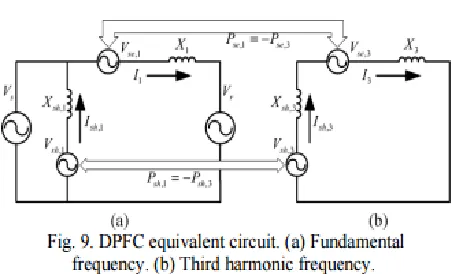
3.ANALYSIS OF THE DPFC
In this section, the consistent-state behaviour
of the DPFC is analyzed, and the control
capability of the DPFC is expressed within
the parameters of the community and the
DPFC. To simplify the DPFC, the
converters are changed by controllable
voltage sources in series with impedance.
Considering the fact that every converter
generates the voltage at two distinct
frequencies, it's represented through two
series-related controllable voltage sources,
one at the predominant frequency and the
opposite on the 1/3-harmonic frequency.
Assuming that the converters and the
transmission line are lossless, the total lively
vigor generated by means of the 2 frequency
voltage sources will be zero. The more than
one sequence converters are simplified as
one massive converter with the voltage,
which is the same as the sum of the voltages
for all sequence converter, as proven, the
DPFC is placed in a two-bus system with the
sending-end and the receiving-finish
voltages Vs and Vr , respectively. The
transmission line is represented by using an
inductance L with the line current I. The
voltage injected through all the DPFC series
converters is Vse,1 and Vse,3 at the
essential and the 1/3-harmonic frequency,
respectively. The shunt converter is attached
to the sending bus by way of the inductor
Lsh and generates the voltage Vsh,1 and
Vsh,three ; the current injected through the
shunt converter is Ish . The lively and
reactive energy go with the flow at the
receiving finish is Pr and Qr , respectively.
This illustration consists of each the main
and 0.33-harmonic frequency add-ons.
Headquartered on the superposition
theorem, the circuit in Fig. Eight may also
be extra simplified through being break up
into two circuits at one of a kind
frequencies. The two circuits are remoted
from each different, and the hyperlink
stability of every converter, as proven in
Fig.
4.Central Control
The central control generates the reference
signals for both the shunt and series
converters of the DPFC. It is aimed on the
DPFC tasks at the power-system level, such
as power-flow control, low-frequency power
oscillation damping, and balancing of
asymmetrical components. According to the
system requirement, the central control gives
corresponding voltage-reference signals for
the series converters and reactive current
signal for the shunt converter. All the
reference signals generated by the central
control are at the fundamental frequency.
4.1. Series Control
Every single series converter has its own
series control. The controller is used to
maintain the capacitor dc voltage of its own
converter by using the thirdharmonic
frequency components and to generate series
voltage at the fundamental frequency that is
given by the central control loop with the
DPFC series converter control. The principle
of the vector control is used here for the
dc-voltage control [7]. The third-harmonic
current through the line is selected as the
rotation reference frame for the single-phase
park transformation, because it is easy to be
captured by the phase-locked loop (PLL) [8]
in the series converter.
4.2. Shunt Control
The block diagram of the shunt converter
control . The objective of the shunt control
is to inject a constant third harmonic current
into the line to provide active power for the
series converters. The third-harmonic
current is locked with the bus voltage at the
fundamental frequency. A PLL is used to
capture the bus-voltage frequency, and the
output phase signal of the PLL is multiplied
by three to create a virtual rotation reference
frame for the third-harmonic component.
The control for the fundamental frequency
components consists of two cascaded
controllers. The current control is the inner
control loop, which is to modulate the shunt
current at the fundamental frequency. The
q-component of the reference signal of the
shunt converter is obtained from the central
the dc control. The shunt converter’s
fundamental frequency control aims to inject
a controllable reactive current to grid and to
keep the capacitor dc voltage at a constant
level.
5.DPFC Advantages and Applications
The DPFC can be viewed as a UPFC which
uses the D-FACTS concept and the concept
of exchanging power through harmonic.
Therefore, the DPFC inherits all the
advantages of the UPFC and the D-FACTS,
which are as follows.
5.1 High control capability. The DPFC can
simultaneously control all the parameters of
the
power system: the line impedance, the
transmission angle, and the bus voltage. The
elimination of the common dc link enables
separated installation of the DPFC
converters. The shunt and series converters
can be placed at the most effectively
location. Due to the high control capability,
the DPFC can also be used to improve the
power quality and system stability, such as
low-frequency power oscillation damping
[9], voltage sag restoration [10], or
balancing asymmetry.
5.2 High reliability. The redundancy of the
series converter gives an improved
reliability. In
addition, the shunt and series converters are
independent, and the failure at one place will
not influence the other converters. When a
failure occurs in the series converter, the
converter will be short-circuited by bypass
protection, thereby having little influence to
the network. In the case
of the shunt converter failure, the shunt
converter will trip and the series converter
will stop providing active compensation and
will act as the D-FACTS controller [11].
5.3 Low cost. There is no phase-to-phase
voltage isolation required by the series
converter. Also, the power rating of each
converter is small and can be easily
produced in series production lines.
When the DPFC is applied in power
systems, the reliability issue is important.
The fault tolerance of the DPFC is
investigated, including the protection
method for different types of failures and the
use of supplementary controls, to improve
system performance during converter
failures. Two control modes are predefined
for each series converter, namely
full-control mode and limited-full-control mode. In
normal situations, the series converters
operate in the fullcontrol mode, which uses
the 3rd harmonic component to maintain the
failure, the 3rd harmonic current cannot be
injected and the series converter will operate
in the control mode. In the
limited-control mode, the series converter uses the
active power at the fundamental frequency
to stabilize the DC voltage. It is also capable
of controlling the reactive power injection at
the fundamental frequency. Due to the
over-voltage protection, during a failure, the
series converter appears as a short circuit to
transmission lines. Accordingly, the network
becomes asymmetric during the failure of a
series converter because of the asymmetrical
voltage injection. To compensate for this
asymmetry, a supplementary control is
applied to the central controller. The
controller monitors the voltages at the
sending and receiving ends and the line
current, to calculate the total voltage
injected by all series converters. By
comparing this calculated voltage and the
reference voltage generated by the central
control, the operation status of the series
converters is known. According to the
operation status, the controller can
automatically adjust the reference for each
series converter [12]. The two
supplementary controls are verified both in
Matlab Simulink and in the experimental
setup. This
proves that the supplementary controls can
improve DPFC performance during
converter failures and therefore, the DPFC
have relatively high reliability [13]. DPFC
can compensate both negative and zero
sequence components, consequently the
DPFC is more powerful than other FACTS
device for compensation of unbalanced
currents. Additional controllers are
supplemented to existing DPFC controller,
and their principle is to monitor the negative
and zero sequences of the current through
the transmission line, and to force them to
be zero by applying an opposing voltage
[14].
6. CONCLUSION
In this paper, the essential features of DPFC
controller with various applications were
discussed. The potential to enhancement of
power system stability as well as reliability
of power system was explained. In power
system transmission, it is required to
maintain thevoltage magnitude, phase angle
and line impedance. Consequently, to
control power flow over designated
transmission line and enhancement of power
system stability FACTS devices are used in
modern power system network. In this
review paper the role of DPFC device in
power system network are addressed.
Therefore, the following results are found,
power flow control is achieved by using
FACTS (DPFC) devices and transient
stability is improved and faster steady state
is achieved. Hence congestion is less by
improving transient stability and reliability.
By using different control strategies,
performance of DPFC can be further
modified as per the requirement.
REFERENCES
[1] Y.-H. Song and A. Johns, Flexible ac
Transmission Systems (FACTS) (IEE Power
and Energy Series), vol. 30. London, U.K.:
Institution of Electrical Engineers, 1999.
[2] Deepak Divan and Harjeet Johal
"Distributed FACTS-A New Concept for
Realizing Grid Power Flow Control", IEEE
Transactions on Power Electronics, Vol. 22,
No. 6, November 2007.
[3] L. Gyugyi, C. D. Schauder, S. L.
Williams, T. R. Rietman, D. R. Torgerson,
and A. Edris. “The unified power flow
controller: a new approach to power
transmission control”. Power Delivery,
IEEE Transactions on, 1995.
[4] K. K. Sen, “Sssc-static synchronous
series compensator: Theory, modeling, and
application,” IEEE Trans. Power Del., vol.
13, no. 1, pp. 241–246, Jan. 1998.
[5] D. Divan, W. Brumsickle, R. Schneider,
B. Kranz, R. Gascoigne, D. Bradshaw, M.
Ingram, and I. Grant, “A Distributed Static
Series Compensator System for Realizing
Active Power Flow Control on Existing
Power Lines,” IEEE Trans. Power Del., Vo
22, Issue 1, pp. 642 - 649 Jan. 2007.
[6] Zhihui Yuan,Sjoerd W.H.de Haan,Jan
Braham Ferreira,Dalibor Cvoric”A FACTS
Device:Distributed Power Flow
Controller(DPFC)’’ IEEE Transactions
Power Electronics, vol. 25, no.10,
,pp.2564-2572,October 2010.
[7] Y. Sozer and D. A. Torrey, “Modeling
and control of utility interactive inverters,”
IEEE Trans. Power Electron., vol. 24, no.
11, pp. 2475–2483, Nov. 2009.
[8] L. Huber, B. T. Irving, and M. M.
Jovanovic, “Review and stability analysis of
pll-based interleaving control of dcm/ccm
boundary boost pfc converters,” IEEE
Trans. Power Electron., vol. 24, no. 8, pp.
1992–1999, Aug. 2009.
[9] Y. Zhihui, S.W. H. de Haan, and B.
Ferreira, “Utilizing distributed power flow
controller (dpfc) for power oscillation
damping,” in Proc. IEEE Power Energy Soc.
Gen. Meet. (PES), 2009, pp. 1–5.
[10] Ahmad Jamshidi, S. Masoud Barakati,
Distributed Power Flow Controller to
Improve Power Quality Based on
Synchronous Reference Frame Method,”
IACSIT International Journal of Engineering
and Technology, Vol. 4, No. 5, October
2012
[11] Y. Zhihui, S. W. H. de Haan, and B.
Ferreira, “Dpfc control during shunt converter failure,” in Proc. IEEE Energy
Convers. Congr. Expo. (ECCE), 2009, pp.
2727–2732.
[12] Yuan, Z.; de Haan, S.W.H.; Ferreira,
B.: “Control Scheme to Improve DPFC
Performance during Series Converter
Failures”, IEEE Power and Energy Society
General Meeting (PESGM) 2010,
Minneapolis, USA.
[13] K.Ramya; Dr.C.Christober Asir Rajan:
“Analysis and Regulation of System
Parameters using DPFC”, IEEE -
International Conference On Advances In
Engineering, Science And Management
(ICAESM -2012) March 30, 31, 2012
[14] Yuan, Z.; de Haan, S.W.H.; Ferreira,
B.; Cvoric, D.: “Utilize Distributed Power
Flow Controller (DPFC) to Compensate
Unbalanced 3-phase Currents in
Trans-missions Systems”, Electric Power and
Energy Conversion Systems (EPECS) 2009,