Enhancing the Power quality in distribution system
using 11 level inverter
K. Srilatha (roll number 14n81d4310) & Guide name:Sayed Abdul
Mail id [email protected]
Spoorthi Engineering Eollege
Abstract— In this paper, a new single-phase wind energy inverter (WEI) with flexible AC transmission system (FACTS) capability is presented. The proposed inverter is placed between the wind turbine and the grid, same as a regular WEI, and is able to regulate active and reactive power transferred to the grid. This inverter is equipped with distribution static synchronous compensators option in order to control the power factor (PF) of the local feeder lines. Using the proposed inverter for small-to-medium-size wind applications will eliminate the use of capacitor banks as well as FACTS devices to control the PF of the distribution lines. The goal of this paper is to introduce new ways to increase the penetration of renewable energy systems into the distribution systems. This will encourage the utilities and customers to act not only as a consumer, but also as a supplier of energy. Moreover, using the new types of converters with FACTS capabilities will significantly reduce the total cost of the renewable energy application. In this paper, modular multilevel converter is used as the desired topology to meet all the requirements of a single-phase system such as compatibility with IEEE standards, total harmonic distortion (THD), efficiency, and total cost of the system. The proposed control strategy regulates the active and reactive power using power angle and modulation index, respectively. The function of the proposed inverter is to transfer active power to the grid as well as keeping the PF of the local power lines constant at a target PF regardless of the incoming active power from the wind turbine. The simulations for an 11-level inverter have been done in MATLAB/Simulink. To validate the simulation results, a scaled prototype model of the proposed inverter has been built and tested.
Index Terms— Modular multilevel converter (MMC), multilevel inverter (MLI), wind energy inverter (WEI).
I. INTRODUCTION
T
HE ROLE of power electronics in distribution systems has greatly increased recently. The power electronicdevices are usually used to convert the nonconventional forms of energy to the suitable energy for power grids, in terms of voltage and frequency. In permanent magnet (PM) wind applications, a back-to-back converter is normally utilized to connect the generator to the grid. A rectifier equipped with a maximum power point tracker (MPPT), converts the output power of the wind turbine to a dc power. The dc power is then converted to the desired ac power for power lines using an inverter and a transformer. With
recent developments in wind energy, utilizing smarter wind energy inverters (WEIs) has become an important issue. There are a lot of single-phase lines in the United States, which power small farms or remote houses [1], [2]. Such customers have the potential to produce their required energy using a small-to-medium-size wind turbine. Increasing the number of small-to-medium wind turbines will make several troubles for local utilities such as harmonics or power factor (PF) issues.
A high PF is generally desirable in a power system to decrease power losses and improve voltage regulation at the load. It is often desirable to adjust the PF of a system to near 1.0. When reactive elements supply or absorb reactive power near the load, the apparent power is reduced. In other words, the current drawn by the load is reduced, which decreases the power losses. Therefore, the voltage regulation is improved if the reactive power compensation is performed near large loads. Traditionally, utilities have to use capacitor banks to compensate the PF issues, which will increase the total cost of the system. The modern ways of controlling the PF of these power lines is to use small distribution static synchronous com-pensators (D-STATCOMs). The D-STATCOMs are normally placed in parallel with the distributed generation systems as well as the power systems to operate as a source or sink of reactive power to increase the power quality issues of the power lines. Using regular STATCOMs for small-to-medium-size single-phase wind applications does not make economic sense and increase the cost of the system significantly. This is where the idea of using smarter WEIs with FACTS capabilities shows itself as a new idea to meet the targets of being cost-effective as well as compatible with IEEE standards. The proposed inverter in this paper is equipped with a D-STATCOM option to regulate the reactive power of the local distribution lines and can be placed between the wind turbine and the grid, same as a regular WEI without any additional cost. The function of the proposed inverter is not only to convert dc power coming from dc link to a suitable ac power for the main grid, but also to fix the PF of the local grid at a target PF by injecting enough reactive power to the grid. In the proposed control strategy, the concepts of the inverter and the D-STATCOM have been combined to make a new inverter, which possesses FACTS capability with no additional cost. The proposed control strategy allows the inverter to act as an inverter with D-STATCOM option when there is enough wind to produce active power, and to act as a D-STATCOM when there is no wind. The active power is controlled by adjusting
International Journal of Research
Available at https://edupediapublications.org/journals
p-I SSN: 2 3 4 8 -6 8 4 8 e-I SSN: 2 3 4 8 -7 9 5 X Vol ume 0 4 I s s ue 0 2
Febr ua r y 2 0 1 7
Available online: https://edupediapublications.org/journals/index.php/IJR/ P a g e | 5 9
Available online: Available online: https://edupediapublications.org/journals/index.php/IJR/https://edupediapublications.org/journals/index.php/IJR/ P a g eP a g e | 5 9 | 5 9
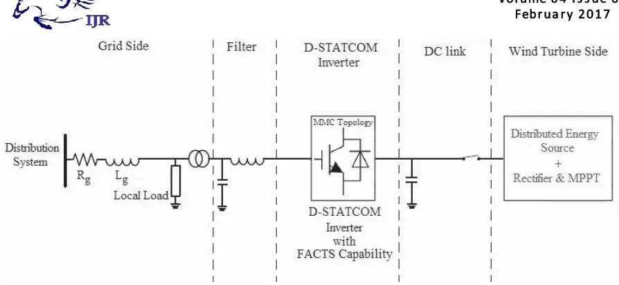
Fig. 1. Complete configuration of the proposed inverter with FACTS capability.
the power angle δ, which is the angle between the voltages of the inverter and the grid, and reactive power is regulated by the modulation index m.
There are a large number of publications on integration of renewable energy systems into power systems. A list of com-plete publications on FACTS applications for grid integration of wind and solar energy was presented in [3]. In [4], new commercial wind energy converters with FACTS capabilities are introduced without any detailed information regarding the efficiency or the topology used for the converters. In [5], a complete list of the most important multilevel inverters was reviewed. Also, different modulation methods such as sinusoidal pulsewidth modulation (PWM), selective harmonic elimination, optimized harmonic stepped waveform tech-nique, and space vector modulation were discussed and com-pared. Among all multilevel topologies [6]–[9], the cascaded H-bridge multilevel converter is very well known for STATCOM applications for several reasons [10]–[12]. The main reason is that it is simple to obtain a high number of levels, which can help to connect STATCOM directly to medium voltage grids. The modular multilevel converter (MMC) was introduced in the early 2000s [13], [14]. Refer-ence [15] describes a MMC converter for high voltage DC (HVDC) applications. This paper mostly looks at the main circuit components. Also, it compares two different types of MMC, including H-bridge and full-bridge submodules. In [9] and [16], a new single-phase inverter using hybrid-clamped topology for renewable energy systems is presented. The proposed inverter is placed between the renewable energy source and the main grid. The main drawback of the proposed inverter is that the output current has significant fluctuations that are not compatible with IEEE standards. The authors believe that the problem is related to the snubber circuit design. Several other applications of custom power electronics in renewable energy systems exist, including [17] an application of a custom power interface where two modes of operation, including an active power filter and a renewable energy STATCOM. Another application [18] looks at the current-source inverter, which controls reactive power and regulates voltage at the point of common coupling (PCC). Varma et al.
[19], [20] propose an application of photovoltaic (PV) solar inverter as STATCOM in order to regulate voltage on three-phase power systems, for improving transient stability and power transfer limit in transmission systems. The authors called their proposed system PV-STATCOM. Similar to wind farms (when there is no wind), solar farms are idle during nights. We proposed a control strategy that makes the solar farms to act as STATCOMs during night when they are not able to produce active power. The main purpose of the PV-STATCOM system is to improve the voltage control and the PF correction on three-phase transmission systems.
In this paper, the proposed WEI utilizes MMC topology, which has been introduced recently for HVDC applications. Replacing conventional inverters with this inverter will elimi-nate the need to use a separate capacitor bank or a STATCOM device to fix the PF of the local distribution grids. Obviously, depending on the size of the power system, multiple inverters might be used in order to reach the desired PF. The unique work in this paper is the use of MMC topology for a single-phase voltage-source inverter, which meets the IEEE standard 519 requirements, and is able to control the PF of the grid regardless of the wind speed Fig. 1 shows the complete grid-connected mode configuration of the proposed inverter. The dc link of the inverter is connected to the wind turbine through a rectifier using MPPT and its output terminal is connected to the utility grid through a series-connected second-order filter and a distribution transformer.
II. MODULARMULTILEVELCONVERTER
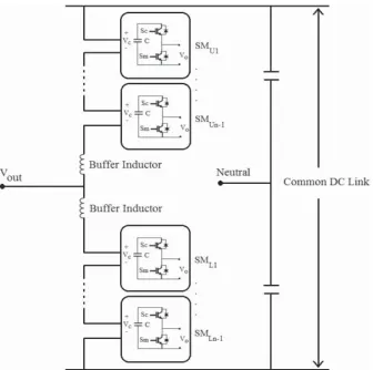
Fig. 2. Structure of a single-phase MMC inverter structure.
applications such as wind energy applications. Moreover, this topology needs only one dc source, which is a key point for wind applications. MMC requires large capacitors which may increase the cost of the systems; however, this problem is offset by the lack of need for any snubber circuit.
The main benefits of the MMC topology are: modular design based on identical converter cells, simple voltage scaling by a series connection of cells, simple realization of redundancy, and possibility of a common dc bus. Fig. 2 shows the circuit configuration of a single-phase MMC and the structure of its SMs consisting of two power switches and a floating capacitor.
The output voltage of each SM (vo) is either equal to its
capacitor voltage (vc) or zero, depending on the switching
states. The buffer inductors must provide current control in each phase arm and limit the fault currents. To describe the operation of MMC, each SM can be considered as a two-pole switch. If Sui, which is defined as the status of the
i th submodule in the upper arm, is equal to unity, then the
output of the ith SM is equal to the corresponding capacitor voltage; otherwise it is zero. Likewise, if Sli which is defined
as the status of the i th submodule in the lower arm, is equal to unity, then the output of the i th lower SM is equal to the corresponding capacitor voltage; otherwise it is zero. Generally, when Sui or Sli is equal to unity, the i th upper or
lower SM isON; otherwise it isOFF. Therefore, the upper and
lower arm voltages of the MMC are as follows:
vupperArm=
n−1
i=1
(Suivci)+v11 (1)
vlowerArm=
n−1
i=1
(Slivci)+v12 (2)
where v11 and v12 are the voltages of the upper and lower
buffer inductors, n is the number of voltage levels, and vci is
the voltage of the i th SMs capacitor in upper arm or lower arm. A single-phase 11-level MMC inverter consists of 20 SMs which translates to 40 power switches, 20 capacitors, and 2 buffer inductors. The dc and ac voltages of the 11-level MMC are described by
vDC =vupperArm+vlowerArm
=
10
i=1
(Suivci)+ 10
i=1
(Suivci)+(v11+v12) (3)
vout =
vDC
2 −vupperArm= −
vDC
2 +vlowerArm. (4)
III. PROPOSEDCONTROLSTRATEGY
The proposed controller consists of three major functions. The first function is to control the active and reactive power
International Journal of Research
Available at https://edupediapublications.org/journals
p-I SSN: 2 3 4 8 -6 8 4 8 e-I SSN: 2 3 4 8 -7 9 5 X Vol ume 0 4 I s s ue 0 2
Fig. 3. Schematic of the proposed controller system.
transferred to the power lines, the second function is to keep the voltages of the SMs’ capacitors balanced, and the third function is to generate desired PWM signals. Fig. 3 shows the complete proposed controller system.
The aim of the designed inverter is to transfer active power coming from the wind turbine as well as to provide utilities with distributive control of volt-ampere reactive (VAR) com-pensation and PF correction of feeder lines. The application of the proposed inverter requires active and reactive power to be controlled fully independent, so that if wind is blowing, the device should be working as a normal inverter plus being able to fix the PF of the local grid at a target PF (D-STATCOM option), and if there is no wind, the device should be only operating as a D-STATCOM (or capacitor bank) to regulate PF of the local grid. This translates to two modes of operation: 1) when wind is blowing and active power is coming from the wind turbine: the inverter plus D-STATCOM mode. In this mode, the device is working as a regular inverter to transfer active power from the renewable energy source to the grid as well as working as a normal D-STATCOM to regulate the reactive power of the grid in order to control the PF of the grid and 2) when wind speed is zero or too low to generate active power: the D-STATCOM mode. In this case, the inverter is acting only as a source of reactive power to control the PF of the grid, as a D-STATCOM. This option eliminates the use of additional capacitor banks or external STATCOMs to regulate the PF of the distribution feeder lines. Obviously, the device is capable of outputting up to its rated maximum real power and/or reactive power, and will always output all real power generated by the wind turbine to the grid. The amount of reactive power, up to the design maximum, is dependent only on what the utility asks the device to produce.
Generally, (5) and (6) dictate the power flow between a STATCOM device and power lines
PS = −ESEL
X sinδ (5)
QS = −ESELcosδ−E
2
L
X (6)
where X is the inductance between the STATCOM (here as
inverter) and the grid which is normally considered as output filter inductance added to the transmission line inductance. The root mean square (RMS) voltage of the STATCOM (= inverter) is given as Es and is considered to be out of phase
by an angle ofδ to the RMS line voltage E1.
In the proposed control strategy, active and reactive power transferred between the inverter and the distribution grid is controlled by selecting both the voltage level of the inverter and the angle δ between the voltages of inverter and grid, respectively. The amplitude of the inverter voltage is regulated by changing the modulation index m and the angleδby adding a delay to the firing signals which concludes
PS = −m ESEL
X sinδ (7)
QS = −m ESELcosδ−E
2
L
X . (8)
In this paper, m is the key factor to control the reactive power compensation and its main task is to make the PF of the grid equal to the target PF. δ is the control parameter to adjust the active power control between the inverter and the grid.
Several assumptions should be considered for the proposed controller which are as: 1) the load on the feeder line should be considered fixed for a small window of time and there is no change in the load during a cycle of the grid frequency; 2) the feeder line can be accurately modeled as a constant P,
Q load. This means that the power produced by a wind turbine
will displace other power on the feeder line and not add to it; and 3) although making a change in m orδ has effect on both (7) and (8), it is assumed that a change in the modulation index will predominantly affect Q, while a change in delta will predominantly affect P. Any effect on Q from a small change in delta is thus ignored. This results in controlling P and Q independently. Equation (9) shows the relation between the target reactive power and the target PF
PG =
PG2+Q2T
×PFT (9)
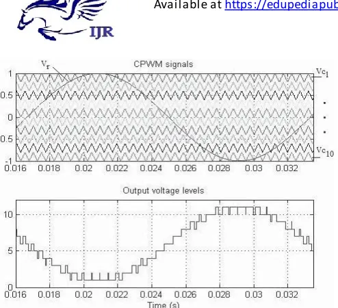
Fig. 4. CPWM waveforms for an11-level MMC inverter, and the generated output voltage levels.
the target amount of reactive power, and PFT is the target
PF desired by the utility. So, QT can be calculated as
QT =
PG
PFT
2
−P2
G. (10)
Using (9) and (10), the target reactive power for the grid is determined and is compared with the actual value of the reac-tive power of the grid. Using a PI compensator will determine the desired value for the modulation index. The power angle is also determined by comparing the actual dc voltage of the inverter with a reference value. A PI compensator determines the desired value for the power angle.
The second function of the controller systems is to keep the capacitors’ voltages balanced. In order to do this, a carrier-based pulsewidth modulation (CPWM) method [25], [26] is used. The top graph in Fig. 4 shows the reference signal and the carrier waveforms for an 11-level MMC inverter using CPWM technique. The bottom graph of Fig. 4 shows the output voltage levels generated based on Table I.
In an 11-level CPWM technique, ten carrier signals are compared with a reference sinusoidal signal. In Fig 4, based on the phase of the reference signal(vr), there are 11 operating regions where each region defines a voltage level in the output
nupperArm+nlowerArm=10 (11)
where nupperArmand nlowerArmare the numbers of SMs which
are ON (Sc isON and Sm is OFFin Fig. 1) in the upper arm
or lower arm, respectively.
In an 11-level MMC inverter, there are ten upper and ten lower SMs where each SM has a capacitor. For instance, in voltage level 1 of Table I, all the upper SMs should be
OFFand all the lower SMs should beON, which translates to the fact that the main switches Sm of all upper SMs and the
auxiliary switches (Sc)of all lower SMs have to be ON and
all the other switches have to be OFF. In this case, the input dc voltage is applied only to the ten lower capacitors, so that
TABLEI
OPERATINGREGIONSFORAN11-LEVELMMCINVERTER
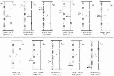
the output voltage is vDC/2. Fig. 5 illustrates the selection of
capacitors for different voltage levels shown in Table I. The most critical issue to control MMC is to maintain the voltage balance across all the capacitors. Therefore, the SMs’ voltages are measured and sorted in descending order during each cycle. If the current flowing through the switches is positive, so that capacitors are being charged, nupperArm
and nupperArm and of the SMs in upper arm and lower arm
with the lowest voltages are selected, respectively. As a result, ten capacitors with lowest voltages are chosen to be charged. Likewise, if the current flowing through the switches is negative, so that capacitors are being discharged, nupperArm
and nupperArm of the SMs in upper arm and lower arm
with highest voltages are selected, respectively. As a result, ten capacitors with highest voltages are chosen to be dis-charged. Consequently, the voltages of the SMs’ capaci-tors are balanced. Considering Table I and based on the direction of the current flowing through the switches, the proper algorithm will be selected to maintain capacitor balance.
The third function of the controller system is the PWM generation block. In this block, based on the desired modulation index, power angle, voltages of the capacitors, direction of the current flowing through the switches and using Table I, the controller generates the PWM signals in order to meet all the system requirements.
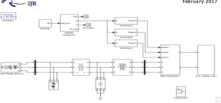
IV. SIMULATION ANDPRACTICALRESULTS
The design of an 11-level MMC inverter was carried out in MATLAB/Simulink. The simulation is 20 s long and contains
International Journal of Research
Available at https://edupediapublications.org/journals
p-I SSN: 2 3 4 8 -6 8 4 8 e-I SSN: 2 3 4 8 -7 9 5 X Vol ume 0 4 I s s ue 0 2
Fig. 5. Selection of SMs’ capacitors for different voltage levels.
TABLE II
PARAMETERSUSED FOR THESIMULATION
severe ramping and de-ramping of the wind turbine. The goal is to assess the behavior of the control system in the worst conditions. Table II shows the values of the parameters used for the simulation.
Before t =6 s, there is no wind to power the wind turbine; therefore, the dc link is open-circuited. At t =6 s, the input
Fig. 6. Simulated output active power from the wind turbine.
Fig. 7. Simulated active and reactive power of the inverter (top graph), active and reactive power of the power lines (bottom graph).
Fig. 8. Simulated output voltage of an 11-level inverter.
from the wind turbine and the grid. After t =6 s, the output power of the wind turbine is increased, and as a result the level of active power provided by the feeder line is decreased by the same amount. The simulated output voltage of the inverter before the filter is shown in Fig. 8. Fig. 9 shows the PF of the grid. The PF of the grid is constant at 0.90 regardless of the active power from the wind turbine, showing that the main goal of the inverter is achieved. The set-point for dc link voltage of the inverter is 2000 V and the RMS value of the output ac voltage is 600 V. The delta and modulation index graphs are shown in Fig. 10. As soon as the active power comes from the wind turbine, the controller system increases the value of the power angle in order to output more active power to the grid. Therefore, the active power provided from the feeder lines to the load is decreased, and as a result the reactive power from the feeder lines is decreased. Consequently, the modulation index is increased by the controller system to inject more reactive power needed by the load.
Fig. 9. Simulated PF of the grid.
Fig. 10. Simulated delta and modulation index of the 11-level inverter.
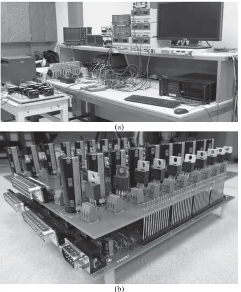
To validate the simulation results, a scaled version of the proposed inverter has been built and tested. The power rating of the scaled prototype model is 250 W and/or VAR, which is limited by the rating of the semiconductor devices. The experimental results serve only as a proof-of-concept. In order to implement the control strategy and to handle the feedback signals, two CLP 1104 dSPACE systems have been synchro-nized. A three-phase PM generator driven by a variable speed dc motor is used to emulate the wind speed change. Fig. 11 shows the test bench setup and the 11-level prototype inverter. Fig. 12 shows the output voltage of the inverter where the switching frequency and the values of the LC filter is 2 kHz, 5 mH, and 10μF, respectively. The efficiency of the inverter is close to 0.95. The experimental output voltage THD and current TDD is 2.7 and 2.12%, respectively.
In grid-connected mode, the inverter is connected to the grid through a transformer with the ratio 120:24. The load
International Journal of Research
Available at https://edupediapublications.org/journals
p-I SSN: 2 3 4 8 -6 8 4 8 e-I SSN: 2 3 4 8 -7 9 5 X Vol ume 0 4 I s s ue 0 2
Fig. 11. (a) Test bench setup. (b) Scaled prototype model of the proposed 11-level inverter.
Fig. 12. Output voltage of the proposed 11-level inverter.
PF is set to 0.65 and the target PF is 0.90. In this case, the job of the inverter is to fix the PF at the target PF regardless of the input active power from the wind emulator. In order to show the performance of the system conveniently, an AEMC 8230 power meter is used and the practical results are captured and shown using and the ControlDesk, which is a helpful tool associated with the dSPACE 1104 package. Fig. 13 shows the system parameters before compensation in which the inverter is disconnected from the grid. In this case the inverter is open-circuited and there is no active or reactive power transfer between the inverter and the wind emulator.
Fig. 13. Grid parameters before compensation where the compensator is disconnected from the grid. (a) Voltage and current. (b) Active power, reactive power, and PF.
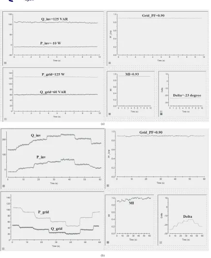
Fig. 14(a) shows the system parameters after compensation when there is no active power coming from the wind emulator. In this case, the inverter acts as a D-STATCOM to improve the PF of the grid. Ideally, there should be no active power transfer between the two sources, but due to the nonideality of the components and to charge the capacitors, 10 W is drawn from the grid. As it can be seen, the compensated PF of the local grid is constant at 0.90: the inverter is performing properly as a D-STATCOM. Fig. 14(b) shows the system parameters after compensation when there is active power from the wind emulator. In this case, the inverter is acting as an inverter with PF correction capability and the PF of the local grid is fixed at 0.90 with small oscillations. Figs. 13 and 14 show that the grid PF before compensation is 0.65 and after the compensation is constant at the target PF, which is 0.90 in this case, regardless of the input active power from the wind emulator. The amount of active power which is drawn from the grid changes with the amount of incoming active power from the wind emulator. When the output power of the wind turbine is increased, the level of active power provided by the feeder line is decreased by the same amount.
Fig. 14. System parameters where the inverter is connected to the grid. (a) When wind speed is zero and there is no active power coming from wind emulator. (b) When wind speed is changing and the incoming active power from the wind emulator is changing.
in order to decrease the dc link voltage. The modulation index m is also increased when the inverter is supposed to inject more reactive power to the grid. The transient response of the PI controllers used to control the modulation index and delta can be adjusted by changing the proportional and integral coefficients of the controllers. The practical results show that the performance of the proposed controller strategy is sufficiently close to the simulation results. The PI controllers
show a proper performance during severe changes in the wind speed, which is emulated by the wind emulator.
V. CONCLUSION
In this paper, the concept of a new multilevel inverter with FACTS capability for small-to-mid-size wind installations is presented. The proposed system demonstrates the application of a new inverter with FACTS capability in a single unit
International Journal of Research
Available at https://edupediapublications.org/journals
p-I SSN: 2 3 4 8 -6 8 4 8 e-I SSN: 2 3 4 8 -7 9 5 X Vol ume 0 4 I s s ue 0 2
without any additional cost. Replacing the traditional renew-able energy inverters with the proposed inverter will eliminate the need of any external STATCOM devices to regulate the PF of the grid. Clearly, depending on the size of the compensation, multiple inverters may be needed to reach the desired PF. This shows a new way in which distributed renewable sources can be used to provide control and support in distribution systems. The proposed controller system adjusts the active power by changing the power angle (delta) and the reactive power is controllable by the modulation index m. The simulation results for an 11-level inverter are presented in MATLAB/Simulink. To validate the simulation results, a scaled prototype of the proposed 11-level inverter with D-STATCOM capability is built and tested. Practical results show good performance of the proposed control strategy even in severe conditions.
REFERENCES
[1] U.S. Solar Market Insight, 2010 Year End Review Executive Summary, SEIA, Washington, DC, USA, 2011.
[2] AWEA U.S. Wind Industry Annual Market Report Year Ending 2010, AWEA, Washington, DC, USA, 2011.
[3] S. A. Rahman, R. K. Varma, and W. H. Litzenberger, “Bibliography of FACTS applications for grid integration of wind and PV solar power systems: 1995–2010 IEEE working group report,” in Proc. IEEE Power
Energy Soc. General Meeting, Jul. 2011, pp. 1–17.
[4] A. Beekmann, J. Marques, E. Quitmann, and S. Wachtel, “Wind energy converters with FACTS capabilities for optimized integration of wind power into transmission and distribution systems,” in Proc. CIGRE/IEEE
PES Joint Symp. Integr. Wide, Scale Renew. Resour. Power Del. Syst.,
Jul. 2009, pp. 1–9.
[5] J. Rodriguez, J. S. Lai, and F. Z. Peng, “Multilevel inverters: Survey of topologies, controls, and applications,” IEEE Trans. Ind. Appl., vol. 49, no. 4, pp. 724–738, Aug. 2002.
[6] F. Z. Peng, J. S. Lai, J. W. McKeever, and J. VanCoevering, “A mul-tilevel voltage-source inverter with separate DC sources for static VAr generation,” IEEE Trans. Ind. Appl., vol. 32, no. 5, pp. 1130–1138, Oct. 1996.
[7] L. M. Tolbert and F. Z. Peng, “Multilevel converters as a utility interface for renewable energy systems,” in Proc. IEEE Power Eng. Soc. Summer
Meeting, vol. 2. Jul. 2000, pp. 1271–1274.
[8] S. Kouro, M. Malinowski, K. Gopakumar, J. Pou, L. G. Franquelo, B. Wu, et al., “Recent advances and industrial applications of multilevel converters,” IEEE Trans. Ind. Electron., vol. 57, no. 8, pp. 2553–2580, Aug. 2010.
[9] C. Tareila, P. Sotoodeh, and R. D. Miller, “Design and control of a single-phase D-STATCOM inverter for wind application,” in Proc.
PEMWA, Jul. 2012, pp. 1–5.
[10] B. Gultekin and M. Ermis, “Cascaded multilevel converter-based trans-mission STATCOM: System design methodology and development of a 12 kV±12 MVAr power stage,” IEEE Trans. Power Electron., vol. 28, no. 11, pp. 4930–4950, Nov. 2013.
[11] K. Sano and M. Takasaki, “A transformerless D-STATCOM based on a multivoltage cascade converter requiring no DC sources,”
IEEE Trans. Power Electron., vol. 27, no. 6, pp. 2783–2795,
Jun. 2012.
[12] X. Liang, Y. Xu, X. Chen, and C. Guo, “The simulation research of STATCOM based on cascaded multi-level converter,” in Proc. 4th Int.
Conf. Electr. Util. DRPT, Jul. 2011, pp. 494–498.
[13] M. Davies, M. Dommaschk, J. Dorn, J. Lang, D. Retzmann, and D. Soerangr, HVDC PLUS Basic and Principle of Operation. Erlandgen, Germany: Siemens AG Energy Sector, 2009.
[14] B. Gemmell, J. Dorn, D. Retzmann, and D. Soerangr, “Prospects of multilevel VSC technologies for power transmission,” in Proc. IEEE
Transmiss. Distrib. Conf. Exposit., Apr. 2008, pp. 1–16.
[15] C. D. Barker and N. M. Kirby, “Reactive power loading of components within a modular multi-level HVDC VSC converter,” in Proc. IEEE
EPEC, Oct. 2011, pp. 86–90.
[16] C. P. Tareila, “A single-phase D-STATCOM Inverter for distributed energy sources,” M.S. thesis, Dept. Electr. Comput. Eng., Kansas State Univ., Manhattan, KS, USA, Aug. 2011.
[17] Z. Yang, C. Shen, L. Zhang, M. L. Crow, and S. Atcitty, “Integration of a STATCOM and battery energy storage,” IEEE Trans. Power Syst., vol. 16, no. 2, pp. 254–260, May 2001.
[18] S. Chakraborty, B. Kroposki, and W. Kramer, “Evaluation of control and voltage regulation functionalities in a single-phase utility-connected inverter for distributed energy applications,” in Proc. IEEE ECCE, Sep. 2009, pp. 1753–1759.
[19] R. K. Varma, S. A. Rahman, A. C. Mahendra, R. Seethapathy, and T. Vanderheide, “Novel nighttime application of PV solar farms as STATCOM (PV-STATCOM),” in Proc. IEEE Power Energy Soc.
Gen-eral Meeting, Jul. 2012, pp. 1–8.
[20] R. K. Varma, E. M. Siavashi, B. Das, and V. Sharma, “Real-time digital simulation of a PV solar system as STATCOM (PV-STATCOM) for voltage regulation and power factor correction,” in Proc. EPEC, Oct. 2012, pp. 157–163.
[21] R. K. Varma, S. A. Rahman, V. Sharma, and T. Vanderheide, “Novel control of a PV solar system as STATCOM (PV-STATCOM) for pre-venting instability of induction motor load,” in Proc. 25th IEEE CCECE, May 2012, pp. 1–5.
[22] R. Marquardt and A. Lesnicar, “New concept for high voltage—Modular multilevel converter,” in Proc. PESC, Jun. 2004, pp. 1–5.
[23] A. Lesnicar and R. Marquardt, “An innovative modular multilevel converter topology suitable for a wide power range,” in Proc. IEEE
Power Tech. Conf., vol. 3. Jun. 2003, pp. 1–6.
[24] M. Saeedifard and R. Iravani, “Dynamic performance of a modular mul-tilevel back-to-back HVDC system,” IEEE Trans. Power Del., vol. 25, no. 4, pp. 2093–2912, Oct. 2010.
[25] J. Kim, S. Sul, and P. Enjeti, “A carrier-based PWM method with optimal switching sequence for a multilevel four-leg voltage-source inverter,” IEEE Trans. Ind. Appl., vol. 44, no. 4, pp. 1239–1248, Aug. 2008.
[26] J. Pou, J. Zaragoza, S. Ceballos, M. Saeedifard, and D. Boroyevich, “A carrier-based PWM strategy with zero-sequence voltage injection for a three-level neutral-point-clamped converter,” IEEE Trans. Power