Performance Analysis of DVR in Power
Quality Improvement using PI and Fuzzy
Logic Controller
Krishna Chaitanya Diggavi
1, E. Hima Bindu
2Assistant Professor, Dept. of EEE, Guru Nanak Institute of Technology, Hyderabad, Telangana, India1 Assistant Professor, Dept. of EEE, CVR College of Engineering, Hyderabad, Telangana, India 2
ABSTRACT:Power Quality problem is an occurrence as a non accurate voltage, current or frequency that results in a failure or mis-operation of end user equipment. The characteristics of steady state power Quality include the momentary disruptions, surges and spikes, sags, and harmonic distortions. Voltage sags and swells are the common events on the electric power system. These problems can be mitigated with voltage injection method using custom power device, Dynamic Voltage Restorer (DVR). In this paper we are design a Dynamic Voltage Restorer (DVR) with Proportional Integral (PI) Controller and Fuzzy Logic (FL) Controller, to improve power quality in power system. The results of both the controllers are compared to know which the best solution for improving the power quality is.
KEYWORDS: DVR, power quality, power system, voltage swell, harmonics, Voltage sag, PI Controller, Fuzzy logic controller.
I.INTRODUCTION
Electronic devices function properly as long as the voltage of the supply system feeding the device stays within a consistent range. There are different types of voltage fluctuations that can cause Power quality problems, including, sags, harmonic distortions, surges and spikes and momentary disruptions [2]. Voltage sags and swells are the common events on the electric power system [3]. The common causes of voltage sag are short circuit or faults in power system, at starting of large loads and faulty conductor [4]. Voltage sag is not a complete interruption of power; it is a temporary drop below 90 percent of the nominal voltage level. The maximum voltage sags do not go below 50 percent of the nominal voltage and they normally last from 3 to 10 cycles or 50 to 170 milliseconds. The Voltage swell is defined as an increase in rms voltage or current at the power frequency for durations from 0.5 cycles to 1 min.[5] A series connected converter based mitigation device, the Dynamic Voltage Restorer(DVR), is the most economical and technically advanced mitigation device proposed to protect sensitive loads from voltage sags.
The DVR was first invented and established in 1996 in USA by Electric Power Research Institute, it is rated as 2MVA for the protection of 4MVA load. DVR without external energy storage unit was proposed by Neilsen & Blaabjerg, in 2005 in that the DVR energy is taken through a shunt converter. A new series power-conditioning system using a matrix converter with flywheel energy storage was proposed by Wang & Venkataramanan in 2009. FL controllers are an attractive choice when precise mathematical formulations are not possible. With the Fuzzy Logic controller the tracking error and transient overshoots can be reduced considerably when compared with the PWM technique. It is very easy to design the controller with the help of fuzzy sets shapes and overlapping. So, the design procedure and performance depends strongly on the knowledge and expertise of the designer (Margo et al, 2008).
II.CONTROL SCHEME OF DVR
DVR is connected in series with the linear load to compensate for the harmonics and unbalance in the source voltages and improve the power factor on the source side (at PCC) [7]. The major objective of the control strategy is to ensure that the load bus voltages remain balanced and sinusoidal (positive sequence). Since the load is assumed to be balanced and linear, the load currents will also remain balanced (positive sequence) and sinusoidal.
An additional objective is to ensure that the source current remains in phase with the fundamental frequency component of the PCC voltage. This requires that the reactive power of the load is met by the DVR. It is also possible to arrange that DVR sup- plies a specified fraction of the reactive power required by the load such as microprocessors.
A. Calculation of DVR Voltage Injection
Fig.1: DVR series connected topology
When voltage drop occurred at load, DVR will inject a series voltage through transformer so that load voltage can be maintained at nominal value as shown in Fig.1. Thus, the DVR voltage and Load current.
VDVR = VL+ ZthIL+ Vth (1)
IL=
PL+ jQL
VL
(2)
If VL is considered as a reference;
VDVR∠α = VL∠0 + ZthIL∠ β + θ − Vth∠θ 3
Here α, β, and δ are the angle of VDVR, Vth, and Zth respectively and θ is the load power factor angle with
θ = tan−1 QL
PL
(4)
Thus, the power injection of the DVR can be written as
SDVR = VDVRIL (5)
III. CONTROL TECHNIQUES FOR DVR
V0=
1
3 Va+ Vb+ Vc = 0 (6)
Vd = 2
3 Vasinωt + Vb wt − 2π
3 + Vcsin wt − 2π
3 (7)
Vq = 2
3 Vasinωt + Vb wt − 2π
3 + Vcsin wt − 2π
3 (8)
After conversion, the three-phase voltage Va, Vb and Vc become two constant voltages Vd and Vq and now, they are
easily controlled. In this paper, two control techniques have been proposed which are proportional integral (PI) controller and fuzzy logic (FL) controller.
A. Proportional-Integral Controller
PI Controller is a feedback controller which drives the plant to be controlled with a weighted sum of the error and the integral of that value. The proportional response will be adjusted by multiplying the error by constant KP, called
proportional gain [9]. The contribution from integral term is proportional to both the magnitude of error and duration of error. First error will be multiplied by the integral Gain, Ki and integrated to give an accumulated offset that have been
corrected previously.
B. Fuzzy Logic Controller
Fuzzy logic (FL) controller is the heart of fuzzy set theory; the major features are the use of linguistic variables rather than numerical variables. [10] This control technique relies on human capability to understand the systems behavior and is based on quality control rules. Fuzzy Logic provides a simple way to arrive at a definite conclusion based upon vague, imprecise, noisy, ambiguous, or missing input information. [1]
The structure of an FLC is represented in Figure 2 and comprises of four principal components:
Fig.2: Basic structure of FL controller • The Fuzzyfication interface will converts input data into suitable linguistic values.
• The Knowledge Base is consists of a data base with the necessary linguistic definitions and control rule set.
• A Decision Making Logic will, simulating a human decision process, and interface the fuzzy control action from the knowledge of the control rules and the linguistic variable definitions.
•Defuzzyfication interface is yields a non-fuzzy control action from an inferred fuzzy control action.
Fig.3: Error as input
Fig.4: Change in Error as input
Fig.5: Output variables to Defuzzyfication process
In the decision-making process, there is rule base that linking between input (error signal) and output signal. Table 1 show the rule base used in this FL controller.
Table.1: Rule base
E
DE
N Z PS PFS PA PFB PB PVB
N N Z PS1 PFS1 PA1 PFB1 PB1 PVB
P N Z PS2 PFS2 PA2 PFB2 PB2 PVB
IV.SIMULATION RESULTS
The 3rd order and 5th order harmonics are said to be introduced into the system. The voltage sag, swell and harmonics are said to be mitigated in the distribution line using a DVR with conventional Proportional Integral (PI) controller and Fuzzy Logic (FL) controller. The comprehensive results are presented to assess the performance of each controller as the best power quality solution. The simulations have been carried out using MATLAB/Simulink. The simulation diagram of a distribution power system with DVR is shown in figure-5.
Fig.5: Simulation Diagram of a Distribution System with DVR
A. Simulink Diagram of PI Controller
The input of the controller come from the output voltage, V3 measured by three-phase V-I measurement at Load 1 in pu. V3 is then transformed in dq term (expressed as instantaneous space vector). The dq components of load voltage are
compared with the reference values and the error signal is then Entering to PI controller. Two PI controller block are used for error signal-d and error signal-q separately. For error signal-d, Kp is set to 40 and Ki is set to 154 whilst for
error signal-q, Kp and Ki is set to 25 and 260 respectively. The simulation block diagram DVR with PI controller is
shown in Fig-6. The output of PI controller source voltage, Load voltage and injection voltage is shown in figure -7.
DVR for Elimination of Harmonics Using PI Controller
Fig.7.Elimination of Harmonics in Load Voltage Using DVR with PI Controller
B. Simulink Diagram of Fuzzy Controller
The simulation block diagram DVR with Fuzzy controller is shown in Figure-8. Two fuzzy controller block are used for error signal-d and error signal-q separately. The output of Pi controller source voltage, Load voltage and injection voltage is shown in Figure -9.
Fig.9.Elimination of Harmonics in Load Voltage Using DVR with FL Controller
C. Comparison
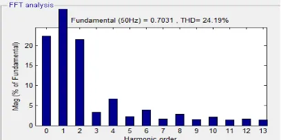
The Figure 10 shows the FFT analysis for source voltage for DVR with PI controller and the THD using that is 24.19%.
Fig.10: FFT analysis for Source voltage Using DVR with PI Controller
Figure 11 shows the FFT analysis for Load voltage for DVR with PI controller and the THD using that is 3.49%.
Fig.12: FFT analysis Injected Voltage Using DVR with PI Controller
Figure 13 shows the FFT analysis for source voltage for DVR with Fuzzy controller and the THD using that is 2.43%.
Fig.13: FFT analysis source voltage Using DVR with FL Controller
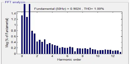
Figure 14 shows the FFT analysis for Load voltage for DVR with Fuzzy controller and the THD using that is 1.00%.
Fig.14: FFT analysis load voltage Using DVR with FL Controller
Figure 15 shows the FFT analysis for Injected voltage for DVR with Fuzzy controller and the THD using that is 2.55%.
Fig.15: FFT analysis Injected Voltage Using DVR with FL Controller
Table.2: FFT analysis Comparison of PI and FL Controller for DVR
S.NO FFT Analysis
THD % With PI Controller
THD % With FL Controller
1 Source voltage 24.19 2.43 2 Load Voltage 3.49 1.0 3 Injected Voltage 69.21 2.55
V.CONCLUSION
For both PI and FL controller, the simulation result shows that the DVR compensates the sag quickly (70μs) and provides excellent voltage regulation. DVR handles all types, balanced and unbalanced fault without any difficulties and injects the appropriate voltage component to correct any fault situation occurred in the supply voltage to keep the load voltage balanced and constant at the nominal value. The simulation based FFT results are shows, the fuzzy logic controller gave a better performance than the PI controller in improving the load voltage to normal conditions.
REFERENCES
[1] R. H. Salimin, M. S. A. Rahim. “Simulation analysis of DVR Performance for Volatge Sag Mitigation” The 5th International Power
Engineering and Optimization Conference. June 2011.
[2] Omar, R. Rahim, N.A. “New Control Technique Applied in Dynamic Voltage Restorer for Voltage Sag Mitigation” Industrial Electronics and
Applications, 2009. ICIEA 2009.
[3] Benachaiba, C. Ferdi, B. “Voltage Quality Improvement Using DVR”, Electrical Power Quality and Utilization, Journal Vol. XIV, No. 1,
2008.
[4] Wahab, S.W. Yusof, A.M. “Voltage Sag Mitigation Using Dynamic Voltage Restorer (DVR) System, ELEKTRIKA, 8(2), 2006, 32-37.
[5] IEEE Standard Board (1995), “IEEE Std. 1159-1995”, IEEE Recommended Practice for Monitoring Electric Power Quality”. IEEE Inc. New
York.
[6] Kim H. “Minimal Energy Control for a Dynamic Voltage Restorer”, In proceedings of the Power Conversion Conference, Osaka, Japan,
2002,pp. 428-433.
[7] V.K. Ramachandaramurthy, A. Arulampalam, C.Fitzer, C.Zhan, M. Barnes and N. Jenkins“Supervisory control of dynamic voltage restorers
“IEE Proc.-Gener. Transm. Distrib. Vol. 151, No. 4, pp. 509-516, July 2004.
[8] P. Boonchiam and N. Mithulananthan, “Understanding of Dynamic Voltage Restorers through MATLAB Simulation,” Thammasat Int. J. Sc.
Tech., Vol. 11, No. 3, July-Sept 2006.
[9] Nemati, M. Yousefian, H. A. Afshari, R. “Recognize The Role of A DVR in Power Systems” International Journal of Recent Trends in
Engineering, Vol 2, No. 7, November 2009.
[10] Mattavelli, P. Rossetto, L. Spiazzi, G. Tenti, P. “General- Purpose Fuzzy Controller for DC-DC Converter” IEEE Transactions on Power