GENERAL DESCRIPTION
The UNIVAC 1107
Contents
1. UNIVAC 1107 THIN-FILM MEMORY COMPUTER... ... 1
UNIVAC 1107 Features ... " ... , .. " .. .. . ... 1
Typical Applications. . . 2
Modularity.. . . 2
Peripheral Equipment ... 2
Operations in Brief ... '" ., ... '" .. . ... . 2
2. CENTRAL COMPUTER - STORAGE. . . 5
Control Memory... 5
Core Memory ... 5
Storage Allocation ... . . . 5
3. CENTRAL COMPUTER-CONTROL ... ... 7
Control-Memory Registers ... _ . . . 7
Indexing Unit... ... .... ... ... ... 9
I nterru pts . . . 9
Error Detection ... 9
Instruction Format ... 10
Repeated Sequences ... 14
Supervisory Consoie . . . .. 14
Initial Loading ... 15
4. CENTRAL COMPUTER - ARITHMETIC. . . .. 17
Partial Transfers ... 17
Arith metic Registers. . . .. 17
Double Precision Arithmetic ... 18
s. CENTRAL COMPUTER-INPUT-OUTPUT ... ... 19
General Characteristics ... 19
Functional Operation .. , ... " ... 19
6. PERIPHERAL EQUiPMENT ... 23
Magnetic-Drum Subsystem ... 25
Magnetic-Tape Subsystem ... 26
High-Speed Printer Subsystem ... 27
Punched-Card Subsystem ... 28
Paper-Tape Subsystem ... 28
Mass-Storage File Subsystem ... " ... 29
7. SYSTEMS PROGRAMMING ... , ... 30
8. INSTRUCTION REPERTOIRE ... 32
9. APPLICATION NOTES ... 37
Equipment Configuration ... 37
Utilization of Peripheral Equipment ... 37
1. UNIVAC 1107 Thin-Film
Memory Computer
The UNIVAC@ 1107 Thin-Film Memory
Computer represents the most significant departure from conventional data-process-ing systems since the introduction of solid-state circuitry. For the first time, a thin-film memory device is used in a commercially available computing system.
The many controls which must be exercised for high efficiency input-output, concurrent computation, and internal transfers are amalgamated in the heart of the computer. The busy computer crossroads, technically designated as registers, have been placed in the logic of this machine so that peri-pheral equipment can run at full speed with -little interference to running programs.
This ultra high-speed heart of the computer
has been made possible by another UNIVAC
first - Thin-Film Memory. UNIVAC Thin-Film Memory is made by deposition of mag-netic alloys under high vacuum in layers so thin that magnetization can b'e switched by rotation within time intervals of several
nanoseconds. Remington Rand UNIVAC'S
new technological breakthrough provides
multiple accumulators, ~ultiple index
reg-isters, and multiple input-output control registers. These multiple registers permit "housekeeping" steps to proceed in parallel 'with the main program and offer the advan-tages of multi-address logic where such logic is most efficient (for example, Search instructions) .
Basically, the 1!NIVAC 1107 is an advanced
solid-state data-processing system designed and developed to provide reliable solutions
to complex problems. This computer system is well suited to off-line, on-line, and real-time problems in commercial, scientific, and military applications. A highly versatile input-output section and a large internal memory, backed by a powerful instruction
repertoire, provide the UNIVAC 1107 with
unequalled data-processing capabilities.
UNIVAC 1107 FEATURES
Included among the many features of the
UNIVAC 1107 Data-Processing System are:
!!!! A thin-film control memory-the most advanced storage device on the market today - used for arithmetic and index registers, for input-output access control, for other special controls, and for auxiliary storage.
• 300-nanosecond (0.3-microsecond) access time for thin-film memory, with a complete cycle time of 600 nanoseconds.
• A ferrite-core memory for instructions and oper-ands, available in capacities of 16,384 words in one bank; or of 16,384, 32,768, 49,152 or 65,536 words in two separately accessed banks_
• 2-microsecond effective cycle time for core stor-age (overlapping of two banks).
• 36-bit words in both thin-film and core memories. • An instruction word format that provides for
in-dexing, automatic index-register incrementation, partial word transfers, and indirect addressing, along with a current operand reference and speci-fication of an arithmetic register.
• An extremely powerful instruction repertoire, in-cluding fixed and floating-point, integer, and frac-tional arithmetic.
• Automatic programming: ALGOL and COBOL com-piling programs and a FORTRAN translating pro-gram.
• An Executive Routine, capable of integrat.ing rou-tines for multiple programs.
• Compatibility with existing UNIVAC systems is maintained through Uniservo IIA, gO-column and SO-column punched-card, and paper-tape peri-pheral units. Versatile off-line communication with peripheral units can be accomplished by including a UNIVAC Solid-State or UNIVAC STEP system as a satellite computer.
TYPICAL APPLICATIONS
In line with UNIVAC's leadership in de-veloping and manufacturing computing systems of advanced logical design, the UNIVAC 1107 offers the most advanced data-processing capability now available. This general-purpose system can efficiently and economically handle a wide range of tech-nical applications, such as:
• Tactical data systems
• Command and control systems
• Digital communication and switching systems • Data reduction and analysis
• Logistics
• Scientific computation • Traffic control • Reservation systems • Computational analysis
• Inventory and scheduling systems • Intelligence systems
• Systems simulation
• Missile and satellite dynamics • Process control
MODULARITY
Because the storage capacity and the num-ber of input-output channels activated are optional, the user can select a UNIVAC 1107
System that will meet his immediate
proc-essing and cost requirements. The system selected can then be expanded at a rate con-sistent with the quantity and complexity of applications.
Compatibility with a wide range of com-mercial, scientific, and military peripheral equipment-of be>th advanced and standard design - complements the basic building-block characteristic. Consequently, the UNIVAC 1107 System can be varied on the basis of size, components, or applications.
In any particular application a configura-tion can be chosen that will provide a well-balanced system with unprecedented growth potential.
Along with modular construction, the UNIVAC 1107's unique input-output section - designed to be adaptable to new peri-pheral equipment - assures the user of a data-processing system that will keep pace with the computer industry far into the foreseeable future. This section can connect the Central Computer with many different types of peripheral units, including other Central Computers.
PERIPHERAL EQUIPMENT
The list of peripheral equipment compati-ble with the UNIVAC 1107 Thin-Film Mem-ory Computer includes:
Standard Peripheral Equipment: Magnetic Drums
Magnetic-Tape Units Punched-Card Units High-Speed Printers Paper-Tape Subsystems Supervisory Console Auxiliaries Special Peripheral Equipment:
Analog-to-Digital and Digital-to-Analog Converters Electronic Printers
Displays, Plotters, and Keysets Multiplex and Switching Units Special Real-Time On-Line Systems Mass-Storage Units
Other Off-Line Systems Other Computers
OPERATIONS IN BRIEF
Memory
Regardless of the core-memory capacity selected by a user (capacities range from
16;384 to 65;536 words); every UNIVAC
1107 System employs a separate thin-film control memory. This memory, which is the latest development in storage techniques, consists of an array of thin magnetic films. The time required to obtain information from the UNIVAC 1107's thin-film memory is only 300 nanoseconds (0.3 microsecond). Very high operating speeds can be achieved because the thin-film control memory al-lows parallelism and sophisticated logic.
Each instruction does more work.
In addition to providing auxiliary storage locations, the control memory furnishes:
15 Index Registers 16 Arithmetic Registers* 36 Special Control Registers
Instructions
The instruction repertoire encompasses both fixed and floating-point arithmetic. Fixed-point instructions, in turn, provide for integer and fractional arithmetic.
Pro-* Four arithmetic-register addresses overlap index-reg-ister locations.
vision has also been made for partial word transfers, partial compares, repeated search operations, and masking. Special add and subtract instructions nerform nar-allel addition or subtraction of two or three fields within a single data word. To provide fast programming of double-precision arithmetic, special features have been in-corporated in the arithmetic section.
Input-Output Channels
The UNIVAC 1107's input-output channels have been paired to meet the requirement that standard peripheral equipment accom-modate bidirectional data transfers. Up to 16 input channels and 16 output channels can be used for direct communication be-tween peripheral equipment and internal memory.
Program Interrupt
r: - - -
-
-
-
-
-
- -
-
-
-
-
-
-
-
-
-
- - l
I
~--I
I
I
MEMORYI
I
1- - - -
---1
,~~~~~~--~--~~--~--~
I
I
I
I
I
I
I
I
I
1
- - - -...
MAIN CONTROL
L _____ _
--!--
I
I
I
I
L ____ _
ARITHMETIC
I
I
---l
INPUT ·OUTPUT
CONTROL
I
---~
PERIPHERAL
• • • EQUIPMENT
I
2.
Central Computer-Storage
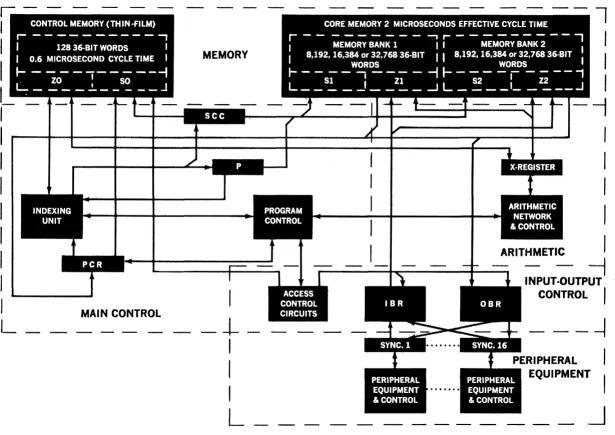
The Central Computer in the UNIVAC 1107
System comprises four major sections: storage, control, arithmetic, and input-out-put. A block diagram of the Central Com-puter is presented in Figure 2-1.
The storage section consists of control memory and core memory, along with their associated address, transfer, and control circuits. Memory is addressed via storage
class control (See) from the indexing unit,
program control register (peR), and
con-trol registers located in the concon-trol memory.
Each address is decoded by see to
deter-mine whether reference is to be TIlade to control memory or to core memory bank one or two. The address is then transmitted to the appropriate storage address register
(SO, Sl, or S2), and the corresponding memory reference is initiated.
CONTROL MEMORY
The 128-word control memory consists of deposited magnetic films. The film array has word selection and operates in the par-allel mode. Read access for any address is 300 nanoseconds; complete cycle time is 600 nanoseconds.
CORE MEMORY
Core memory consists of modular arrays of ferrite cores with coincident current selec-tion. Capacity options are 16,384 words in one bank, or 16,384,32,768,49,152 or 65,536 words in two banks. Read access time for
any address is 1.8 microseconds; complete cycle time is 4.0 microseconds. The two banks function as separate units which are overlapped to provide an effective cycle time of 2 microseconds.
\Vriting into specified regions of core mem-ory may be suppressed by a special memmem-ory write lockout instruction (Function Code 72-11). This core-memory lockout can pro-tect any 8 memory regions (which could include the entire core memory) from undesired writing operations. The single address 201 (311 octal) containing the external status word cannot be locked out, since it must always be available for the external interrupts.
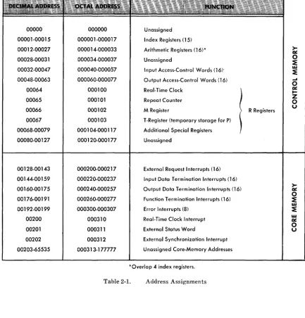
STORAGE ALLOCATION
The first 202 of the 65,536 addresses are used as shown in Table 2-1. Core memory addresses have the lower range in bank one and the higher range in bank two.
00000 00001-00015 00012-00027 00028-00031 00032-00047 00048-00063 00064 00065 00066 00067 00068-00079 00080-00127 00128-00143 00144-00159 00160-00175 00176-00191 00192-00199 00200 00201 00202 00203-65535 NAME FUNCTION BITS 000000 000001-000017 000014-000033 000034-000037 000040-000057 000060-000077 000100 000101 000102 000103 0001 04-000117 000120-000177 000200-000217 000220-000237 000240-000257 000260-000277 000300-000307 000310 000311 000312 00031 3·177777 Unassigned Index Registers (15) Arithmetic Registers (16)* Unassigned
Input Access-Control Words (16)' Output Access-Control Words (16) Real-Time Clock
Repeat Counter M Register
T-Register (temporary storage for P) Additional Special Registers Unassigned
External Request Interrupts (16) Input Data Termination Interrupts (16) Output Data Termination Interrupts (16) Function Termination Interrupts (16) Error Interrupts (8)
Real-Time Clock Interrupt External Status Word
External Synchronization Interrupt Unassigned Core-Memory Addresses
*Overlap 4 index registers.
Table 2-1. Address Assignments
G ( 2 bits) DO-Increment V Ol-Inhibit Increment V IO-Decrement V ll-Inhibit Decrement V
R Registers
W (16 bits) -Number of words remaining to be transferred V (18 bits) -Address of current data transfer
Figure 2-2. Format of the Input-Output Access Control Word
3. Central Computer-Control
The control memory provides special stor-age assignments for index registers, arith-metic registers, input-output access control, a mask register, the real-time clock, a re-peat count, temporary program address storage, and auxiliary storage.
CONTROL=MEMORY REGISTERS
The B-registers, the A-registers, and the R-registers have what is termed "two-address accessibility." That is, they may be referenced directly either by the operand-address portion of an instruction or by a special designator contained in certain instructions. This feature is further ex-plained in the description of the instruction word format.
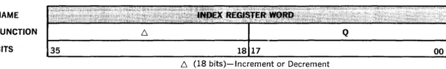
Index Registers
Fifteen index registers (or B-registers) are used for operand address modification, index counts, and modifier incrementation. The right half of the index word contains the I8-bit address modifier. The left half of the index word contains the I8-bit incre-ment (decreincre-ment). The modifier is added to the base execution address of the instruc-tion to obtain the effective address. A con-trol bit in each instruction then specifies whether the increment is to be added to the modifier. Special index register
instruc-NAME
FUNCTION
BITS
tlOns test the modifier. The indexing unit is an I8-bit arithmetic unit which can per-form addition and subtraction in one's complement arithmetic. This unit handles both address modification and incrementa-tion (decrementing) of the modifier in par-allel with the main arithmetic sequence. The index vlOrd format is sho\vn in Figure 3-1.
Arithmetic Registers
Sixteen arithmetic registers in the control
memory provide interim high-speed stor~
age for arithmetic operations. From a pro-gramming viewpoint, these arithmetic registers (A-registers) function as 16 ac-cumulators. The actual accumulation is performed in the arithmetic section with the result stored in the A-register (s) speci-fied by the instruction. Because of the
over-lap of addresses (Table 2-1), four
A-registers can be directly designated as index registers.
• With four arithmetic registers capable of function-ing as index registers, the UNIVAC 1107 System can perform highly sophisticated address modi-fication.
Input-Output Access Control Registers
Thirty-two control-memory addresses are used for storing input and output access
Q
001
!::, (18 bits)-Increment or Decrement
Q (18 bits)-Modifier
control words. The function of these words will be discussed in the input-output section.
R-Registers
Sixteen control-memory addresses are des-ignated as "R-registers." Four of the 16 R-registers are assigned specific functions as explained below; the remaining 12 may be used in any way the programmer desires
(except for instruction storage).
Of the four specially assigned R-registers, one is used for the real-time clock. The 36-bit number contained in this register is decremented by one every millisecond (the
exact granularity being 2-10 seconds). When
the count is reduced to zero, an internal interrupt occurs which causes the program to jump to address 200 (octal 310). The direct two-address accessibility of the clock simplifies presetting the count, reset-ting it during operation, and subsequently reading it out.
NAME
FUNCTION
BITS
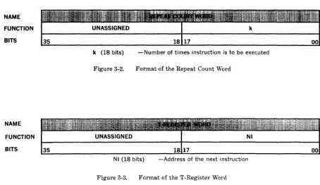
The second of the four assigned R-registers is used for the repeat count, containing the number of times a repeated instruction is
to be executed (k). The format of the repeat
count word is shown in Figure 3-2. Each time a repeated instruction is executed the
k is reduced by one. The repeat function
terminates when k is reduced to zero. The
unassigned left half of the repeat count
word may be used to "park" the total
num-ber of times an instruction is to be repeated.
The third assigned R-register is the M- or
masking register. The M-register contains the mask used in certain logical and test instructions (Function Codes 43 and 71).
The fourth assigned R-register is the T-reg-ister. This register is used as a temporary par king register to hold the address of the next instruction, NI, during the execution of a repeated instruction. During the execu-tion of nonrepeated instrucexecu-tions, this ad-dress is not referenced by main control. The format of the T-register word is shown in Figure 3-3.
k (18 bits) - Number of times instruction is to be executed
NAME
FUNCTION
BITS
Figure 3-2. Format of the Repeat Count Word
Nt (18 bits) -Address of the next instruction
Control Circuits
The main control and timing circuits supply control signals which synchronize the exe-cution of the instructions. The particular instruction to be executed is determined by the contents of the program-control regis-ter.
INDEXING UNIT
The indexing unit, containing an adder and
sen~ing circuits, is shared by program con-trol and input-output concon-trol. Program control uses the indexing unit to advance the P-register, to "count down" k in the repeat count register, to control repeated sequences, and to perform the indexing op-erations. The indexing operations include the addition of the modifier to the base address to obtain the effective execution address, the addition of the increment to the modifier, and various tests of the modi-fier. Input-output control uses the indexing unit to increment (decrement) the data-transfer address and to decrement the word count.
INTERRUPTS
An interrupt is a special control signal which diverts the "attention" of the com-puter to "consider" an extraordinary event or set of circumstances; that is, it causes program control to be transferred to a spe-cial subroutine which corresponds to the "stimulus." Many levels of control can be exercised by the numerous forms of inter-rupts provided. The interinter-rupts from external sources serve primarily to syn-chronize the computer program with the readiness of peripheral devices, including other computers, to transmit or receive data. Internal interrupts serve primarily to synchronize the computer program with the termination of input-output transfers and to signal the occurrence of an error.
An interrupt causes the next instruction to be procured from a fixed address corre-sponding to the interrupt source. This fixed address serves as a subroutine entrance by
containing a 1'eturn jump instruction. The
return jump instruction transfers the
con-tents of P, which is the address of the
instruction which otherwise would have been executed, to the first address of the subroutine, thereby providing the subrou-tine exit. Program control is then trans-ferred to the second address of the subroutine.
Several classes of interrupts are provided. An external-request interrupt with a fixed address for subroutine entrance corre-sponds to each of the 16 input channels. The 16 external-request interrupts enable external devices connected to the input channels to demand the attention of the computer as required. An internal inter-rupt with a fixed address for subroutine entrance corresponds to each of the 16 in-put access control words, 16 outin-put access control ·words, and 16 external function words. An internal interrupt with a fixed address for subroutine entrance is provided for the real-time clock.
An additional external interrupt with a fixed address for subroutine entrance is provided for real-time system
synchroni-zation. This interrupt is independent of the input-output channels. The synchronization interrupt accepts signals from an external generator of any desired frequency. The external generator may be a supplementary real-time clock for the computer or the mas-ter clock of a multi-compumas-ter complex. The fixed address assignments for the various classes of interrupts are shown in Table 2-1.
The occurrence of an interrupt causes a lockout to prohibit the occurrence of fur-ther external interrupts until the
instruc-tion, enable all external interrupts, is
executed. The 16 external input interrupts may also be disabled under program control
(Function Code 75).
ERROR DETECTION
ad-dress is provided for each of eight types of internally detected errors. These inter-rupts cannot be disabled or locked out. Upon detection of an error, control is trans-ferred to an appropriate error address
(subroutine entrance) in a manner similar to the other interrupts. Action is taken by the subroutine and control is then returned to the main program.
The error detection includes illegal function code and attempted write into a locked-out area of memory; these are indicated to the computer operator as program faults. De-tection of arithmetic errors includes float-ing-point characteristic overflow and underflow and stated-point-divide overflow. Parity checks are also made on peripheral equipment.
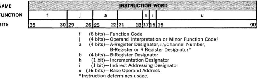
INSTRUCTION FORMAT
The operation of the computer is controlled by a program of instructions stored in memory. Each instruction is read from memory, normally from sequential ad-dresses, and then is transmitted to the program control register for interpreta-tion. Each instruction consists of several parts called designators. These are identi-fied by letters and are listed below as they appear from left to right in the instruction word. (See Figure 3-4.)
The execution of an arithmetic instruction
includes the following step~ :
1. Read out (Bh ) from film memory
speci-fied by the b designator of the current
instruction.
2. Store the result of the previous instruc-tion at Aa of thin-film memory specified
by a of the previous instruction.
3. Add (B) () to u where b =1= 0 for current instruction.
4. Store the second part of the result of the previous instruction at Aa
+
1 "in film memory at the address one higher than that used in Step 2, if applicable.5. Initiate access to the operand with the
effective address obtained from Step 3. The storage reference may be made to film memory or core memory.
6. Initiate access to NI. This storage ref-erence is made to core memory.
7. Read out (Aa) from film memory
speci-fied by a of the current instruction.
8. Add (B),6 to (B) () if specified by h of the current instruction.
9. Store index register word at the film memory address used in Step 1.
10. Initiate arithmetic operation.
11. Initiate input-output word transfers if requested and then proceed to Step 1.
The above steps take 4.0 microseconds for most instructions when the operand refer-ences are made either to film memory or to the alternate core memory bank. Instruc-tion execuInstruc-tion time is extended by 4.0 microseconds when the operand reference is made to the same bank as the instruction reference. Most arithmetic operations are performed in less than two microseconds. Certain arithnletic operations require more than two microseconds and thereby extend the instruction times beyond 4.0 micro-seconds. Each input-output word transfer increases the instruction time by 4.0 micro-seconds, with the exception of extended arithmetic instructions, where
input-out-put word transfers can occur simultane-ously with the arithmetic sequences. For example, two input-output word transfers
and the Floating Multiply instruction take
12.7 microseconds total. Three input-output word transfers with this instruction take 16.0 microseconds total.
When the A-register used in Step 2 above is the sixteenth A-register, the second part of the result is stored at the next address 00028 (00034 octal) in Step 4.
NAME
FUNCTION
BITS
(6 bits)-Function Code
(4 bits)-Operand Interpretation or Minor Function Code* a (4 bits)-A-Register Designator,l/oChannel Number,
B-Register or R Register Designator';' b (4 bits)-B-Register Designator
h (1 bit)-I ncrementation Designator (1 bit)-Indirect Addressing Des"ignator u (16 bits)-Base Operand Address ';'Instruction determines usage.
Figure 3-4. Format of the Instruction Word
The program control overlaps as much of the instruction sequencing as practical. For example, in an arithmetic instruction which augments an A-register, the initial content of the specified A-register is transferred to the arithmetic unit concurrently with an operand reference to core memory. Simi-larly, the steps for procurement of the next instruction are undertaken before the sequencing of the current instruction is completed.
Function Code, , (6 Bits)
The left-hand 6 bits of the instruction word designate the function to be performed by that instruction. In some instructions,
where the normal meaning of j is not
ap-plicable, j is combined with
f
as a 10-bitfunction code. Values of
f
(orf
and j)which are not meaningful are fault condi-tions which cause an error interrupt, and the program will jump to a fixed memory address which is the entrance to an error routine.
Operand Interpretation, ; (4 Bits)
The j designator normally defines that part
of the operand that is to be transferred to and from the arithmetic unit. These values
of j are given in Figures 3-5 and 3-6 .
A-Register Designator, a (4 Bits)
During arithmetic instructions, this desig-nator specifies anyone of the 16 A-regis-ters. These fast registers are also directly
addressable by the operand address. In some instructions such as block transfer,
load Ba , and test modifier, the a-designator
specifies the index registers (using the
no-tation Ba). For these instructions a specifies
one of 16 index registers (for example, a
=
o
specifies address 00000). Theinput-out-put control instructions use a to specify the
channel to be used. In other instructions,
a designates an R-register. In one
instruc-tion, index jump, a and j taken together
designate anyone of the 128 words of con-trol memory.
B-Register Designator, b (4 Bits)
The b-designator of the instruction speci-fies which of the 15 index registers, if any, is to take part in the modification of the
operand address designator, u. No address
modification occurs for b
=
O.Incrementation Designator, h (1 Bit)
This designator specifies incrementation of the modifier of the index register desig-nated by b as follows:
h = 0, No incrementation
h = 1, (B) Q
+
(B) 6 ~ (B)QIndirect Addressing Designator, ; (1 Bit)
This designator specifies either normal or indirect addressing of the operand. Indirect addressing denotes that the effective
ad-dress of the operand is contained in the
"
J •
I
•
u
I
..
I
"
00
1.
II 00 .I
1
35 30
1
•
•
$
.
II
1.;"\..
--
l
os
DOll(I.
1
•
II
J.
I
,
.
..
<
<- ,
"
~I'
1.1
J!I!
'
~
I'
..
l~
"
,.
.
•••
II
•
. . 17oolX
•
II~OOZ
"P
•
11 IIOOlx
"
,
•
IS•
U 11 0011.J'
I
,
."; =
I
0500
r
,.
that is, U is the address of an address. If the indirect address indicator thus obtained
from the right 22 bits of the word at the U
address indicates indirect addressing is to be used, the process is repeated; that is, the indirect addressing is cascaded. The speci-fication of indirect addressing is as follows:
i = 0, Direct addressing applies. The
ef-fective address is U
=
u+
(B) Q.i = 1, Indirect addressing applies. The
effective address is provided by the right 22 bits of the memory location given by U
=
u+
(B) Q. Since the b,h, i, and u portions of the program
control register are replaced, the in-dexing, incrementing, and indirect addressing can be cascaded.
Base Operand Address, u (16 Bits)
The operand address, made up of the base address plus any specified modification, des-ignates which of the possible 65,536 storage locations will be referred to in the execu-tion of the instrucexecu-tion. Most instrucexecu-tions refer to a storage location once during the
execution of an instruction. When j equals
16 or 17 (octal), the effective operand is taken directly from the instruction word. The instruction does not reference the ad-dress of an operand but instead contains
the operand within itself. U also provides a
shift count.
REPEATED SEQUENCES
Thirteen instructions operate in a repeated
sequence mode: block transfer and repeated
search. The number of times the function
is to be executed is specified by k, which is
retained in the repeat count register.
As part of the preparation for the execu-tion of a repeated sequence, the repeat
count register is loaded with the load Ra
instruction. During the repeated sequence
mode, the instruction is retained in peR
and P is not consulted for the next
instruc-tion. Each time the function is executed, k
is counted down by one and tested for zero.
If k does not equal zero, the function is
repeated. When k equals 0, the normal
se-quence of procuring the next instruction
from P is resumed.
An interrupt which occurs during a re-peated sequence temporarily halts the repeated sequence mode and causes a jump to the fixed address corresponding to the interrupt. This termination is performed in a manner that allows the return from the interrupt subroutine to reinitiate the re-peated sequence from the point of inter-ruption. When an interrupt temporarily
halts a repeated sequence, P is set back to
the address of the instruction which set up the repeated sequence mode.
In the termination of a search instruction
by a jump or skip condition, P is treated in
the normal manner.
The contents of the applicable control reg-isters prior, during, and subsequent to execution of a repeated instruction are sum-marized as follows:
Prior to repeated sequence
P-register: P.
Repeat count register: k, number of
times instruction is to be executed.
T -register: Not applicable.
During repeated sequence
P-register: k, number of times
instruc-tion is to be executed.
Repeat count register: k
=
initial k.T -register: Temporary storage of P.
After repeat termination
P-register: P.
Repeat count register: k = number of
times remaining in sequence (for
nor-mal termination, k = 0; for jump or
interrupt termination, k ~ 0).*
T-register: Not applicable.
SUPERVISORY CONSOLE
The Supervisory Console includes the op-erator's control panel, a keyboard and type-printer, and a control unit for the keyboard and type-printer. Optionally, a Paper-Tape
Reader and Punch may be connected to the computer through the same control unit. Information transfer between the com-puter and any single device is perforriled on a character basis over the input channel and output channel assigned to the console auxiliaries. Two switches mounted on the control unit permit selection of the Paper-Tape Reader or the keyboard and the Paper-Tape Punch or the type-printer.
Operator's Control Panel
This panel provides direct operator com-munication with the computer. The manual controls and indicators provided allow the operator to:
1. Stop computer program execution but
allow the input-output section to con-tinue operation.
2. Clear all computer registers except those in the input-output section.
3. Master clear all computer registers in-cluding those in the input-output sec-tion.
4. Start computer program execution. The program will start with the instruction located at the address indicated by the six octal digit indicators of the P-reg-ister.
5. Set the desired address into the P-reg-ister for starting program execution.
6. Set any of the fifteen (15) selective
jump switches. An indicator is lit when the corresponding jump is selected. These jumps can be selected while the computer is running.
7. Set any of the four (4) selective stop
switches. vVhen the selection is made, the upper half of the corresponding selection indicator is lit, and when the stop is made the corresponding stop indicator is lit. These stops can be selected while the computer is running.
8. Read in an initial loading (bootstrap) program from input channels.
9. Select one of the sixteen (16) channels
for the initial load of the bootstrap pro-gram.
In addition to the above manual controls and indicators, four (4) fault or status in-dicators are provided. These are:
1. Computer Status-for example, excessive temperature, poor voltage regulation.
2. Program Faults-for example, illegal op-eration code, illegal memory access
(memory lockout) .
3. Peripheral Equipment Fault-for exam-ple, loss of power in a channel synchro-nizer or control unit, disconnected cable.
4. Initial Loading (bootstrap) Fault-error
occurring during the loading of the Boot-strap program.
Keyboard
The keyboard is an assembly consisting of a standard four-bank typewriter keyboard. The keyboard can generate 64 basic char-acters, among which are the 51 charac.ters of COBOL (COmmon Business Oriented Language).
Type-Printer
The type-printer is a
10-character-per-sec-ond printer. It is capable of printing the 26
alphabetic characters, 10 numeric charac-ters, and 19 special printable characters of the basic 64-character code. It will also respond to 9 control codes (space, carriage return, and so forth). All 51 of the COBOL Characters are printed.
INITIAL LOADING
transfer is established with a monitor for 160 words. The peripheral equipment ter-minates any current operation and starts transmitting data from address zero, if a drum; or block zero, if magnetic tape; from the first available punched card; or from the first frame, if paper tape.
When all 160 words have been entered into the computer, the main program is trans-ferred to the program contained within
these 160 words via the input-data-termin-ation interrupt.
4. Central Computer-Arithmetic
The arithmetic section includes an adder, temporary storage registers, a sequence counter, shift matrix, threshold-sensing circuits, and arithmetic-sequence control circuits. The adder is a 36-bit one's
comple-ment subtractive adder (mod 236-1). The
counter is employed during multiply and divide operations. The threshold-sensing circuits determine equality and relative magnitude of the contents of registers specified by the instructions. The arith-metic-sequence control circuits govern the execution of the algorithms for addition, subtraction, multiplication, division, shift-ing, and testing relative magnitudes.
As may be seen from the instruction reper-toire, a complete range of fixed- and float-ing-point arithmetic operations is provided. Addition and subtraction of two or three fields (vector components) within the data word can be performed in the same time as an ordinary add instruction.
Three very important features make the arithmetic section unique.
1. Word transmissions between the arithmetic sec-tion and core memory can be directly segmented into halves, thirds, and sixths.
2. Operands and results are retained in 16 directly addressable arithmetic registers (A-registers) in the thin-film control memory.
3. Results of arithmetic operations are retained in thin-film memory in double-precision form. This feature, through the use of thin-film accumula-tors, facilitates programming double-precision arithmetic operations.
PARTIAL TRANSFERS
A four-bit portion of the instruction
desig-nated j, specifies the mode of transmission
to or from the arithmetic section. Figure
3-5 shows the data paths
to
the arithmeticsection from the storage transfer register
(Z) of core memory. When j is 16 or 17
(octal), the effective operand is taken di-rectly from the instruction word. (That is, the instruction does not reference the ad-dress of an operand but instead contains the operand within itself.) All partial words enter the lower-order positions of the
X-register and, with the exception of j
=
1,2, or 10-16 (octal), the sign is extended to the higher-order positions.
• The automatic shifting of partial words to lower-order positions in the X-registei' is extremely valuable both in terms of programming and proc-essing. With this feature, computation can fre-quently be performed immediately after the partial words have been transferred, without first calling for "housekeeping," such as shift instructions.
Figure 3-6 shows the data paths for data
transfers from the arithmetic section to
core memory as specified by j. In this case
the rest of the core word is not changed.
In instructions where the partial word
des-ignation has no significance (f = 70,71, 72,
73, 74,75,76, octal), the j code is treated as
part of the regular function code to specify various instructions.
ARITHMETIC REGISTERS
A four-bit portion of the instruction,
A-registers in control memory. Specifica-tion of an A-register as well as a regular execution address provides much of the flexibility of mUltiple address instructions.
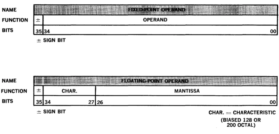
Arithmetic operations are performed in the arithmetic unit utilizing temporary storage registers. These registers retain no initial or final results from one instruction to an-other. All such results are retained in the A-registers specified by the instructions. The A-registers function as 16 accumula-tors from the programming point of view. The fixed- and floating-point word formats are shown in Figure 4-1.
DOUBLE PRECISION ARITHMETIC
Most arithmetic instructions preserve two word intermediate results. In the case of stated-point multiplication, a double-length product is stored in the A-registers of con-trol memory for integer and fractional operations. Integer and fractional division are performed upon a double-length divi-dend with the remainder preserved for use as the dividend in the next instruction if desired. An overflow indication from addi-tions is retained for programmed tests as desired.
NAME
FUNCTION
BITS
NAME
FUNCTION
BITS
± SIGN BIT
± SIGN BIT
The floating-point instructions for addi-tion, subtracaddi-tion, and multiplication always store a two-word result. Data words need not be normalized. Floating-point division requires that the divisor have at least as many significant bits as the dividend. Float-ing-point addition provides the most sig-nificant word normalized and stored in an A-register and the least significant word without normalization stored at the next higher addressed A-register. Both results contain their appropriate characteristics. A full double-precision addition can be ob-tained from four single-precision additions.
The floating-point product of two normal-ized numbers produces either 53 or 54 bits
of product. Wherever 53 occurs a left shift
of one results. Therefore, the product of normalized values yields normalized results, while the product of unnormalized values yields un normalized results. In either case, the characteristics of the two word results always differ by 27. Three floating-point multiplications and additions will yield a double-precision result except for the ex-treme right portion in the register contain-ing the least significant half.
CHAR. = CHARACTERISTIC
(BIASED 128 OR 200 OCTAL)
5. Central Computer-Input-Output
GENERAL CHARACTERISTICS
The input-output section provides the data paths and control circuits necessary for di-rect communication between the core mem-ory banks and the peripheral equipment. A communication path between computer and peripheral unit is initially established by the main computer program. Thereafter, the individual transfers are governed by the input-output access-control circuits, which monitor the number of words to be transferred and specify the addresses in core memory to and from which the data are transmitted. As previously mentioned, the access-control circuits service the re-quests of each external unit until the speci-fied sequence of word transfers has been completed. Thus these circuits free the re-maining sections of the computer enabling them to continue with the execution of the main program.
Working in conjunction with the access control circuits, priority control circuits resolve situations where two or more
exter-nal equipments simultaneously attempt to
communicate with the computer. In each case, priority is given to the one with the lowest channel number.
Up to 16 output and 16 input channels can be in concurrent operation. However, the number that can be handled efficiently is a function of the data transfer rate of the peripheral equipment. (In general, faster transfer rates tend to reduce the number of channels that can be handled efficiently.) In most cases, both an input and an output channel are used with the same peripheral equipment to provide bidirectional data
transmission. The capability of the input-output section to provide separate and dis-tinct control over input-output channels accommodates specialized peripheral de-vices in real-time applications. Concurrent word transfers are multiplexed to pro-vide a maximum communication rate of 250,000 words per second (1,500,000 char-acters per second). Conventional off-line operations, such as card-to-tape conversion, can be performed as on-line operations with negligible interruption of other programs. In this type of operation, the information flows to and from an assigned memory area, serving as a transfer buffer,
FUNCTIONAL OPERATION
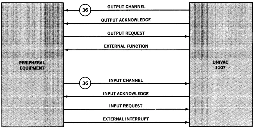
The computer establishes communication with the peripheral equipments by sending control codes (external function words) over the output data lines. Thes€ external function words are distinguished from data words because they are accompanied by a signal over the external function line, a special control cable between the computer and the peripheral equipment. Through the use of external function words, the com-puter, in normal operation under program control, can activate or deactivate peri-pheral units.
The normal control signals used to transfer wordR to and from the computer are shown in Table 5-1. The lineR linking the computer
to the peripheral equipment are illustrated in Figure 5-1.
Output Request
Output Acknowl-edge
Input Request
Input Acknowl-edge
Interrupt
External Function
Output Unit
Computer
Input Unit
Computer
Peripheral Unit
Computer
Output unit is ready to receive next output word.
Computer has transmitted next output word.
Input unit is ready to transmit next input word.
Computer has received last input word.
Peripheral unit requires output from (or input to) computer.
Word on data lines is an external function word.
Computer forms next output word and sends output acknowledge.
Initiates cycle whereby output unit accepts and processes output word.
Computer accepts input word and sends input
acknowledge.
Initiates cycle whereby input unit produces next input word.
Causes program to jump to interrupt subroutine for that channel.
Peripheral control unit decodes function word.
NOTE: The terms "output" and "input" are referenced with respect to the computer.
Table 5-1. Input-Output Control Signals
OUTPUT CHANNEL
OUTPUT ACKNOWLEDGE
OUTPUT
EXTERNAL FUNCTION
INPUT CHANNEL
IN
INPUT REQUEST
Information is transferred to or from the computer's core memory in blocks of data. A block of data is defined as a series of
addresses starting with a program-deter-mined first word and ending with a pro-gram-determined last word. Block length is limited only by the size of the memory and the addresses of the first and last words of the block.
As indicated in the repertoire of instruc-tions, a block transfer can be established in one of two ways: with a monitor or without a monitor. "With a monitor" means that an internal interrupt will be generated at the conclusion of the transfer; "without a monitor" means that this interrupt will be inhibited.
The word-by-word transfer of data to or from the computer is governed by an input-output "access-control word." One such word is assigned to each channel. Input and output access-control words have the same format. (See Figure 2-2.)
The output-access-control word serves two purposes: it controls the transfer of output data words, and it controls the transfer of the external function words previously mentioned. The input-access-control word governs only the transfer of input data words.
As shown in Figure 2-2, the access-control word consists of three parts: G is the "transfer mode designator," the use of
which is explained below; V is the starting
address of the data transfer; and, W is the
number of words to be transferred.
The computer program initiates an input-output transfer in the following manner:
1. The program compiles a list of external function words necessary to define the desired operation to the peripheral equipment. This list may be one or more words long.
2. An initiate monitored function mode instruction is executed, which begins the transmission of the list to the peripheral equipment. The rate at which the external function words are trans-mitted is governed by the output request signal rate of the peripheral equipment. A tape control unit, for example, may receive instructions to
initiate read, initiate write, search tape, or rewind the specified tape unit.
3. After the last external function word is
trans-mittpri ::In intprn::ll intprrllnt (rpC:llltina frnrn th~
- - - : _ . . . __ . . . _ . . . . __ . . -... \.· ... _ ... b .~ ... ~ ~rl_
monitor) occurs which notifies the program that data transmission may begin. Normally, the main program will then jump to a subroutine which initiates data transfer.
4. As part of the subroutine which initiates data transmission, there occurs an initiate output (or input) mode instruction which transmits an out-put (or inout-put) access control word to the location in control memory corresponding to the particular channel. The initiate output (or input) mode in-struction mayor may not specify a monitor. Once the instruction is given, data transfers occur at the natural rate of the peripheral equipment.
The first data transfer references address
V, as specified in the access-control word.
The second transfer references address
V (G = 01 or 11) , address V
+
1 (G = 00) ,or address V - I (G
=
10). Thus thecondi-tion of G determines whether the same ad-dress is referenced, or whether adad-dresses in ascending or descending order are refer-enced.
Referencing the same address for succes-sive data transfers is an unusual feature
which requires explanation. As~mme for
example that some input (or output) unit has a natural rate much slower than that of the computer. Successive input (or output) words may then easily be processed by the main program in real-time without using more than one address in core memory. (Such operation demands that the main program be synchronized in some manner with the natural rate of the peripheral equipment.) Or again assume that the same word is to be written repeatedly on a peri-pheral device; setting G equal to 11 or 01 will accomplish the function.
As the successive data transfers occur, W,
which specifies the number of words in-volved in the transfer,. is decremented.
When W reaches zero, the transfer is
ter-minated. If a monitor was established, an internal interrupt for that channel is gen-erated.
transmis-sions at the same time. Therefore, one unit of special peripheral equipment may use an input channel while a different unit uses the corresponding output channel for simplex operations .. Other special peripheral equip-ment, using both an input channel and the corresponding output channel, can be oper-ated with simultaneous input and output transfers in a full-duplex mode of commu-nication. The standard peripheral units dis-cussed below use an input channel and the corresponding output channel for bidirec-tional communication, but not at the same time, in a half-duplex mode of communica-tion. Different priority for input and
out-put communication with a peripheral sub-system can be achieved with the use of input and output channels of different number.
&.
Peripheral Equipment
The input-output section of the UNIVAC
1107 is capable of utilizing a large variety of peripheral equipment. Some units of pe-ripheral equipment may be used to provide a hierarchy of auxiliary storage; for exam-ple, drums, mass storage, and tapes. Other units may serve as input or output (origin or destination) equipment; for example, card units, printers, and paper-tape sub-system. Other units may serve as informa-tion links to other systems. With the adap-table input-output section, the computer can communicate with many real-time de-vices, such as analog-to-digital and digital-to-analog converters, keysets, printing telegraph equipment, digital communica-tion terminals, digitized radar and tracking systems, display systems, other sensing and instrumentation systems, and other infor-mation-processing systems.
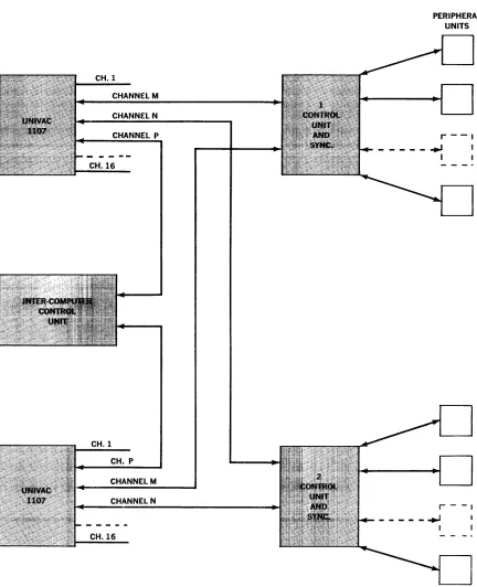
The standard peripheral equipment units use an output channel and the correspond-ing input channel to effect bidirectional communication. The typical interconnec-tion of standard peripheral equipment to the UNIVAC 1107 is shown in Figure 5-1. The output channel (36 lines) provides function words and data words to the peri-pheral equipment. The input channel (36 lines) provides data words and status, in-cluding error conditions, to the computer from the peripheral equipment. The Higb-Speed Printer uses an input channel to re-port status information to the computer and uses an output channel to receive data and external functions.
Each subsystem of peripheral equipment consists of one or more peripheral devices of the same type, a peripheral control unit
for the particular type of device, and a channel synchronizer. The channel syn-chronizer, which is a logical part of the control unit, provides the proper interface between the peripheral gear and the com-puter. Since this function is common to each peripheral control unit, the channel syn-chronizer is a common compact unit of simi-lar design for each control unit.
The channel synchronizer accepts words from the output channel of the computer and sends character elen1ents of the words to the peripheral control unit. Communica-tion is bidirecCommunica-tional; the channel synchro-nizer assembles characters from the control unit and sends words to the input channel of the computer. In addition to the assem-bly-disassembly of words, the channel synchronizer performs many control oper-ations common to the peripheral control units. These operations include primary interpretation of the function word, search by comparing an identifier with data read from an external device, and providing the computer with information about the status of the external equipment.
the unit from the other computer with pro-grammed external functions. These stand-arcI features can be extended to cover more
CH.l
CHANNEL M
CHANNEL N
CHANNEL P
CH.l6
CH.l
CH. P
CHANNEL M
CHANNEL N
CH.l6
sophisticated switching of peripheral units with multiplexing units tailored to the in-stallation requirements.
PERIPHERAL UNITS
r - - I
- - - . , J ,
I
r - -,
---+01
Computer-to-computer communication is accomplished with an inter-computer con-trol unit. This unit provides full-duplex communication as shown in Figure 6-1.
The standard UNIVAC 1107 peripheral equipment subsystems are:
• Magnetic Drum
• Magnetic Tape
120kc character rate RRU format 25kc character rate RRU format 200 characters per inch IBM format
• High-Speed Printer
• Punched Cards
• Paper Tape
MAGNETIC-DRUM SUBSYSTEM
A magnetic-drum subsystem comprises one
drum control unit and from 1 to 8 FH-880 or FH-500 drum storage units. This system provides the computer with a large-volume, medium-access memory in optional capaci-ties of from 262,144 to 6,291,456 36-bit words. Up to 15 drum subsystems may directly communicate with the computer, giving it up to more than 94 million words of random-access storage. This amounts to over half a billion 6-bit characters.
Programmed instructions initiate the transfer of any number of words, up to full capacity of core memory. Transfers may begin at any location and thereafter con-tinue sequentially. Words may be trans-ferred between consecutive drum and core memory addresses, since the drum word in-terval is 16.5 microseconds. Transfers be-tween drum and core memory begin at the time the angular position of the drum coin-cides with the specified starting address.
The average access time for the initial word is 17 milliseconds for the FH-880 and 8.5 milliseconds for the FH-500, followed by a 16.5-microsecond interval between succeed-ing \vords.
A programmed search instruction will
initi-ate an off-line drum word search. This search may be started at any predetermined
address and will continue until a find is realized, the complete drum file is searched, or the search is discontinued by
pro-o-r!:HYIl'Ylorl lntor"'l7ontlrn'"l r'f'ho "'0..., ... £>1" ..., ... 0...,
b.L 't.-~~L..l,L':"..I,._~ ..1,.":'':'' ~,-. ..:.. y ~ ___ ..:....:. ~'':''':..J..:....:... .A. ..:....:..;... o...J~.:N"'" v... U .... v,(N
may also be limited by the initial program instruction. When the search key word is found, the transfer of data to core memory will begin automatically.
When initiating a new program in the com-puter by a bootstrap routine, the magnetic drum can be utilized for program storage.
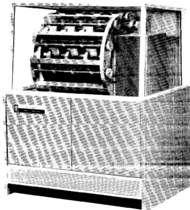
Figure 6-2. Flying Head Magnetic-Drum Unit
Magnetic Drum FH-880
The flying head magnetic-drum unit (see Figure 6-2) provides a large volume of random-access storage. Since the unit is word-addressable, the word transfer rate to the computer may be varied as desired by word-interlacing the data. Pertinent characteristics of the FH-880 are listed below:
Character capacity: 4,718,592 characters Word capacity: 786,432 words
Bit density: 490 bits per inch Access time:
Maximum: 34 milliseconds Average: 17 milliseconds
Magnetic Drum FH-SOO
This flying-head magnetic-drum unit pro-vides a medium amount of random-access storage with an access speed twice as fast as the FH-880. Because the unit is word-addressable, the word transfer rate to the computer may be varied as desired by the word-interlacing of the data. Pertinent op-erational characteristics of the FH-500 are listed below:
Character capacity: 1,572,864 characters Word capacity: 262,144 words
Bit density: 467 bits per inch Access time:
Maximum: 17 milliseconds Average: 8.5 milliseconds
Character transfer rate (maximum): 375kc Word transfer rate (maximum): 62.5kc Type of recording: RZ (return-to-zero)
MAGNETIC-TAPE SUBSYSTEM
A Magnetic-Tape Subsystem consists of a Magnetic-Tape Control Unit, a Uniservo power supply, and up to 12 Uniservo mag-netic-tape handlers. Three different Mag-netic-Tape Subsystems are available. These are:
Uniservo IIA (Remington Rand UNIVAC Format) Uniservo IIA (IBM Format)
Uniservo III
A Magnetic-Tape Subsystem performs the follo\ving operations:
Read forward or backward; write forward; search forward or backward on the first word read of a block; rewind and rewind with inter-lock.
Once an operation is initiated by the pro-gram, the Magnetic-Tape Control unit su-pervises the transfer of data between the selected magnetic-tape unit and core mem-ory without further intervention by the Central Computer. Character transfer rates of 12.5 kc, 20 kc, 25 kc, and 120 kc are available depending on the Magnetic-Tape Subsystem selected.
Additional general features of the Mag-netic-Tape Subsystems are:
Variable block length recording format. Detection of bad spots on tape (in RRU format). Parity checking on each tape frame.
The ability to check the tape handler functions.
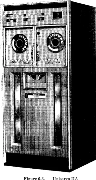
Figure 6-3. Uniservo IIA
Uniservo itA Subsystem (RRU Format)
character parity checks, and bad-spot de-tection are provided with this subsystem. General specifications of the Uniservo IIA unit are listed belo\v:
Tape speed: 100 inches per second Recording density: 125 or 250 bits per inch Interblock spacing: 1.05 inches
Character transfer rate: 12.5 or 25 kc
Tape length: 2400' plastic or 1500' metal tape Tape width: 0.5 inch
Type of recording: Return to zero
Uniservo IIA Subsystem (IBM Format)
This tape subsystem provides the 1107 Computer with the ability to read and re-cord on magnetic tape in the IBM 729-II Tape Format. A maximum of 12 Uniservo IIA tape handlers, modified for the IBM format, may be used with this subsystem. Only one tape unit may read or write at a given time, but any number of tape units may rewind while a read or write opera-tion is in process. Variable block-length format, character parity-checking, and start and end-of-block sensing are provided with this subsystem.
General specifications of the Uniservo IIA unit (lBlVi Format) are as follows:
Tape speed: 100 inches per second Recording density: 200 bits per inch Character transfer rate: 20kc Tape length: 2400' plastic tape Tape width: 0.498±.002 inch Type of recording: Non-return to zero
Uniservo III Subsystem
The Uniservo III high-performance tape handler provides the 1107 Computer with a 120kc character transfer rate tape sys-tem. Up to 12 Uniservo III tape handlers may be used with this tape system. To pro-vide increased flexibility this tape subsys-tem is capable of performing two read operations or a read and a write operation simultaneously. Two Uniservo III units may be read at the same time also. Two input and two output 1107 channels are used to provide this flexibility. TJp to 7 high-performance tape subsystems can be used on the 1107 Computer.
Other features of this subsystem are vari-able block-length recording, tape bad-spot detection, write-check mode of recording, and tape-frame parity-checking. Specifica-tions for the Uniservo III subsystem are:
Tape speed: 100 inches per second Recording density: 1,000 bits per inch Interblock spacing: 0.75 inches Character transfer rate: 120kc Tape length: 2400' plastic tape Tape width: 0.498±.002 inch
Type of recording: Pulse-phase modulation
Figure 6-4. High-Speed Printer
HIGH-SPEED PRINTER SUBSYSTEM
The High-Speed Printer subsystem consists of a Control Unit and one or two High-Speed Printers. The High-High-Speed Printer is under the complete control of the High-Speed Printer Control Unit performing whatever functions the latter demands of it. These functions include paper spacing of
o
to 63 lines, selection of one of the two units, and print. The control unit may alter-nately control either of two High-Speed Printers.Two models of the High-Speed Printer are available with the High-Speed Printer sub-system. They are the Model 46 and the Model 151 (see Figure 6-4). The Model 46 prints at a rate of 600 lines per minute and
has been used successfully by UNIVAC
with a printing rate of 700 lines per minute.
It is considerably smaller than conventional
High-Speed Printers. The characteristics of both the Model 46 High-Speed Printer and the Model 151 High-Speed Printer are reflected in the following specifications:
Line capacity: 128 characters (maximum) Available characters: 26 Alpha, 10 Numeric,
and 15 Special Characters
Number of carbons: At least 4 with 12 lb. stock Paper stock: Any standard sprocket-fed paper, 4-27 inches wide and up to card stock in weight
Horizontal spacing: 10 characters per inch Vertical spacing: 6 lines per inch, single-spaced
PUNCHED-CARD SUBSYSTEM
The Punched-Card Subsystem consists of a Punched-Card Control Unit, a Card-Reader, and a Card-Punch. Two subsystems are available, the Medium-Speed System and the High-Performance System. Either 90-column or 80-90-column equipment may be supplied with either subsystem. Supplied with the sUbsystem is a card buffer. This buffer allows concurrent operation of the Card-Reader and Card-Punch at the maxi-mum card-handling rates of the devices.
Once an operation is initiated by the pro-gram, the Punched-Card Control Unit su-pervises the transfer of data between the Reader and/or Punch and the Computer Core Memory without further intervention. Checking is provided in both the read and punch mode.
Medium-Performance Subsystem
In this subsystem, the card-reader brush-reads cards at two stations at a rate of 600 per minute. The second reading station is used as a checking station, and the unit has three output stackers. The card-punch for this subsystem block-punches cards at a rate of 150 cards per minute. A post-punch reading station is utilized for checking pur-poses. This punch has two output stackers.
High-Performance Subsystem
In this subsystem the cards are read by photocells in a dual sensing system at a rate of 700 cards per minute. Dual sensing is
utilized to provide a read-check operation. The punch used in this subsystem row-punches the cards at a rate of 300 cards per minute. Checking is accomplished by read-ing the card at a post-punch readread-ing sta-tion. This punch has two output stackers.
PAPER-TAPE SUBSYSTEM
There are two optional paper-tape subsys-tems available. One subsystem uses a one-character-per-computer-word transfer. The other subsystem utilizes the word assembly-disassembly features of the channel syn-chronizer. Control and operation of the former subsystem is discussed under the Supervisory Console section. The latter subsystem is discussed below. Either sub-system is capable of handling 5-, 6-, 7-, or 8-level paper tape.
The paper-tape subsystem consists of a paper-tape control unit and one or two paper-tape readers and punches (see Fig-ure 6-6). Odd or even parity-checking and generation are provided for seven and eight-level paper tape. Verification of all punched data is provided by a post-read station on the punch. Selection of parity and tape levels is provided at the reader and punch.
Paper-Tape Reader
The paper-tape reader is capable of reading up to eight channels at a rate of 400 frames per second. The unit may be operated in ei ther "start-stop" or "free-running" modes.
The unit will accept tape widths of lYt6 in.,
% in., or 1 in.
Optional paper-tape readers are available with operational speeds of over 1,000 frames per second.
Paper-Tape Punch
The Paper-Tape Punch is capable of perfor-ating up to eight channels at a rate of 110 frames per second. The unit will accept tape widths of 11IiG in., y'g in., or 1 in. A post-read
Optional paper tape punches are available with operational speeds of 300 frames per second.
MASS-STORAGE FILE SUBSYSTEM
A large random-access storage system will be incorporated in the 1107 system, provid-ing access time in the range of 100 milli-seconds, with a bit capacity of 600 million bits and a word transfer rate of approxi-mately 10,000 words per second. From one to eight mass-storage units may be attached
via a control unit to an input and output channel on the computer.
7. Systems Programming
The following programs will be provided for the 1107 Computer System:
ALGOL-An algorithmic language compiler.
The specifications are those developed jointly by the ACM Committee on Pro-gramming Languages and the G AMM*Com-mittee on Programming. The report was
published in the Communications of the
ACM, May and July, 1960.
FORTRAN -A translator which will accept problems written in FORTRAN language and translate them to a format which may then be processed. This will permit prob-lems previously coded in FORTRAN to be run on the 1107 without revision.
COBOL - A data-processing compiler. It is for programs stated in the English lan-guage of COBOL 1960-