THE UNIVAC SCIEh~IFIC GENERAL. PURPOSE" COMPurER SYS~
(MODEL 1103'.A) .
. PRELIMINARY INFORMATION·
1 December 1955
. . .
D!VIS\ON OF S~ERRY RAND CORPORATION
1. The thivae Seientif'ic GeDeral.Purpose Computer System (Jbdel 1103A)
2. Left Transa1t InstructIODI-CQmmand T1Il1ng
3. '!he t!l1vae Scientific Program Interrupt 4. !he thivac Scientific Magnetic Tape
storage System (Model 1103A)
5. Variable B10ck Length on the 1103A
thiservo '!'ape System
. 6. !he th1va.e Sclentl:t'le Inputjbutput Interlock System OIl lOA and lOB
7. 1he thlva.e Seientific storage of' I,oaA1ng lbut1nes
8. tIl1vae Peripheral Equipment tor Use with the l}Uvac SeIent1f1.c (Jibdel 1103A)
9 - The ·H1gh Speed Printer D1reetly Ccmnected to the 1I11vae Scientific
10. Exterual Function BIt Ass1snment
tor the thlvae Sctlentlf'1e(Jbdel U03A) 11. Punched Paper Tape Equipment tor use
with the Q11vae Seientlt1c
MODEL 1103A
THE UNIVAC SCIENTIFIC
GENERAL PURPOSE COMPUfER SYSTEM
(MODEL 1103A)
GE~cRAL DESCRIPTION
. The Model Il03A is a general-purpose di'gital computing system for applica-tions requiring large storage capacity, high operating speed, and programming versatility. Its internal memory consists of 16,384, registers of magnetic drUm storage, 4,096, 8,192, or 12,288 registers of magnetic core storage, and
.the A and Q registers. Each of these registers is individually addressed and
directly accessible. Supplementary storage is provided
by
up to ten Oniservo magnetic tape.units.Standard input and output equipments used with the computer consist of a photoelectric paper tape reader, a typewriter, and a high-speed paper tape punch. Communication with a wide vari~ty of optional devices is made possible by llse of an eight-bit input-output register, lOA, and a 36-bit input-output
register, lOB. The choice of optional equipment is determined by the user~s
needs. Frequently included are: Univac magnetic tape units, a card reader and card punch. a line printer, and an oscilloscope display unit. Directly connected devices may also include: Teletype communication circuits, analog-to-digital converters (for use with sensing instrumentation), signal circuits to process-actuating mechanisms, etc. The computer's input-output system per-mits simultaneous· use of several external units and allows computation to pro-ceed while such terminal equipments are operaUlng. The use of Unitapes permits off-line processing of information by a variety of Univa~ auxiliary equipment ••
The computer performs 41 different arithmetic and logical operations. It is fully automatic in that the sequence of operations is determined by a pro-gram of internally stored instructions capable of self-modification. During
.the performance of the program, instructions are removed from storage, o'ne 'at
a time', in the order required. , To attain high computational speed, the com-puter operates in the parallel mode; i;e., all digits of a number are operated upon simultaneous ly. Internal arithmetic operations a.re in the binary number system. The basic word size is 36 binary digits, or "bits". A word
may
be aninstruction, a number, or an arbitrarily coded quantity.
A form of "two-address" logic is employed. An instruction word consists of a 6-bit operation code and two IS-bit execution addresses. The functions . of the execution addresses are different for the various types of instructions t
but, in general, they specify registers in the memory from which operands are obtained or in which results are stored.
SCIENTIFIC
THE ON IV AC UI'ER SYSTEM
.,.~
,,I'f'" -'~'-'i~1
·f
,J
'r. >~ .. _
MODEL 1103A
bit of a number is "0", the number is said to be positive; if the left-most bit is a Itl"; the number is said to be negative. In-the oneQs complement
system, a negative number can be obtained from a positive number by complement-ing--all the bits (including the sign bit) of the corresponding positive number. In the single~length, or 36-bit, register. integers from 1_235 up to 235-1 may be represented; in the double-length. or 72-bit, Accumulator integers from 1_271 up to 271=1 may be represented. In the oneQs complement notation, each of the integers has a unique representation wiih the exception of zero; zero has both a pbsitive and negative notation; however, because of the nature of the arithmetic circuIts, a negative zeio cannot be generated as the result of arithmetic operations.
Integers not lying in the above range, as well as fractional quantities, can also be handled by suitably scaling such quantities so that the resulting quanti ty can be represented by machine numbers.
cabinet.-MODEL 1103A
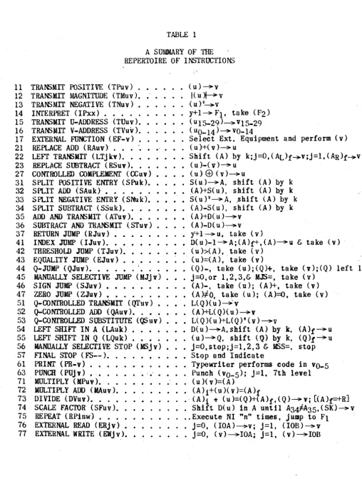
REPERTOIRE OF INSTRUCTIONS
The complete list of instructions which the computer performs is presented below. The instructionsar~ arranged in 11 groups according to their basic characteristics. In each listing a eode representing the instruction is en-closed in parenthesis after the name of the instruction. The operation code portion is designated by a two-number combination and the execution addresses by the letters u and v. In some cases u is replaced by the conditioning fac-tors j, 0, or k, as in the Repeat instruction or the Left Transmit instruction. In other cases v is replaced either by the repeat termination address, W, or in some Shifting operations by the factor k. The repertoire of instructions is summarized in Table 1. To more fully comprehend the meaning of the symbols contained in the repertoire the following,glossary of terms and abbreviations is given.
Word.
Instruction.
Operation Code.
u. v. operand. ( ). A. Q.
x.
-A combination of 36 bits.
- A word, represented by i3S, i34, ... , iOr which causes the computer
to
perform one or more of its operations. The instruction consists of an operation code and,usually, t\lfO execution addresses.
- That six-bit part of an instruction. represented by i35, i34 ••.• , i30. designating the operation to be performed.
- The first execution address of an instruction, repre-sented by i29, 128, .•. t i15.
• The second execution address of an instruction, repre-sented by i 14. i13, ... , iO.
- A word on which an operation is performed.
- Parenthesis, denoting "the contents of"
" The 12-bit Accumulator, A71, A70, ••• , A70.
- The left-hand (most significant) 36 bits of A.
- The right-hand (least significant) 36 bits of A.
- A 36-bit shifting register, Q35,
034.
....
Qo-- AQo--36Qo--bit exchange register, X35. X34,
....
O( u).
S( u).
L(Q)(u).
j.
n.
k.
F2-F3· TWR.
HPR.
CI.
NI.
MODEL Il03A
- The final contents of a register after an operation has taken place.
- A 72-bit word whose right-hand 36 bits are (u) and whose hand 36 bits are all alike and equal to the left-most bit of (uL
- A 72-bit word whose right-hand 36 bits are (u) and whose left-hand 36 bits are all zero.
- A 72-bi t word whose left-ha-nd 36 hits are zeros and each of whose r'ight-hand 36 bits is given by the product of the corresponding bits of tu) and (Q)~
- A 72-bit word whose left-hand 36 bits are zeros and each of whose rIght-hand 36 bits is given by the product of the corresponding bi ts of (v) and the com~lement of (Q L
... A one-digit octal number, represented by u14, u13. u12.
- A four-digit octal number, represented by uII, uIO, ..• ,
uo.
- The shift count, usually represented by V6, v5, ... , VOl
but in the Left Transmit instruction, represented by
~6t U5, ••• ,
uo-- Fixed octal address 00000 (or address 40001 if so manually selected in the test mode).
- Fixed octa 1 address 00001. - Fixed octal address 00002.
- A typewriter register of six bits.
- The high-speed punch register of seven bits.
• The current instruction.
11 12 13 14 15 16 17 21 22 23 27 31 32 33 34 35 36 37 41 42 43 44 45 46 47 51 52 53 54 55 56 57 61 63 71 72 73 74 75 76 71
MODEL 1103A
TABLE 1
A SUMMARY OF THE REPERTOIRE OF INSTRUCTIONS
TRANSMIT POSITIVE (TPuv) • • •• (u) ~ v TRANSMIT MAGNITUDE (TMuv). • I{ u ~ v
TRANSMIT NEGATIVE (TNuv) • (u) II~V
INrERPRET (IPxx) • • • • • y+ 1 ~ F1 t ta ke (F2)
TRANSMIT O-AOORESS (TUuv). (u 15-29)~ v15-29
TRAr6MIT V-ADDRESS (TVuv). • • (uO_14)~vO-14
EXTERNAL FUNCTION (EF-v) • • • Se 1eet Ext. Equ1pment and perform (v) REPLACE ADD (RAuv) • • • '. (u)+(v)~u
LEFT TRANSMIT (LTjkv). • • • • • Shift (A) by k;j~O,(AL)f~v;j=l,(AR)f~v
REPLACE SUBTRACT (RSuv). •• • • (u )-( v ) ~ u CONTROLLFD COMPLEMENT (CCuv) • • (u) Ef) (v )~U
SPLIT POSITIVE ENTRY (SPuk). •• S(u)~A. shift (Al by k SPLIT ADD (SAuk) • • • • • • (A}+S{u). shift (A) by k SPLIT NEGATIVE ENTRY (SNuk). • S(UP~Af ,shift (A) by k SPLIT SUBTRACT (SSuk). • • • • (A)-S( u). shift (A) 'by k
ADD AND TRAr6I4IT (ATuv). • • (A)+D( u)~v
SUBTRACl' AND TRANSMIT (Sfuv) • (A)-D(u)~v
RETURN JUMP (RJuv) • • • • y+l~ut take (v)
INDEX JUMP (IJuv). • • • • • • • D(u)-l~A;(A)r+,(A)~u & take (v) , THRESHOLD JUMP (TJuv) • • • • • • • • (u»(A), take (v)
EQUALITY JUMP (EJuv) • • • • (u }=(A), 'take (v)
Q-JUMP (QJuv) • • • • • • I • • • • • • (Q) ... , take (u);(Q)+, take (v);(Q) left 1 MANUALLY SELECTIVE JUMP (MJjv) • J=O,or 1,2,3,& MJS=, take (v)
SIGN JUMP (SJuv) • • • • • • • • (A)-, take (u); (A)+. take (v) ZERO JUMP (ZJuv) • .; • • • • ,. • (A
>*0.
ta¥:e (u); (A)=Q t take (v)Q-CONrROLLED TRANSMIT (f1l'uv) .. • L( Q)( u)~' v Q-CONTROLLED ADD {QAuv} • . • • _ (A)+L(Q){u)~v
Q-CONfROLLED SUBSTITtrrE (QSuv) • • • L( Q)( u )+L(Q)' (v) ~v
LEFT SHIFT IN A (LAu"k) . . . D(u)~Atshift (A) by k, (A)f~u LEFT SHIFT IN Q (LQuk) • • • • • • • (u)~Q, shift (Q) by k, (Q)f~u
MANUALLY SELECTIVE STOP (MSjv) • j=O,stop;j=1.2,3 & HSS=. stop FINAL STOP (F'S--); . • • • f . • Stop and Indicate
PRINT (PR .... v) . ~ • • . • • • • • . • Typewri tar' performs code in vO-5 PUNCH (PUJv) • • • . • • • ,.' • • • • Punch (vO-5): j=1,'1th level 'MULTIPLY (MPuv,). . • • • • • • • (u)(v)=(A)
MULTIPLY ADD (MAuv). • • • • (A) i+( u)( v )=(A}f
DIVIDE (DVuv). • • • • • • • . • ' (A)i -t (u)=(Q)+(A)ff(Q)~Y; [(A)r-+RJ
SC.ALE FACfOR (SFuvL, • • • • Shift D(u) in A until A34tfA35,(SK)~v REPEAT (RPinw) • • • • •. Execute NI "n" times, jump to F1 ' EXTERNAL READ (ERjv) • • j=O, (IOA)~v; j==l, (IOB)~v
MODEL 1103A
REPERTOIRE OF INSTRUCTIONS
SEQUENCED INSTRUCTIONS
1. MULTIPLY (71uv): Form irt A the 72-bit product of (u) and (v), leaving in Q the multiplier (u).
2. MULTIPLY ADD (72uv)~ Add to (A) the 72-bit product of (u) and (v), leaving in Q the multiplier (u).
3. DIVIDE (73uv)~ Divide the 72-bit number (A) by (u), putting the
quo-tient in Q, and leaving in A a non-negative remainder R. Then replace (v) by (Q). The quotient and remainder are defined by: (A)i = (u) . (Q) + R, where
o
~ R.s I( u)l. .Here (A)i den.otes the initial contents of A.4. SCALE FACTOR (74uv): Replace (A) with D(u). Then left circular shift fA) by 36 places. Then continue to shift (A) until A34 "# A35. Then replace the right-hand 15 bits 'of (v) with the number of left circular shifts, k, which would be necessary to return (A) to its original position. If (A) is all ones or zeros, k = 37. If u is the address of the Accumulator, (A) is left unchanged in the first step,' instead of being replaced by D(AR L
5. REPEAT (75jnw): This instruction taIls for the next instruction, which
will be called NIuv, to be executed n times, its "uti and "vtt
addresses being
modified or not according to the value of j.' Normally n executions are made and th~ program is continued by ~he execution of the instruction stored at a fixed Me address Fl. The steps carried out are:
a. Replace the right ... hand 15 bits of (Fl) with the address w.
, b. ,Execute N~u,; the next instruction in the program n times.
c. If . , J = 0, do not change u and v.
If j = I, add one to v after each execution.
If j :::: 2, add one to u after each execution.
If j =. 3, add one to u and v after each execution.
d. On completing n executions, take (Fl)
as
the next instruction.e. If the repeated instruction is a jump of stop instruction, the
occurrence of a jump or stop terminates the repetition. In additiQn,
MODEL l103A
TRANSMISSIVE INSTRUCTIONS
1. TRANSMIT"POSITI\~ (lluv)~ Replace (v) with (u).
2. TRAl'SMIT NEGATIVE (13uv)~ Replace (v) with the complement of (u).
3". TRANSMIT MAGNITUDE (12uv): "Replace (v) wi th the absolute magni tude
of (u).
"4. TRANSMIT U-ADDRESS (15uv): Replace the 15 bits of tv), designated by
vIS through v29, with the corresponding bits of (u), leaving the remaining 21 bits of (v) undisturbed.
5. TRANSMIT V-ADDRESS (l6uv); Replace the right-hand 15 bi t8 of (v) designated by vO through v14, with the corresponding bits of (u), leaving the remaining 21 bits of (v) undisturbed.
6. LEFT TRANSMIT (22j kv) ~ Left circular" shift (A) by k places. Then re'"
place (v) with (AL) if j = 0, or replace (v) "with (AR) if j" = L
7. ADD AND TRANSMIT (35uv): Add D(u) to (A). Then replace (v) with (AR). 8. SUBTRACT AND TRANSMIT (36uv): Subtract D(u) from"(A). Then replace
(v) with (ARlo
Q-CQNTROLLED Il'5TROCTIONS
1. Q-CONrROLLED TRANSMIT (51uv): Forr;t in A the number L(Q)~u). Then
replace (v) by (AR). ....
2. Q-CONTROLLED ADD (52uv): Add to
(Ar
the number L(Q)(u). Then replace(v) by (ARL
3. Q-CONrROLLED SUBSTITUTE: (53uv): Form in A the quantity L( Q)( u) plus L(Q)q(v). Then replace (v) with (AR). The effect "is to replace selected bits
of (v) with the corresponding bits of (u) in those places corresponding to
1 ~ s in Q. "
REPLACE INSTRUCfIONS
1. REPLACE ADD (21uv) ~ Form in A the sum of D(u) and D( v>. Then replace: ( u) wi th (AR).
2. REPLACE SUBTRACT (23uv): Form in A the difference D(u) minus D(v). Then replace (u) wiih (AR).
3.CONTROLLED COMPLEMENT (27uv)~ Replace (AR) with (u) leaving (AL) un~
disturbed. Then complement those bits of (AR) that correspond to ones in (v).
IDDEL l103A
4. LEFT SHIFf IN A (54uk): Replace (A) with· D(u.). Then left circular shift CA) by k places. Then replace Cu) with (AR). If u is the address of the
Accumulator, the first step is omi~ted, so that the initial content of A is shifted.
5. LEFT SHIFT IN Q CS5uk): Replace (Q) with (u). Then left circular shift <Q) by k places. Then replace (u) with (Q).
SPLIT INSTRUCTIONS
1. SPLIT fUSITIVE ENTRY (31uk): Form S(u) in A. Then left circular shift CA) by k places~
2. SPLIT NEGATIVE ENl'RY (33uk): Form in A the complement of S( u). Then left circular shift CA) by k places.
3. SPLIT ADD C32uk): Add S(u) to (A). Then left circular shift. (A) by
k places.
4. SPLIT SUBTRACT (34uk): Subtract S(u) from«A). Then left circular
shift CA) by k places.
TWO-WAY CONDITIONAL JUMP IN3TRUCTIONS
1. SIGN JUMP (46uv): If A71 = 1, take (u) as NI. If A71 = 0, take '( v) as NI.
2. ZERO JUMP (47uv)~ If (A) is not zero, take (u) as NI. If (A) is zero,
take (v) as NI.
3. Q-JUMP (44uv)~ If
035
= 1, take (u) as NI. If Q35 = 0, take Cv) as NI. Then, in either case, left circular shift (Q) by one place.ONE-WAY CONDITIONAL JUMP INSTRUCTIONS
1. INDEX JUMP (41uv): Form in A the difference DCu) minus 1. Then if A71 = 1, continue the .present sequence of-instructions; if A71 = 0, replace
( u) wi th CAR} and take (v) as N J . ·
2. THRESHOLD JUMP (42uv): If D(u) is greater than (A), take (v) as NI; if not, continue the present sequence. In eiiher caser leave (A) in its initial state.
3. EQUALITY JUMP (43uv): If D(u) equals (A)1 take (v) as NI; if not, continue the present sequence. In either case leave CA) in its initial state.
ONE-WAY UNCONDITIONAL JUMP INSTRUCTIONS
MODEL 1103A
2. RETURN JUMP (37uv): Let y represent the address from which CI was ob-tained. Replace the right-ha~d 15 bits of Cu) with the quantity y plus 1.
Then take (v) as NI.
3. INTERPRET (14--): Let Y represent the address from which CI waS
obtained. Replace the right-hand 15 bits of CFl) with the quantity Y plus 1. Than take (F2) as NI.
STOP INSTRUCTIONS
1. MANUALLY SELECTIVE STOP (S6jv): If j
=
0, stop computer operation and pro·vide suitable indication. IfJ
= 1, 2, or 3 and the correspondingly num-bered ~ selecting swi teh is set to ttstop'\ stop computer operation and provide suitable indication. Whether or not a stop occurs, (v) is NI.2~ FINAL STOP (57 .. -): Stop computer operat ion and provide sui table indication.
EXTERNAL EQUIPMENT INSTRUCTIONS
1. EXTERNAL FUNCTIONS (17-v)~ As designated by (v) select a unit of external equipment ·and cause it to perform a function.
" I
2. EXTERNAL READ (76Jv)~ If j = 0, replace the right-band 8 bits of (v) wifh (IDA); if j = 1, replace (v) with (lOB).
3. EXTERNAL WRITE (77jv): If j = 0, replace (lOA) with the right-hand
8 bits of (v); if j = 1, replace (lOB) with (v). Cause the previously selected uni t to respond to the information in lOA or lOa..
4. PRINT (61-v); Replace (TWR) with the right-hand 6 bits of (vL Cause
the typewriter to perform the operation specified by the 6-bit code.
. .
MODEL 1103A
ADDRESS STROCTURE
The standard address structure for the 1103A. is as· follows:
Addresses in Octal NotatiQn
00000 - 07777
10000 - 17777 20000 -27777 31000 - 31777
32000 - 37777 40000 - 77777
Storage Class
Magnetic Core (1st bank, 4096 Registers) Magnetic Core (2nd bank, 4096 Registers) Magnetic Core (3rd bank, 4096 Registers) Q-Register
Accumulator
Magnetic Drum (16,384 Registers)
This is in contrast to the address structure which is standard for the Model 1103 which is as follows:
Addresses in Octal Notation
00000 - 01777
10000 - 17777
20000 - 27777 30000 - 37777
40000 - 47777
Storage Class
Magnetic Core (1024 Registers) Q-Register
Accumulator Unused
Magnetic Drum (16,384 Registers)
MODEL 1103A
INSTRUCTION EXECUTION TIMES
The following table contains execution times for the non-repeated Instruc-tions in the Model 1103A computer. In each case the instruction references are to the magnetic core storage. The times are given in microseconds.
With the exception of the Threshold Jump (42uv) and the Equality Jump (43uv) instructions, the execution times for repeated instructions can be de~ermined by subtracting 14 microseconds from the non-repeated execution times with·the ex-ception of the last execution of the repeated instruction which takes the non-· .repeated duratlon~ For example~
) 75J nw (Repeat)
Ilu v (Tra nsm! t Pos 1 t i ve )
The execution times for the Repeat and Transmit Positive instructions are 42 microseconds and 40 microseconds respectively. The execution time for a repeated Transmit Positive is therefore 26 microseconds (40 microseconds minus
14 microseconds). The total time, therefore, is the sum of the times: .
42 + (n"!'"l) 26 + 40 microseconds, or the Repeat' time plus·n-l repeated Transmit Positive times plus a non-repeated Transmit Positive time. This expression may be reduced to 56 + 26n micr9seconds.
INSTRUCTION ,7' lluv 12uv 13uv 14--15uv 16uv 17-v 21uv 22kv 23uv 27uv
-31uk 32uk 33uk 34uk 35uv 36uv 37uv'
41uv ... Jump 41uv-No J.
42uv-Jump
42uv~No: J.
43uv-Jump 43uv-No. J. 44uv
45jv-.Jump
. lV_
45.). No 46jv
41uv
lVDDEL 1103A
INSTRUCTION EXECUTION TIME MC TO MC
MICRQSECOmS INSTRUCTION MICROSECONDS
-40 42 40 34 40 40 32 66 34+2k 68 58 34+2k 34+2k 36+2k -36+2k 48 50 38 58 48 46 46 58 58 20 20 ? _0 20 32SIuv 48
52uv 50
53uv ,80
54uk 48+2k
55uk 46+2k
56j v-Stop 4
56j v-No S 20
1.
2.
51-- 2
61jv 38 (note 1)
63jv 38 (note 2)
71uv 122+10(ul35 + 8 ~; (ull
35 72uv 194+10(u)35 + 8
2:,
(u)i0
73uv .. Ma.x. 486 + .8(A)71
73uv-Min. 480 + 8(A)71 74jv 124 +'t(note 3)
75jnw 42 + Rn + P (note 4)
76jv 32 (note 5)
77j v 32 (note 5)
Plus a lockout· time. of lOSms for
successive prints.
Plus a lockout time of 16.6ms for successive punches.
3. Where r~ 2 [36-k (mod 72)] and k is , the seale factor:
°
~ k ~ 71. Fork =37. use value for k = 38.
4. Where P
=
time for'jump to Fl ~ndRn
=
execution time of' repeated in-struction; if n=
0, ,Rn=
O.THE UNIVAC SCIENTIFIC
LEFr TRANSMIT INSTRUCTION COMMAND TIMING
1
December1955
D1 VISION OF SPERRY RAND CORPORATION
UNIVAC SCIENTIFIC
Instruction: Left Transmit (LTjkv) OPERATION CODE: 22
Left circular shift (A) by k places. Then replace (v)
with (AL) if
J
=
0; or replace (v) with (An) if j =1.MP
C{)AMANO SOURCE0 Clear X CTC-AR
Transmit UAK to SAR CTC-PCR
1 Initiate Shift A CTC-SKC
\
Wait Internal Reference (See Note) CTC-POC
2 If j
=
0 If j = 1Transmi t (AL) to X Transmi t (AR) to X CTC-AR
Clear SAR Clear SAR CTC-SAR
5 Transmit
VAK
to;SAR CTG-PeRInitiate Write 0-35 CTC-SCC
Wait Internal Ref'r n e e e e eTC-POC
Note: No wait is generated if uk" is zero.
DEST
X
UAK
SKC
PDC
-A
SAR
VAK
sec
THE UNIVAC SCIENTIFIC
PROGRAM INTERRUPT
1 .. December 1955.
DIVISION OF SPERRY RAND CORPORATION
$NCINEEIINC
~SEARCH
,fsSOCIATES DIVISION'11$ tlJiIIV~ SCIENtIfIC
PROGIWt
INfaRurr
, TIle, FlO,'" ram illter,r, .pt, P, eratts,'extern,' 1," 8qllipm8,nt to au.t:~tl, Qa111 interrupt a· P'tOVram wJtentlle equlpmeut II read, to, cOIIII1lJlleat.e with t1le·t . . pllter,a ,The :
.
c~uter,"pon
receiptotalt
i.lIterrupt signal tcompletes
th current In.trac-'tloll and Pl'oettre.t~~xt i.tr'"'tJ9D!r~ ,tbeJIXtil addres.Fa-
No1'll8111FscolttaiJ1S8 Return Jump iutractloJl ldtleh t1811Se$ a returltio tbe .111
pro-'gram
ait&T
&XeeutloD ,of, .ome Jl(b .. olltln&.Dsuallysllch a subr,()uti" will,pro-~tde for trlPSfel' of illformatiefl between tile colllptiter end tile Inte,:ruptlng
eqt.:lpment.
, ',-, In tbe case, of free . ruOillfJ extarlull equipment sucb. as tile punched card equipment aDd the 11~eprlftter lIJ'eof tbtprogratall1t..errfitpt perm ts maximull computation betweea transfers Of iidtJrmatiolf. Tetadiu~l equipment requiring sporadic iapn/ontpll't l1I81 operate in tlte interrupt DlOde so as to free the c·o. ptlter to exec'llteotker Pt'OQrald wilen not-~.ees.lng iufofmatlon for the inter-rupting equipment. A p.$'h~tolt on the colrtrol eons'ole is available for man ...
ual
interruptionof
aprogram.
A computer operation cOD81s~ts of t.wo paJ'ts g
Part One - the execution
ot
th.e current instruction. Part Two - the acquisition of the next InttruGtloll.At the start .of Part One, the Provram Control Registers already oGnt.aintbe current instt"Jotion 8S a tesllit of the second pert of the pHViollsoperation, and the coot.ents of the P,"oyram Address Couoter:J$:"1+1. where· y 1s tile address ire. whicb the Cllr'reat instruction fts obtained. Uale"s . tbe curreat t'nstrllc- . tloa change. til. Cf)utents of the Program Address Counter, the next:· iutnetion . will be obtained from addres$ '1+1.
Thus, 1n
a normal prQ9ram Seq_DOO sue ... ,e-es.ive instructions are obtatlledfromcolSeCQtl-,.e addresses.
A computer operation is ef(ee-ted by a" series of wired-In co_ends. Durio9
8D operation from one to eigbt Main p~ls.e. are gelt.erat,fld, the n~r .of
"in
.PUls,e$· being eOftll1euutat.e .JAt.h t:ke llWDber o'! llon-si_lt'aaeou .cOIIIlUlDds r·e'"
MAI!
f.!!LtiE
lIP 6
COIUtANlS
Trallstdt tlte contents of the ProgrtlDi
A4dress 'C;,ollnt.er to the storage Addres.lleglster . ,
Advallce tbe Program AddreSs COtluter InJ\late Read (read tile contents of
tJu~ address in the St.orageAddrell Regista·r anfl
transmit these
con-tens to tlte ·X-Register)MP7
TnlsDdt tlleeontellts Q:f the. X-Register' 'to .the Program COII'trol Regis~ers. Tku$as the follmJt9 MP 0 is is,sued the execu.tlon of thelext in$tnctiolt , begins .•
However. if the interrupt is activatedduriDf the· execQtion of alf instruc-tion, s'a "interrUpt" signal changes the
series
of ctJmrlaads issued on liP '6.IlAINPU
MP 6'
C_1I)5
Set tile 5t.rag.Address Register to
fixed address F3. ;:
00002.
Initiate Read '(read the 'contents of
addre.sF3 and transmit
'these contents to the X-Retlster) ,Tbereare 110 cballges in the MP 7 commaada. It should be Doted that the Prop-am Ad4.iress
Counter
still contains the address of the nextprograM
in-struction; thJ;s address will be placed in storage by the eQClttionof a Return Jump InstructloB st.ored at address '3- ' The It-addre.s of the Return Jullp . . ' instru.ction spec~fles ,whereiAthecoD.tlJltJ of the, 1;'0,Irrlll, Address cotmte·r ar~
to be J·tored lor .f\ltute ref
ttteac., ,
and, t,beV-addres •. of the Return: Jutpfa-structloD specifies tbe. startlDfaddre,ssof the'trb1:oatllle 'to be used itl. oper-atllJ9 tile IJlterruptlnv ext.rJ&lil equ~ptDe ••
'fbe program !uterxuptlsactivated-by, :,,' si,oal Oft an iaterrupt line ill the computer. TJals
st.gul ..,
or-t,tnate
in lnyext8l'1l81 equlpment8ats06yer.The're
1s
also' 8D: Dt.rElROPT P.sJabutton 08 tile SUpt!rvisoryCe.,rol,
Panel
t~'etl1erwith an INrERRUP.t KNAIt.i..awi'tcll and EXABLE lJI):tCATOI. ,With
thla
,IWfEBRt1PT button Q progTant . , be'.rulall,.
Internpl,edby
an operator. 'tllDEL .110M
, f"eaturet the external' eqttlpJDlt,a\allt,Ci.ticall, Interrupt.Jtheprooru _en ·St
, 1,
,ready to communicatewitb
tbecapt4ir. T&tuI tlltl profl1lDlller neednot
,c*e-,
hlly
deterDdne t'lle division" otco!lpU:tei: tUie ~.'l'r oomp,.tlnQ operations ·aJk1 exttreat operat lou.. ' , '
At the t1_ t~ exteraa lequlpraent ls read,. to transfer information be- ' 'tween itself 81ldtlte cQaJPut.etr, a subroutine Is initiated .IlGse' purpose 1$ to
obtain sword troltl storage or 'to place: a ,WON ill~o
stotap.
The ivbroutino' mUstbe
c.ompletedin
8 spuified time called tbe "rf14)ept.i,e ti . . " 0,£ thetree-rUlUling external eqllpment. FQr iitstance, tbe receptive time of tllepunclted card equipment is 1.5 mil11seco-nd.s for 8 punu11lf ope"atlon ·and 10 rnililseeo~~
tor a r«tading operation. As all alto.tic precaution again.t errors arisill9 " from programs which violet .• tiles. restrlct10Ds t 8 .. 10, 'AULT oeears. '
In the case -of extenaleq1tipment wltha limited ~eept ive time, restric-tl085 are iBIPosed on (a) 'tile length of time ,it takes the computer to execute, _ the sabroQtinewhich ptocesses IDlo~tloD
tor
the interrupting equipmen,t' and:-': (b) the lentllta,.t
t1_1t., takes the C01IIp1tf,er to ,fluish ,executing the, current: . i.strvetioaaad1.,ue
MP6~' -The laterrestriction
.111 in Jl81!Jeases
preCllude;retereneest,o
t.
ma,~etJc drum since it 'urq. takltas.
long 8s;34 mil1iaeeolJds to aeces. a· dr"4t1d~t!S'.. ·Sim.tl8l'l". the'Qe
ot,
the' 'Repeat i h.tl'llctioD 1. lillf1ted. Fot' :{~ tlle 'B$t.~~u;t",n ~illU ex~ed at -the: time til., external, equl~.t ls~e'adf'
to
cOmmtUI!fate Is arepeat.ed illStructi()n. AlP 6 Is btpassed. • . 0111, ' . 0 -th. Repeat seq.ueha! ~Il coaapleted and lIP 6 is lSlued duriritJ exe;'"etrtioDof tho jW&1p instruction In '1 will tJht prograAI be interrupted.
USE FOR ,IJfrEUmANr . INPUT
It is evident that the propUl interrupt facilitates spo,ad~~ Input from either on-line equip_nt, O~ hiih priority prQbleetS wltic.Jt'demand ia;pediate access to the computer. ' The routines for'i'lell . , be'store4 in tbecomputer
melllOry at all times and. entered by .8111 oftlte prOgramlnt,err-lIpt.. Such, tOlitine may initially store the status quo of the 1,terrvpted program. Later,
tke interrupte4
program
may
berestored and the,cQ"!'aterwill restl.lle executing
tbat program, at tile point ofintertuption. TIle, pr.~.iJtte~ruptIl81~lso, beused to!flcil1~at. "baiting pa .
..-_tersln
a progt.,\Vk1ell is being exec~ted bl the cOfJlptlter. Fa:r 11lJ~a.e. if. it i. desil"ed toadJ
\tIt $ }.l~ram on the b,s!.THE UNIVAC SCIENTIFIC MAGIETIC TAPE STORAGE SYSTEM
(MODEL 1103A)
1 December 1955
O:ViSiON OF SPERPY RAND CORPOR1\T!Or>;
THEora VAe SClENrI FIC . : MAG1IETIO 'UPlSTORAGE SYSTEM
GEftiaAL DESCRIPTION
The Magftet~tc~Tape. Storage Sl.stem of the Model.l10M Computer System co.. . prises a number' of Untaer'YO tape haltdliJlI saeclunl1slIS,wltieh ~re located .exter": nally to tbe c~puter.
8"
aD electl"onic oontrol see-tlon _ielt is' leeated within the compliter atrlW-t)lre. The n1.U1lber ofhl.servos
ItseQ 1$ optional upto a maxillRlm
or
ten funotlOnaluBits. . B, ~aas of DJaDual seleetions the tUdt designatioB$may
beassigned. In
any
.1Uler totae
functional 1I.nits. Use of tile Dniservo u.llits ma.ke:S.po.sible off~.li.ne proee$si.n.g of infol'iftatl0.n by a· variety of Univac periphoralequipments.· .
TAPE CflARACTERISTICS
Eioht-chan~l recording is employed with the Unitapes;
$ix
cbabnels 0011-· tain data. onecnannel" contains a parity ehetk bit on the six, dataehannels,and olle channel 1s usa4 toreeord ,8 sprocket ,or 'timing, sivnal.
. Information. is rec.9rded 1n blocks of 720 bexablt characters Qr' lines OD the t8,." e.a:ehblock thas"'"coll~allliJ1g 129. cOIllplete 36 bit eOIllP"ter words. A · recctrding d~ns.ity of 128 lines per in~n Is standard. Tbe blocks ate normally
s_,.rated by·~ ."dead" $paee of one' i.neb Oft the t8pe~ Up to 325.000 eOmp\l1.er
words may be stored OD a standard·l5OQ..foot reel of tape.
To provide. tapes which ~an be u.sed with all the Uni vae aui lla~ equi po-Il8Jtt8. several optionalJ:'eeotdlng formats can be se,lected by, progrllmcofttrol. Optl,cuull selections incl"lde an interbloek space of .2.4 inches ~nd 8. s·ttbdlvision of a block into six blockettes each cQ:Dtaining 120 hexabit ebaraeters and. having a one-inch. ~ne-te"tb-lJlch, or zero $Pacil1Q between bloekettes. In .' addition, an op!ional recordiniJ densit10f 50 lines per ineh is ,pex.ls.sibl.~~
The magn!:tie tape is alb1' stopped in the "dead" space betWeen blocks. A block of luiorll8t1011 i6 recofniz.ed by MaDS of the ti.lJlg~ig,n,eli .. The .end . of a block is detected '1)1' ,a tijdng device. actuated ill tbe last bloekette~ wIl~eh signifies the end
of the
block if the interval betweentilJling.
51«n81. $xceed:sa eettain length of time.SEtECTIOHAND '!. . INSTRUCTION . ' c," COJttROL
The ExterrtalFunetion IDstr.~tio8
(17 ... ")
t.
used to i~nitlate t.he various reading. wrltlno. and posittoniD(jope:ratiOriS 8f'the Uniservos through t'll. Selection and' Ins t rUGt ion Control portion ,of tbe • .,lt~ctroDic cQntl"_olsectioJl. Coded information provid~d ,b,the Extertt.lFuDetlon Instr\leti'on 'i .• eludes t ••following: (IY desiSJllatioliof the s~lec~&d UnlservQ, :(2) type oC:tecordlq format, 1. e. · ... whicb bloc"k.'alidblockott'.spaciny is to be IIsed and which r:e- . , :cording pulse deBsity' is' io
be'·.'.d,.a.m
'<3) type o'f tape. operatloll tobe,per-,.'':'f o r m e d . ' . ' "
TA~E OPERATIOrf)
An ExtEn::J1~l Function illSt~uetion is programmed to initiate a tape ·o.peta- . tion. 11'1. the,C8$e ofax:~.ad1.DI orwritllli op&tation, the Exteznal FllaetloR, 'iniitaetion whiCh in! tiates tile o·peration QIltst be' fOllowed by
an
appro priat.eIUJlDber' of E~ernal Read (76Jv) or External1rite (77j Y) instrllctioDS ,to tratiS~
fe,x- the information between, the Inplt/Outpvt Heoister. .1 . : . and the CODlptltermemOry~ • • .
1.' REAQ'fQRIABD ... R~ad dat.sfr()1Z1 tl\e ma~t1"~" tape, as.sEMilble.into 36-blt e01QPute't word •• and tra'nsfer the words to the'Compater, Input/Output Register,.
1 0 0 . , . , "
The
iQitiation of this operation C1Iu~~s'tlle deslgJJated,Uniservo to read a number of blocks :from tbe tape. The~e&(llD' operation must be terQlinated by a "Stoptf External Function instructio~ which is pyogrammed i»aedlately' followinv the ExWrllal Bead' instruction Q,sed to read the last word' in the ,fInal block .. " If,it is desired to read,o'ne' bl~ek only, the ttSto~tt code Is , .. included in the "Read Forward" !xterttal 'lulctlon instt'llction ,wlncb p-reoed_s
the 120 Ext~rnal!ead iD$tru~tlCJns. '
2. WRl~FORWARD. - TrBasf-er word. fro. the c011tPuter InpatlOu\put Register, lOB, and re~()rd,.c)J1 the Unlservo tape lJtsixsegments 01 six bi t.,s aacll.
The init.iation of tbisopel'ationeauiea the Urdsarvo to write Cl ftudlber of bloc'ks on. th~:·t_pe aDd the writing RiuS~: 'he terminated by a "St6ptO E~ei-R&l
FUQ~tio.Jl "~ •• etlon whlch· '.st b~ prog,r.~ i~iate11 tOl~~'n~f the External Write iDSifuct'\on used to write the.,las;ti'word:,-,~n'tlie ffllal hl.-ek. ' If:lt is ,
desired to ~lte, o~e block only f-t~"St(Jsr;,~':~t.kle· ii-1Ii-£lude4,ii:·!~ht·7Wilte" Forward" ExterlUl1 Function . .i.st.rllc~ioJlw,hi1))J' Precedes' tbe.I:20 Eii·er.illlrfte
instrllction.'- ' " ,
,3. REAOBACIGYARD. - Ide.tioal to "Read Forward" eXc',pt that, ·t:li.·tepe is
moved
in·
thereverse
d1:rec.tioD. COJaptltetwords are a4le_led ,ita til. same. order as for the Read Fotwani .. operatlon •4. MOVE FORWARD {a BWCKSl.
1- 610vethe ta'pe forward n blocks without 8 read or wrlt~ operation (O~ D S:2 2 .... 1). ~ , '
5. MOVE; .BACUARD (a BLOCISS). -2love the tape backHrd D blo-cks witho"t
ItlDEL 110M
6. STOP .... Stop the·tClpe after the current block has been completed"
. The stop is used
to
terminate a r~ading or wri ti09 operation. A "Stop" Extern,-l FUJlction instruction n:tUst be progra~ laediately f0.110w1.n9 theterminal External Read or External Write Inst~:uetion used
to
read or.write the last word in tbe finalbloek. In"tht;t caseo! readlng or writing a single block, the "Stop" code is i-ncillded in the initiating External Function in-struction.7. REWlrtl. - Rewind the tape to the leader position.
8. REWIND INTERLOCK.- Rewind the tape to the leader position and set. an interlock which. prevents .. fllrther references to that tape unit.
lore than one,Uniservo ·cannot perfer. aD operation at anyone time with the exceptionol the·ttRel'ilnd"al'ld "R.ewind Interlock" operations. After one of the reWind operations is initiated, the Uniservo proceeds vnder its own control until the operation is completed; th~ref()re, an operation on another 'unit .Y be ,performed before rewinding is ·edmpleted. Any nu.mber of functional "units may
be
fe\llnding concurtently.TRANSFER CO'NmOL, PARITY CHECK, AMl 720 CHECK
The Transfer Control portion of the Magnetic Tape Control System controls . the transfer
ot
informat.i~Dbetween the computer and the magnetic tapes througha 36.bit Tape Registerr TR~ The writing operation involves the breaking down of the 36-bit computer word in six6.bit characters and the generation of a
parity check bit for each .character. The pa"rity check bit is a "0" if the number of -1"s. in the character is odd. and tbe pari ty check bit is a "1" if
tbe number of flins in the character is even; this always results in an odd
S lllD if the character and parity bi tsare added together. During the read! ng
operatibn th.e parity check is made on each character read from the tape. A
"~erotf sum indicates a parity error. Wh~D a parity error is detected, a "I"
. is
placed in bJt lOA{) of the lOA Register and the tape unit stops at the endof the blook. .
When a block of information is read from magnetic tapet a check is also
made to determine if the proper number of "lines are recorded in the block. As each line is read from tape. a counter· is tallied. Since a properly re-corded block contaius 120 lines f any variatf.on from this causes a 720 check failure. This stops the tape unit and places a one in IOA3_
The contents of IOAllUst be examined by the program immediately following the execution of the Ex.ternal Read instruction used to read the last word in
the final block. If no error occurred, the program proceeds. If an error did .occlIr, J:.he tape unit is. s topped automatically at the end of the block, and a
iIlDEL,l103A
The Qn.ise-rvos have twoteatures :wbiehmalperllit proper reading· of maroinal signals whieh have ·resulted in a parlt7c:ileck failure. These are <a> the ability ·to read t.heDW9De.~ie tape baCkward and (») the ability to change the voltage
bias. 5inee these changes ,maybe.dtt .... JJder -program control. it is possible to l.l$e a reread subro.llt.ine wi tllout stopping the computer,
METHOD OF RECORDING
An "erase before 1ttiting"method of· reeo.rding is employed by the Uniservo . tape u.ni t8. That is t tJle tape is first "erijsedft to all "O'·s and informat ion
is then written by reeotding O'Blythe "l"Cls • This is achieved by meal1S of an . era.e head which l.s pla~ed in front of the read.wri te h·ead in the Uniservo.
Since tape is~rase<i several inches in advance of the writiQg beadt in writing
a block, part of the succeeding block is destroyed. Not only the information
ehannel~ but also the timinq ohannel is erased. Thus any later attempt to .. either read or move over the parti.Qllyerased block will lead to a 720
TABLE 1·
. '
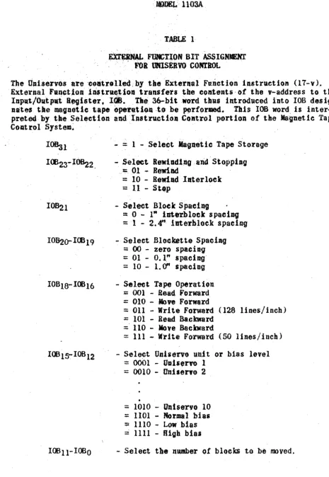
EXraNAL FDlCrION BIT AssIGHENT
:, roallNXSEaVOCONT10L .
The UniseJvo$ are 'c~u'tt(Jlle(tby tie 'External Ftulction iu.truetion (17-v). The
ExterDalFun~t1o"1n.tr_tioll
transfers
tbe contents-of the v-address to the InpRt/OutplttB.'oister,lea.,
The, 36-bit .WOrdthU8 introduced into lOB desig-nate, tbe magnetic tape operatltUl·to
be pe.rf9rmed. This lOB word. is inter-preted by the Selection and 'lnstrllctioll COlltrol portion of the Magnetie Tape COAt rol' System~ ,IOB:il
lOO23-1~2.
I0B2o-IOO19
lOB l!t' lOB 12
- ::: 1 - Sele«?t
Maglleiic
Tape Storage- SeleetlewlRdlllQ,alid Stoppiag
," :;01 ... Rewind
=
10 - Retdld IJtterlock ::: II - Stop- Select Block Spacing
:: 0 - 1" iDterblock s paciDiJ -== '1 - 2.4"' im.erhloek spaein-g
- Select Blockette SpstiAg
~ 00 - zero spaCing :;;: 01 - 0.1" spacing'
=: 10 - 1. (ff spacing - Seleet Tape O~rat1olt
;;;; 001 - Read Forward
=
010 - love Forward::; 011 - Write Forward (128 lines/inch)
%! 101 - Read Backward
~. 110 - love Backward
=
III - Write Forward (50 lines/inch) - SelectUniservo unit
or bias level:::: 0001 - Uui.,rvo 1 :::: 0010 - Oniseh'O 2
•
=: 1010 - IJrd$ervo 10
=
1101 - Normal bIas :;z 1110 - Low bias=
1111 - Bl~h biasTape ~ Length
Eqaipmeat (feet)
Unityper II
200
tJniprinter II 1500
Uni vac I Internal 1500
Card-to-Tape II 1500
Tape-to~ard I 1-500
High Speed Print.er 1500
1500
Teletape .. to*
Unit ape 200
Unit ape-to.
Teletape 1500
Uni tape Tr.ns~
mission 1500
'Unlv8cScientific-internal 1500
·Under Development
,- TABLE 2
DNITAPE STAftlAlWS
Density (Cha~8cter./
lachl, "
50
50
128
128
'128
128 .
50
128
128
128 '
128 Inter- \ Bloekette ~p,ce--:ipcbes 2.4
o
o
1.2 - 2 .. 2
.1 1.0 2~4 1,,0 1.0 1.0
o
Inter-BlookS
pet! ... i_gbes
VARIABLE BLOCK LENGTH
ON THE
1103A UNISERVO TAPE SYSTFM
1 DeClllBber1955
VARIABLE· BLOCK LEM7TB . ON
lRE
1103A llNlSERVO TAPE SYSTEM
As an additional feature •. extra.;CGtttrol citc"ltry Willbffprovidedon .81 optional basi. to allow a variaBle
l).Iock
lengthto'rat .
on
the .11~UJltser'(J tape system. The staDdard· lilted blo.ek.· lengtll for-lilt.de
ot~: o~ttitl(all 1s 80t· altered in any IQanner by tbe. addition of YViabl&blOekequllireat' •.Program selectiollof tile yar1ableblookJlIode
18 aceo:mpltshed
by. setti" . bits 10019 awtI(E20 both. equal to (ute, in. the. word. i~.ued· by th~ E~ernal .. ' .. ..FUllctions Inst.ructicD. The eo.Dtrolol the ,.arl0118 ttpe function,,:l:$ Provided.,:. by the saJne~6ntrol bits tis far fixed block 16.'11 format .!th··~litee· exc&p'lolt'J
.1. The variable block mode automatically seleets' the one if1cb··lnt:.rblock~· spacing' ..
2. Writing on tape in the variable block mode caD be done at a pulse density of 128 pulses per incb only.
3. There is DO provision forspaee bet.ween blockettes.
~EADlMi VARIABLE BLoor
Variable block length readillg 1s initiated','- ~fteblock at a ti"'~ by an External Fun~tion (11-v) iastructioft with the following bits seleeted:
10819 ;:. 1. 10620 = I (Variable Block); all other "selects" being tile s~ .. e as those for fixed block length readll1g.. In the same manner as in fixed block
re~diftg an Externa 1 Read instruction must be programmed to tran.s!!J!t each com-puter word ftoID lOB into storage.
, The tape unit will automatically stop at tile end of the bloc-k~ This con-t rol function is achieved by sensil19 t.he absence of sprocket pllls;ets. '1nttle . sp!lce betwe.en blooks. Speoifically t the stop cont.rol' iS8ctiYtltedwhen the sprocket pulses have been absent fcr! a per!od of time equal to tl&atof 12 s prooket pulses. A code will be placed in lOA to lndic8tt} the end of block condition. Th!s code consists of a one in IOAl.
l11enwrit,ing on tbe tape. an erase bead. eraseS the tape a length of 5 inches ahead oftbe write' head. Beoause of this, at th~ end ()f tile last .. variable .~lQCtt
there ldll"be a 5 inch end of ysriablerecord gap_ An attempt to. read"
j;
·~!:t;~~e ~=::1!:ta:::!ti:~J=~;orY~~~'i::J!~~'
's,l.t,S"of".'ott.·i1i:·_O~'·' "- ." . ' .. '~ " . ' · c " _ . , . . .'....:.:.>. ", ....
Xt:
i.a,pOs .. 1~le.'.to·: p~.~ aQ!xternal'uJlet1(fn·lnst ... ~tloJl·.t:O i;.top·tape·:re.dlngd.rlng·.t~e r~.tltO '.~~'.' a ~~riable blo.k. "IiLthl~.':/c~l.e t .:tJte·trapeunit
.' "is braked loa.top .. :·The • •
ct
di~tance' tke.·"pe . .,111o'&a.tciiIJD(Jt)Ht·pre-edsel, deterttilted and
if
tile read ope'~ation is again l'flJ.tmed .fllforasa~10., will· be. lost·"
'JlIT~ VAl.lAU .SLOC¥
Varl-il>le..
·blbok~ltiJli.;l:l:lrdt'lat~»r'
aa
Extena!
FuD.tl:oir:lt~'.i ltt$:t.tut~
tl~ •• '.l;'''::~he tol14nUIll' bltJ'4'lHt$4.t ... " ....
,-'. I.
OBl97.1.>I~;.·2-
.. ·· ..
tJ:.1 .... :; .. '. all.ot.b ..
ft
... : .. " •.
,elftet. '$". be ... 1.0' .. '. t.ke .. ' ..$.rute.,~
.' .. ' .as ....
·.~o
..
r ...~
....l~
... :
... :
'.iJlfR.'" ·.:.:k· •... ·, i.' :t.;,::1.:" ..~
· As witli' ,!1xttd:~1.k ..,1 tIn.S.;. IAn Exter.al.·l'itet,ut.nctiQ,tJ h·lt. :b.··PX0tra ... tt,,·
· for .eat. _td.i.t:'-.D$.lttedJtr.m·$'to~afe·to
JJJe
'tep$ :llnJ'~·, ... " ',: '. '.' ~. .'. Atthe:_'.pl'
tJl'e
i.rJt-.-n9:
ope'l;tltlon.
a->:gtup:E~.lsa.l· F,'~ .• llol1 ,~ae~.t;io'r( · lI\t't,.~be 1~.tit<11 .... ~1ate~t t:~l~oW1.ittJ (within 25~cr~see~n.)·thetetiatllaf · Exterllal ~::' . ' . . Wl'ite-lnitl'\{~tlo ." . . .. " . •• ·. "; . . . ., . Th,ere.
is;;·~.f{ ~!!~e'h~ad
.•pace4appr:~imate11 llt.:l.~~espr"e.dl09:th"··~.dl
:
r~~Rl~ ~~adJc,·~:~I' .. t1t.·::_f:tV6,t.~h,~Pfl'.· .followt,nt'.t.lle .. la~~~wrltt.eJt blopk will . · btt hl.n~~·r.is .• paceJj·us .• d·;to seQse tile cmtIet v'l'i •• le."'r~cq~:cQlldlt:lq;IJ:',wheareadi·nv.,-' ' . , '
'mE UNIVAC SCIENTIFIC
ntPtJr/OU'I'PtJr INTERLOCK SYSTEM
ON lOA AND rOB
1 December 1955
DIVISleN OF SPERRY RAND CORPOR/.riON
DEscrtiPTI
<14
(J1 THEINPUT..ooTPfJr IN'l'ERLOCK SISTEM
cr; lOA AHD tOB
A functional part of eaCh of the Input.-olJ,tp.t registets IOA and lOB is a flip-flop lnterlock~
1. . Transmissions lx-om lOB or lOA to' external equipment.
When 811 External Wri.te iUitruetlon causes
toa
or lOA toDe
lo.dedfram storage, the flIP-flop Interlock tsset to the "on.e" state. The removal Qftbis word {rOOt lOA· or lOBby
a piece of extenal ~utpmeDt aets tbe lJtterlockbaekto the "zero" state. 1ft theev_t that a $ecOJid External Wrl te lD.s·tnetioll Is
executed before theextenal equJ.pmeDt ttla obtained the previ01l$ word trOm lOA
or IOB. the execlltion of the Extel'llal Write .i •• traction is held Up UJltll the inlel"lock is cleared (at the time the'previous word is transmitted to the ex .. ternal equipment).
Howevor. if the external eq1&ipmeat call. for theaext word from lOA or
roo
before lOA or rOB has been loaded by _Extent.a! Wrl te illstrllcti oa. an 10 FAtJLT
will oeeu,r. This is a class B eompateFfault. . .
2. Transmission to lOB or tOA from extanal equIpment.
When a transmission from. pieee of external eqllipmeat to lOA or lOB
occur$,~ the flip-flop interlock is
set
to the "one" s·tate; the execution of an ExteI11al Read iJ1struetiou causes the fl1p ... flop to be set back to the "zero't: state. If an Extel1lal Read iutraction attempts to read from IOA or lOB before the llip ... flop has been set to the ~one" state by the external equipmellt tbe execution of this iastrl1ctioll is held up.. When th$ next word is trqsmi tted from the extemal equipment, the flip-flopia set to the "oa." state and the External Read instruction is· completed.. If the external equipment attempts t'otransmit a word to
lOB
or lOAwbelt the flip ... flop is in. the "ona" state (the last word is still in lOA or lOB) t ail 10 FAtLT will occur. This ·is a clus B taul t.THE UNIVAC SCIENTIFIC
STORAGE OF LOADING ROUl'INES
10 December 1955
DIVISION OF SPERRY RAND CORPORATION
MODEL 1l03A
THE UNIVAC SCIENTIFIC
STORAGE OF LOADING ROUTINES
General
Programs may be loaded into the Univac Scientific, Model IIOJA by means of the Uniservo tape units, the punched card equipment or the rhoto-electric readero - Since each of these input devices is controlled by the
External Function instruction, a short stored program is required to read information into the computer. A progr""alIl for loading from magnetic tape, punched cards or paper tape can be more or less parmanently stored on the magnetic drum. However, the loading routine is subject to obliteration by programming or operating errors and tests of the drwt system.
The need for manually reentering a loading routine may be avoided by storing a copy of the routine in the relatively invulnerable "dead spaceR
on the magnetic drum. Should-the loading routine in the normal drum storage be damaged, it may be restored by a transfer from the dead space.
The Magnetic Drum Dead Space
In addition to the tracks on the drum which are used for storage of information there is a timing track and a mark track.. Tne timing track notches are used to identify discrete angular positions of the drum. The . mark track contains a single notch which serves as a reference point during
- each drum revolution from which angular positions are counted. The first 4096 timing notches following this mark indic~te the lines on the drum which are normally addressable.. Those positions between angular position 4C95 and the w~rk at angular pcsition 0 are called the "dead space". Every drum has a dead space of at least 128 lin~so
. The angular pesi tion of the dI"Ull1 corresponding to a progrmn address is identified by a coincidence between the contents of the Angular Index Counter and the interlaced address. Normally there is no communica tion with the dead space since when the Angular Index Counter reaches 4C95 the next timing pulse produces an "end carry" which disables the coincidence detector until the mark is reached~ The Angular Index Counter continues counting~ At the mark the Angular Index Counter is reset to zero and the coincidence
detector enabled.
By means of an ABNORMAL/NORMAL DRUM switch on the Supervisory Control Panel the lockout on the coincidence detector may be reversed. When. this 614i tch is sat to ABNORMAL, the lockout is established by the lr.ark pulseo The
ADDRESSING THE DEAD SPACE
The addresses available in the dead space duplicate the normal drum addresses but because of interlace are not com~letaly consecutive. For
example, assuming 128 lines are used in the dead space, the addresses avail-able with an B interlace are:
40000 - 40017
41000 - 41C17 42000 - 42017
47000 - 47017
with comparable sets for groups 5, 6, and 7. When the ABNORMAL DRL~ is sel-ected references to these addresses will result in comm~cation with the dead spacee References to other addresses 'Jill cause the computer to "hang
up". When the NORl'.tAL DRUM is selected thare is no con:rrrunication with the dead space.
UNIVAC PERIPHERAL EQUIPMENT
FOR USE W'ITH THE
UNIVAC SCIEi'-tlJ'IFIC, MODEL 1103A
1 December 1955
DIVISION OF SPERRY RAND CORPORATION
$HGJHEERIHG
~S[ARCH
,fsSOCIATES DIVISiONtlNITAPE
",1f.tPBa'
~n,e 'Uultape
1,$'
'u:sea't~~;,~'Ord data.insttll,ctio~. <or,cQltf:t.At:.~';tQ:rtheUni vat' :Scientlf lc'SY~~lelt. ' ,', ' ; , '.-"': ',
':BAS,lCSffiflnCA!~QPIS~. -of
~:rae:
taPt' ,is::'~t~ilf'e.:
,i/2-":tdde,'
sndappr~';till18te11: ()~:oor' tJll~k~(
,"
It',i~""iuP.p~'i"
, ,i~ 1500i.,500:~'t,'~Q09"tr'lOO9 left~hs' 8S ,:ribbOn WOUd;·('la:reel,s' ,~" in, dia_t.~~
[Tile shor~e:t.·.~eels'. <200~,alld; lOQ-lIare. 'pr-imarilY .!6r :,ti$~; wlthtlle>.'Unitypers~,~,;' ;,t~fll, 6#: Il1df;~meter'ts 'used Wff)l Unftyper II." ' ";'" " , ; ' , '
" ,
':,The plat84llu;!~ee',of·'·:'th·eta:Pe will'wftutand'at le.~s,~·',TOO, ~~s.s·,oyeta _g":'
"-Betie readIng-recording ,head: wi'tbo-ut'destrtlyfng , or ¢:auslb,a.ppr(!~flt4'ble ,deter~', , ;lorat~on;'ot'the'liiagnet!e Pl'.p~ttl#$. ,tTl'lde-r :-no.rl1laI ,~o.dltl()#!J,,'sennl'th1es " .. '
',~ .fl;",pa$,s,e~~y:be: 'exp~ted: ~'"
','
,g$t0lID1~
,
',.lnlo;t"tDation:1s
/~()rd~ 'ont~_e.t~~:p1tlie.': ti.lt1$>~~'~ ,Cal'<l~t~Tape COB"&rte~ ~'
" 'a. ,by" t{nlva~, Sclentitl~. The : d$tl~tl at wkj~h.f..~,eharae~~l"s 'are _ree()fd~ ",4,pettd.
upon, the COPJponent ,or i,n .t~::case of r'Un~t~);Stl~t'i..f,ic; 'upon t~< in-'stt:rlctioJts 'u.t"ld. :,Charaeter,iDar be recorded :at 8
densIty
oflOO,to
128 pulseS. per lineat ·ln4hQt 50' pu!s·es. per liD'eariuea.
.JI+r-"QPACITY :''','' .
,The tape eapacity of a ~500II,r.el·de~nds np<)~:tle .de.aSiltaQf the
reccrfl1ne' •.
. z .. ,~~.
; Biah
,Pl.\ls e':oen$',~X 1.440. OOOcbara6ter$ "240 t 000 \fOras
. 2 , OOObli)c}t.s :
"
Low hAS! D;f1$'l tJ
"
288.000 c:haraotet8
120"'009
",rds,-, ~" OOQ b'loc kB
The equivalent capacity o'f the
,tape,
1$ approximately 16,000 to 25,000' p04betj,' "'card$. ' , . "
·.!APE',
EMSJtBE .
,'The tnetallie1
tape maybe era;,Qo'."$ ~lten as de.ired and new In!otFJatiotl re.:...,
'~or4$1
on
1tot
'
,
~J':-~;Dt.:':':~Jti!~l~~$t;1t:.!;Ytt';:llt!;2!t~~~~·'·'·
{t loa~f.Ut8: .. tilt. e" .-:l1l$'~tU.etl-~n PH'l{'\i;~D-',~~_ SQ~t)tl,::te~~l1.::'taJn._t -:ii)C--t~\..t _
,;-_~e'l1$.qe:,()1 the tape., ' Wh •• ~tlt.:l"e~ri.l~:.on.~he tfJ~-.'f,\:o~·~r-·e,ytd'.-':t_,li:":
'-ria,
,~J-~$erted'·by'the'
'ope.ratG-r.«_:I't-s~:~ttlest.ll1 ~,..t~.~:: ::tke' tape ,:t~;'be'_:~ :,': " ' 'A rub)jtl'~:>plugp,..evellt. ,tbetllpet~tQ~lUlwi~lng.:. - -' ,',' - - , ' ," '::.. . .. . ..' " . . . : . . ~ , . ' " ... ...,:. . . . . ~ . ,,;..", .
:T.apt~·.:.al'~:'el)at~~~llr,:-_te:&:~~'.te',;.~'~t,-.{p~9Per':'_-recordi'n9;S'tir!ates-~-.::,: -~~~~::}~t~_:·~::,,_,,'."
---;>::~h~':"~f9te:' ~lul.~~~:t.tOll:;'1~~f~l.c,{~l.as _ artd'Q,~dlt:,to~~ l: _
tea"
~'l,,1t~lL'.-al~,' _,to,-t":~~tJ\~hed.areaS-'-Fo.:r,~mp.1e.: 1:()25;~': al'~$.llPpl$,~'
f
or,
8 1,:500-9 ,t.-pe.<"',fJie' ,. TRE UNISERVO
PURPOSE
The Uniservo transports· tape over a standard magnetiC head (for reading and recording) under the control of Univac Scientific Computer System.'
BASIC SPECIFICATIONS
The Uniservo is housed in a cabinet, the upper section of which contains the reel mounts and is c.overcd by a .s lidlng plastic door. The door eatu;lot be Qpeaed without turning off the main operating s\dtch on the front panel of the Uniservo. The entire front panel is easi ly removed. g1 ving access to the loops.
OPERATION
. Height Width Depth
Working Spaee Weight
INPUT FUNCTION
61'· 30" 21-3/4"
6115" by 5i9tt-3/4"
463 lbs.
A Uniservo
may
be used to read the eoded, magnetic dots on the tapemovillg forward or backward and transfer the data in the form of electronic pulses to Univac Scientific.O(JrPUT FlOCTION
A Uniservo
may
be used to record the results of Univac Scientifie proceJ-· sing lnt-he form of coded, magnetic dots on a metallic tape moving forward.The reel mOllnts hold tbe standard 6 inch or 8 inc.h reel of tape. TAPE HANDLING SYSTEM .
There are 3 independent. servo syst,ms -·the center drive and the reel motor servos. The cea.t'er drive iscoDtrolledby UQivaq ·Scientiftc.. The
MYLARTAPECONfROL
Ilylartape Is used between the reading and writing head of the Uniservo and tbe magnetic tape. The Mylartape moy~S at approximately 10 inches ·per hour. It prevents the.reading head from ·wearing and drastically reduces magnetIc
.tape wear. '
STANDARD MAGNETIC HEAD
The stan.dard magnetic· head reads from or rec-ords in 8 channels. Seven of the channels are used for the six data bits and a parity bit of the Univac Scientific System and the 8th channel is a sprocket channel.
TAPE SPEE:D
100" per second.
SAFETY SWITCHES
The Uniservo is fully equipped with safety switc~es which stop all motors and apply brakes if either oftJie two loops exeeeds the prescribed 11011 ts.
CONTROL
The control of a Uniservo is maintained by Univac Scientific and exercised during a program by the following types of instru~tions~
Read Forward Read Backward
Record at higb pulse density. Record at low·pulse density Rewind withQut interlock Rewind with interlock Move Forward
Move Baekward
CONNECTION TO UNIVAC SCIENTIFIC
As many
as10
Uniservosmay
be connected to Univac Scientific at anyone time. Oniservos may be electrically' interchanged without affecting the program.POWER . MQUlREI!EN!S
UNITYPER II
PURPOSE
Unityper II records on metallic magnetic tape the coded 'symbols of the alpha-betic and numeric charaeters of a standard typewriter keyboard as well as
cer-tain symbols used by the Univac System and prints simultaneously a ty.ped copy of the reeording~
PHYSICAL CHARACTERISTICS
Unf:typer II consists of three uni t8. assembled togetber~ a DIOdified Remington
Electric Typewrlter, a Tape Panel, and a Power Supply.
Height Width
Depth
Weight
14-1/4"
lr
241t 100 Ibs.
Tile Unityper II is. a self-contained, portable unit which·is intended for opera-tion OD a regular drop~center typewriter desk of suitable center depth. The
working space required for a Unityper II is the salle as that allowed for a typewriter. A tape panel is placed on top of a special case-work extending to
the rear of the basic typewri ter u-ni t. The power supply is located under tbe tape panel and contains all the necessary circuitry to provide voltages for recording and erasing.
OPERATING CHARACTERISTICS
A. The
Remington ElectricTypewriter
The Remington Electric Typewriter keyboard includes all the standard alphabetic and numeric characters and punctuation marks. The letter spaoing is 12 characters per inch. Certain modifications to the stan~
dard keyboard and type font have been made which are as follows~
1. All alphabetic characters are represented by capital (upper case) letters.
2. The numerals. appear on the top row of keys in their usua 1 lower case positiQn and include a key for the figure 1 located to the
left of the key for figure 2 •.
3. A standard ten key numeric bank (3 keys wide and 4 keys high) is
4. O,peration of the space bar places a caret (1\) on the copy.
B. The Tape Panel
The Tape Panel houses the following:
1. the take-lip reel with a fixed length of leader attached to it. 2. the supply reel mount on which the operator places the tape before·
recording. Unityper II uses a reel. six (6) inches in diameter. It holds 200 feet of tape on which more than 55.000 characters can be recorded.
3~ a magnetic head for recording.
4. an eras ing head' which obI! terates prevIous ly rE;tcorded information· before the new recording takes place.
5. other electrical and mechanical devices required to control the direction and· timIng of the tape motion.
6. the operating lever which controls the cycle of LOAD LEADER, TYPE, REWIND and UNLOAD operationso
c.
The Power SupplyUnityper II operates from 115 volt, 60 cyclet AC single phase power .lines.
Its power consumption is 75 watts. Line voltage variations of as much as
=
l~fo are permissible. D. Recording Operation1. Typing Ra te
A mechanical bail interlock system is incorp.orated in the typewriter to prevent the striking of two keys at once. This device limits the typing rate to a maximum of twelve (12),characters per second.
2. Pulse· Density
The coded symbols are recorded by Unityper II on the metallic tape at a density of 50 characters per linear inch.
3. Line Length
A ten-inch carriage travel is permitted, allowing 120 digits to be placed on a line. A line guide with 120 numbered divisions indi-cates ~o the typist the digit position at any point in the line. Each line of 120 digits is referred to as a "blockette" and OCCU-· pies 2.4 inches on the tape. When the carriage reacheS the 1215t digit position, the operator may then operate the TRIP Key which will print an underscore and return the carriage. As the carriage
4. Block Length
A block of information consists of six (6) bloc~ettes (including the space between blockettes) or 720 digits and occupies 28.8 inches on the tape. Space between blocks is the 2.4 inches be-tween the 6th blockette of one block and the 1st blockette of the next.
EO' Control Keys
1. Operating Lever
A mechanical operating lever is mounted on the left side of the Tape Panel and controls the cycle of LOAD LEADER. TYPE,REWIND and UNLOAD. The lever is pulled by the operator to perform two types of operation: to load the leader or to rewind the tape. The tape moves during these operations without motion of the carriage. The lever is inoperativey when the access door to the Tape Panel i~ open, when the carriage is not in the first
charac-ter positIon, or when a Load or Rewind operation is in progress.
LOAD WDER
As the operating lever indexes the control Cam into the LOAD
LEADER positions, Unityper II automatically loads fifteen feet' of tape as a leader on the takeup re~l.
REWIND
In the first-digit position or any line or blockettet an opera-tor may choose to type or to REWIND. To REWIND the operator pulls the operating" lever.
2. Fi 11 Selector Swi tch
The operator may selectr with the use of the Fill Selector Switch, either zeros or space symbols to fill in the rest of the field, blockette or block (See Tabulator or FILL Key).
3. Backspace Key
The backspace key moves the carriage and tape backwards one digit-s pace at a timet' eras ing the information on the tape at the same
time. 4. Era"sa Key"
5. Fill Key
Operation of the fill key causes the carriage to move to the next tabular stop.· As it does so, the tape is also DIOved a correspond-ing distance and fill-in characters are recorded on the. tape. The tabular stops are set manually and function in the same manner as those on a standard typewriter.
6. Trip Key
When the TRIP Key is depressed at the 121st digit position. it will:
a. print an underscore
h. return the carriage
c. move the tape forward 2.4 inches to allow for spa·ee between blockettes and blocks.
d. advance the paper feed.
No information is recorped on the tape during the TRIP operation.
CHECKING FEATURES
1. The access door to the Tape Panel is locked while the operator loads the leader t types and rewinds the tape.
2. The keyboard is locked during the LOAD LEADER. REWIND and UNLOAD operations.
3. The operator cannot.move the carriage is either direction except from the keyboard. in which case there is either some symbol prin-ted on the pa.per, or a blank area of paper which indicates a
f111-in operation.
-4. The TRIP Key may be depressed at any position other than the 1218t digit position, but_will merely print an underscore without movlng-either carriage or tape and without recording any character on the tape.
UNIPRIN'RR
PURPOSE
The UNIPRINl'ER converts the coded, magnetic dots recorded on
,.
8 metallic tapeto a typewritten copy.
BASIC SPECIFlCATIQNS
The UNlPRINI'ER con.ists of two assellb11es eODll8Cted together by a cable: the'-' Tape Reader and
the
Printing Unit.Height Width Depth
Tape Reader
47-1/2" 29" 21-1/2"
Printing UnIt'
44-1/2" 29" 21-1(2" Working Spaee
Weight
6115" by 59-9-1/2"
410 Ibs.
6115" by 5'9-1/2"
244 Ibs.
-OPERATION
TAPE READE R
The Tape Reader contains the motors and standard magnetic reading head over . which the tape passes. It also contains itS' own power supply and other
e leet ronic components.
P RI Hl'l NG UNIT
The Printing Onit is an 1ntegral part of the UNIPIUNTER. It prints the letters, numbers and symbols that are read froll a tape _u.!!ted on the Tape Reader and performs the typewri ter actions suc'h as Ca rriage ReturD, Tabt11a~
tor key, ete., in accordance with p.\llse combinations on the tape (See Pri'nting Unit)..
SPEED
About 10 characters per second.
co
NT ROt SWITCHESUNlPRINTER
THE UNIVAC
THE UNIVAC
HIGH SPEED PRINTER
PURPOSE
The High