A GSA Based Generalised Formulation of
SHE-PWM Problem of Multilevel Inverter for
Both Equal and Unequal Source Voltages
Sayanti Ray
1, Pradip Kumar Saha
2, Goutam Kumar Panda
3P.G. Student [Power Electronics & Drives], Dept of EE, Jalpaiguri Govt. Engineering College, Jalpaiguri,
West Bengal, India1
Professor, Dept. of EE , Jalpaiguri Govt. Engineering College, Jalpaiguri, West Bengal, India 2 HOD, Dept. of EE , Jalpaiguri Govt. Engineering College, Jalpaiguri, West Bengal, India 3
ABSTRACT:A generalised formulation of SHE-PWM technique applicable for high power voltage source cascaded
multilevel inverter used in constant frequency utility applications has been discussed in this paper. The SHE-PWM scheme features a broad solution space. This paper aims at to eliminate low order dominant harmonics and at the same time maintaining fundamental also. Since SHE equations are non-linear transcendental in nature , to solve these equations a new artificial intelligence technique called Gravitational Search Algorithm has been implemented to find out switching angles with faster and guaranteed convergence. To illustrate the effectiveness of the proposed method, a phase five level voltage source inverter has been considered with six no. of switching per quarter cycle. Since for a 3-phase balanced system all the triplen harmonics are absent in the line, thus in this case with six no of switching per quarter cycle, five dominant non-triplen harmonics (5th to 17th) was possible to eliminate using SHE-PWM technique for both equal and unequal source voltages for a wide range of modulation index and voltage ratio. Then the output voltage THD obtained using this approach is compared with another approach for minimum system voltage THD.
KEYWORDS: Gravitational Search Algorithm, five level Cascaded Multilevel Inverter, Selective Harmonic
Elimination-Pulse Width Modulation, Harmonics
I.INTRODUCTION
Multilevel Inverters have drown tremendous interest in recent years for high voltage and high power application. The term multilevel inverter starts with the introduction of three level inverter. To change a dc input voltage to a symmetric ac voltage of desired magnitude and frequency is the main function of inverter. To avoid the limitations of two level inverters as high switching losses and low efficiency, multilevel inverters are widely used for their better performance as lower common node voltage, lower dv/dt ratio, lower harmonics in output voltage/current and lower switching frequency with reduced switching loss. The unique structure of multilevel voltage source inverter allows them to attain high voltage with low harmonics .By increasing the no of level in a given topology, the output voltage waveform approaches close to the desired sinusoidal waveform with low harmonic distortion. To get improved quality output voltage from inverter, undesired harmonics is required to be eliminated. There are various methods to eliminate harmonics such as Sinusoidal Pulse Width Modulation, Space Vector Modulation, Selective Harmonic Elimination, Space Vector Pulse Width Modulation, Selective Harmonic Elimination-Pulse width Modulation. Among various techniques of harmonic elimination, SHE-PWM offers a better control over low-order harmonics and better dc source utilization. To obtain switching angles from those non-linear transcendental equations which have multiple set of solutions is the main challenge of these modulation techniques. Again to get optimal solution from non linear equations, there are various techniques with their individual advantages and disadvantages. Proposed GSA technique provides optimal solution with fast convergence.
that exhibit multiple set of solutions. The main challenge associated with SHE-PWM technique is to obtain optimal solution from those non linear transcendental equations. There are several algorithms to deal with the SHE-PWM problem which was either to rely on initial value for exact solution or to introduce transformation steps to ensure fast convergence and also to find out multiple set of solutions. There lots of efforts have been made to find out effective initial values to guarantee rapid convergence of Newton Raphson iterative method [4],[5],[12]. SHE-PWM technique is highly suitable for the control of single- phase and three-phase full-bridge three-level inverters for any switching angles[12]. The algorithms include introducing transformation steps to ensure convergence and to find out multiple set of solution through Homotopy based computation [6],use of Resultant theory [7],use of Walsh function[8],and optimisation technique such as genetic algorithm[9],through a colony of ants [10], and optimisation search[11].Resultant Theory converts the transcendental equations into polynomial equations and provides a complete solution [7].Instead of solving nonlinear transcendental equation, Walsh function solves linear equations which optimises the switching angles[8]. Genetic Algorithm has been used to find out the switching angles from nonlinear equation using. This solves the same problem with a simpler formulation and with any number of levels without extensive derivation of analytical expressions [9]. A new artificial intelligence technique is used through a colony of ants to solve non linear transcendental equation for better convergence [10]. There is a new technique has been introduced recently to eliminate higher order harmonic by simply generating the opposite of the harmonic to cancel them. But it has a disadvantage of using high switching frequency[13],[14].Optimal pulse-width modulation (OPWM) is often used in medium-/high-power inverters, to reduce the switching frequency. For two-level and multilevel inverters with unbalanced dc sources, equal area criteria-based four-equation method has been developed to realize OPWM [15]. A novel formulation of SHE PWM equation for multilevel inverter was proposed with quarter wave symmetry which was applicable to any level and any topology which increased the flexibility of the proposed model [16].A staircase modulation control has been implemented to achieve minimum output waveform distortion in single phase multilevel inverter when ratios between their dc sources are non-integer values with considering device voltage drops [17]. A generalised formulation is also developed for half wave symmetry selective harmonic elimination for voltage source inverter with illustrated basic concept of half wave symmetry, quarter wave symmetry and asymmetry wave forms. This method also gives the flexibility to deal with different phase shifting as phase shifting does not change the frequency spectrum of a waveform. The rule of equal area criteria and super position of CG of the PWM section with reference sine wave can also be adopted here [18]. A generalised formulation of SHE-PWM technique for multilevel inverter considering both equal and non equal DC source voltage has been formulated. Here the necessity of Hybrid Genetic Algorithm Implementation is also been mentioned distinctly [19]. Recently a new artificial intelligence technique named Gravitational Search Algorithm has been implemented to solve SHE-PWM problem with fast convergence to find out optimal solution [20].
In this dissertation, a generalized problem has been formulated considering variable DC voltages (for both equal and unequal source voltage) for 3 phase 5 level Cascaded Multilevel Inverter with quarter wave symmetry using SHE-PWM (Selective Harmonic Elimination-Pulse Width Modulation) technique to eliminate lower order dominant non triplen harmonics like fifth, seventh, eleventh, thirteenth and seventeenth with maintaining the desired fundamental component. The transcendental nonlinear SHE-PWM equations are solved using Gravitational Search Algorithm, a very recent artificial intelligence technique with fast convergence to find out the optimal solution. Further, to have better overall system THD, two methods has been employed here. Firstly, with calculated switching angles, THD upto 31st harmonics has been calculated. Secondly, considering upto 31st harmonics within the objective function, switching angles have been calculated and THD have been compared in between two methods. Finally the second method was found to be more efficient for overall system THD.
II.MULTILEVEL INVERTER AND ITS MODULATION TECHNIQUES
The term multilevel began with the three level converters. However, the elementary concept of a multilevel converter to achieve higher power is to use a series of power semiconductor switches with several lower voltage dc sources to perform the power conversion by synthesizing a staircase voltage waveform. With the increase in number of voltage levels, harmonic contents of the output voltage waveform decreases significantly and output waveform becomes more smooth minimising harmonic distortion. Capacitors, batteries, and renewable energy voltage sources can be used as the multiple dc voltage sources. A multilevel converter has several advantages over a conventional two-level converter that uses high switching frequency pulse width modulation (PWM).
1. With respect to diode clamped or flying capacitor types, cascaded multilevel inverter requires least number of components to reach the same number of level voltage.
2. There are no extra clamping diodes or voltage balancing capacitors.
3. Soft switching techniques can be used to reduce switching losses and dv/dt is decreased. 4. In case of any breakdown, each module can be replaced; this reduces the down time and
increases the continuity of power supply.
5. With the increase in output levels, harmonic distortion is reduced.
Fig 1. Topology for 5 level cascaded multilevel inverter Fig2. 5 level phase output voltage
Each H-bridge shown in Fig. 1 could produce three different levels:+Vdc,0,-Vdc by connecting the DC supply to AC
output side by different combinations of the four switches SX1, SX2, SX3, SX4 where X represents the H-bridge number.
An n-level topology requires 2*(n-1) switches and (n-1)/2 isolated power supplies. The 5-level inverter shown above requires 8 switches and two DC sources per phase. The resulting output ac voltage swings from-2Vdc to +2Vdc with
five-level i.e -Vdc,-2Vdc, 0, +Vdc, +2Vdc are the possible voltage levels. To obtain +Vdc , S13, S14, S23, D21 switches are
turned on. The output voltage would be made zero while switching on either the switch pairs SX1 and SX3 or SX2 and SX4
where X represents the H-bridge number. To obtain -Vdc , S11, S12, S21, D23 switches are turned on. Again to obtain
+2Vdc, S13, S14, S23, S24 switches are turned on and for -2Vdc , S11, S12, S21, S22 switches are turned on. To obtain three
phase connection, the outputs of three single phase inverters could be connected in star or delta shape. Fig 2 shows the per phase SHE-PWM output voltage wave form of a 5 level cascaded multilevel inverter with 6 switching angles considering quarter wave symmetry.
III. A GENERALISED SHE-PWM PROBLEM FORMULATION
Fig3. Generalized multilevel PWM waveform
Fourier series expansion of the generalized multilevel PWM output waveform of the single-phase multilevel converter shown in Fig.3 can be expressed as follows
𝑓 𝛼 = 𝑎𝑛cos nα+ 𝑏𝑛sin nα (1)
∞
𝑛=1
Due to the PWM waveform characteristics of odd function symmetry and quarter-wave symmetry, the output voltage can be reduced to
𝑓 α = 𝑏𝑛sin nα (2)
∞
𝑛=1
Where bn is the Fourier coefficient.
A generalized expression of for any number of switching angles and any number of voltage levels and with equal and non equal dc source voltage is given by
𝑏𝑛 = 4𝑉𝑑𝑐
𝑛𝜋 𝑉1 (−1) 𝑖+1 𝑃1
𝑖=1
cos 𝑛𝛼𝑖± 𝑉2 (−1)𝑖 𝑃2
𝑖=𝑃1+1
cos 𝑛𝛼𝑖± . . ± 𝑉𝑀 (−1)𝑖 cos 𝑛𝛼𝑖 𝑃𝑀
𝑖=𝑃𝑚 −1+1
(3)
Where
V1 ,V2,...VM are several dc source voltages
n=1, 3,5...2N-1 for single phase system
n =1, 5, 7...3N-2 for three phase system(N is odd) =1, 5, 7...3N-1 for three phase system (N is even) M=No of dc source voltages
VMVdc is the value of Mth dc source
P1=N1 ; P2=N1+N2 ; PM= N1+N2+....+NM
N1, N2,...NM are the number of pulses per-quarter cycle at converters respectively
N= N1+N2+....+NM (total number of pulses per-quarter cycle)
αi is the ith switching angle
For a 3 phase cascaded multilevel inverter with 2 sources and 6 switching angles per quarter cycle, the above equation can be written as
4
𝑛𝜋 𝜌 cos 𝑛 𝛼1− cos 𝑛𝛼2+ cos 𝑛𝛼3 + (cos 𝑛 𝛼4− cos 𝑛𝛼5+ cos 𝑛𝛼6) = 𝑏𝑛
𝐸2
= 𝑚𝑖 (4)
Where mi is the Modulation Index
mi=
𝑏1 𝐸2
ρ=
b1 is normalized fundamental component
M is the no of DC source
Vdc is the input dc voltage source of each converter cell.
ρ is the voltage ratio
Case I: EQUAL SOURCE VOLTAGES
First Approach:In this section, it is assumed that the levels of the dc sources of the cascaded converter cells are equal
and constant, i.e. V1 =V2=... VM, p.u., hence ρ=1.
Therefore, one can rewrite the above equation (4) as follows:
4
𝑛𝜋 cos 𝑛 𝛼1− cos 𝑛𝛼2+ cos 𝑛𝛼3 + (cos 𝑛 𝛼4− cos 𝑛𝛼5+ cos 𝑛𝛼6) = 𝑚𝑖 (5)
For n=1,5,7 ..17, equation (15) will be successively as follows:
4
𝜋(cos 𝛼1 − cos 𝛼2+ cos 𝛼3+ cos 𝛼4− cos 𝛼5+ cos 𝛼6) = 𝑏1= 𝑚𝑖 (cos 5𝛼1 – cos5 𝛼2+ cos5 𝛼3+ cos5 𝛼4− cos 5𝛼5+ cos5 𝛼6) = 𝑏5= 0
(cos 7𝛼1 – cos7 𝛼2+ cos7 𝛼3+ cos7 𝛼4− cos 7𝛼5+ cos7 𝛼6) = 𝑏7= 0
... ...
(cos 17𝛼1 – cos17 𝛼2+ cos17 𝛼3+ cos17 𝛼4− cos 17𝛼5+ cos17 𝛼6) = 𝑏17= 0 (6)
An objective function describing a measure of effectiveness of eliminating selected order of harmonics while controlling the fundamental must be solved to obtain the optimal switching angles and that is defined as
F(α1, α2,... α6)={w*(b1-mi)2+b52+b72+ b112+ b132.+ b172 } (7)
b5,b7,b11,b13,b17 are the 5th ,7th ,11th ,13th ,17th harmonics accordingly.
The optimal switching angles are obtained by minimizing above objective function when it is subjected to the below written constraint.
0≤ α1≤ α2≤ α3≤... α6≤π/2; (8)
VTHD(%) has been calculated considering upto 17th harmonics and VTHD(31)(%) has been calculated considering upto
31st harmonics.
Second Approach: In this case, six switching angles have been calculated including 31st harmonics within the
objective function. The objective function is given by
F(α1, α2,... α6)={w*(b1 - mi)2+b52+b72+ b112+ b132+...+ b312 } (9)
With this obtained switching angles, VTHD(31)(%) has been calculated.
Case II: UN-EQUAL SOURCE VOLTAGES
First Approach: In this case we assume that the levels of the dc sources are non-equal (V1 ≠V2≠...≠ VM) . Voltage
ratio ρ has been varied from 1.1 to 2. For n=1,5,7 ..17, equation (4) will be successively as follows:
4
𝜋{𝜌(cos 𝛼1 − cos 𝛼2+ cos 𝛼3) + (cos 𝛼4− cos 𝛼5+ cos 𝛼6)} = 𝑏1= 𝑚𝑖 ρ(cos 5𝛼1 – cos5 𝛼2+ cos5 𝛼3)+ (cos5 𝛼4− cos 5𝛼5+ cos5 𝛼6) = 𝑏5= 0
ρ(cos 7𝛼1 – cos7 𝛼2+ cos7 𝛼3) + (cos7 𝛼4− cos 7𝛼5+ cos7 𝛼6) = 𝑏7= 0
... ...
𝜌(cos 17𝛼1 – cos17 𝛼2+ cos17 𝛼3) + (cos17 𝛼4− cos 17𝛼5+ cos17 𝛼6) = 𝑏17= 0 (10)
Again using objective function as given by equation no (7) with the constraint as given by equation (8),switching angles are being calculated .Similarly VTHD(%) has been calculated considering upto 17th harmonics and VTHD(31)(%)
has been calculated considering upto 31st harmonics.
Second Approach: In this case, six switching angles have been calculated including 31st harmonics within the
IV.GSA AND ITS IMPLEMENTATION IN PROPOSED PROBLEM
In solving optimization problems with a high-dimensional search space, the classical optimization algorithms do not provide a suitable solution because the search space increases exponentially with the problem size. Over the last decades, there has been a growing interest in algorithms inspired by the behaviours of natural phenomena
In this paper, a new optimization algorithm based on the law of gravity, namely Gravitational Search Algorithm (GSA) is proposed. This algorithm is based on the Newtonian gravity. ‖. The obtained results confirm the high performance of the proposed method in solving various nonlinear functions.
In this section, we introduce our optimization algorithm based on the law of gravity. In the proposed algorithm, agents are considered as objects and their performance is measured by their masses. All these objects attract each other by the gravity force, and this force causes a global movement of all objects towards the objects with heavier masses. Hence, masses cooperate using a direct form of communication, through gravitational force. The heavy masses – which correspond to good solutions – move more slowly than lighter ones, this guarantees the exploitation step of the algorithm. The GSA could be considered as an isolated system of masses. It is like a small artificial world of masses obeying the Newtonian laws of gravitation and motion. The position of the mass corresponds to a solution of the problem, and its gravitational and inertial masses are determined using a fitness function.
Law of gravity: each particle attracts every other particle and the gravitational force between two particles is directly
proportional to the product of their masses and inversely proportional to the distance between them, R. We use here R instead of R2, because according to our experiment results, R provides better results than R2 in all experimental cases.
Law of motion: the current velocity of any mass is equal to the sum of the fraction of its previous velocity and the variation in the velocity. Variation in the velocity or acceleration of any mass is equal to the force acted on the system divided by mass of inertia.
For a minimization problem:
best(t)=𝑚𝑖𝑛𝑗 ∈ 1,….𝑁 𝑓𝑖𝑡𝑗(𝑡)
worst(t)=𝑚𝑎𝑥𝑗 ∈ 1,….𝑁 𝑓𝑖𝑡𝑗(𝑡)
For a maximization problem:
best(t)=𝑚𝑎𝑥𝑗 ∈ 1,….𝑁 𝑓𝑖𝑡𝑗(𝑡)
worst(t)=𝑚𝑖𝑛𝑗 ∈ 1,….𝑁 𝑓𝑖𝑡𝑗(𝑡)
FLOW CHART OF GSA:
V. RESULTS AND DISCUSSION
ANALYTICAL RESULT
Case I: EQUAL SOURCE VOLTAGES
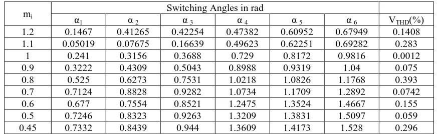
The following table 1. shows the variation of switching angles (in rad) and VTHD(%) with modulation index.
mi
Switching Angles in rad
α1 α 2 α 3 α 4 α 5 α 6 VTHD(%)
1.2 0.1467 0.41265 0.42254 0.47382 0.60952 0.67949 0.1408
1.1 0.05019 0.07675 0.16639 0.49623 0.62251 0.69282 0.283
1 0.241 0.3156 0.3688 0.729 0.8172 0.9816 0.0012
0.9 0.3222 0.4309 0.5043 0.8988 0.9319 1.04 0.075
0.8 0.525 0.6273 0.7531 1.0218 1.0826 1.1768 0.393
0.7 0.7124 0.8828 0.9282 1.0734 1.1709 1.2892 0.0742
0.6 0.677 0.7554 0.8521 1.2475 1.3524 1.4667 0.155
0.5 0.7246 0.8323 0.9263 1.3209 1.3831 1.5097 0.059
0.45 0.7332 0.8439 0.944 1.3609 1.4173 1.528 0.296
Table 1. Multiple set of switching angles (in rad) at different modulation index for equal source voltage
The following table 2. shows comparison in between VTHD(31)(%) obtained by two different approaches for equal
source voltages at particular modulation index,
mi
VTHD(31) (%)
(1St approach)
VTHD(31) (%)
(2nd approach)
1.2 48.796 4.2251
1.1 23.923 5.2876
1 12.781 9.6336
0.9 44.8726 6.0771
0.8 19.6954 11.679
0.7 85.8726 13.144
0.6 33.6249 10.672
Table 2. Comparison of VTHD(31) (%) by two different approaches for equal source voltage
Blue— α1, Green— α2 ,Red— α3
Cyan— α4, Magenta— α5 Black— α6
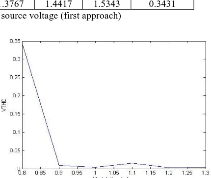
Fig 5. Variation of switching angles (in rad) with modulation index for equal source voltage (first approach) Fig 6. Variation of VTHD(%) with modulation index for
The variation of VTHD(31)(%) with modulation index in first and second approach for equal source voltage is shown in
fig 7.
Fig7. Comparison between VTHD(31) (%) by first and second approach (equal source voltage)
Case II: UN-EQUAL SOURCE VOLTAGES
The following table 3. shows the best solution set of switching angles (in rad) and corresponding variation of VTHD(%)
with modulation index.
Best Set of Solution
mi ρ α1 α2 α3 α4 α5 α6 VTHD(%)
1.3 1.2 0.5566 0.63611 0.77792 1.1069 1.1781 1.2379 0.0040
1.2 1.4 0.71012 0.80946 0.89634 1.2531 1.3493 1.4331 0.0021
1.1 1.4 0.72772 0.83752 0.93294 1.3206 1.3991 1.4878 0.0144
1 1.2 0.71556 0.818 0.90765 1.2833 1.3675 1.4763 0.0033
0.9 1.1 0.71955 0.82446 0.91578 1.2998 1.3736 1.4931 0.0083
0.8 1.1 0.73589 0.84726 0.94941 1.3767 1.4417 1.5343 0.3431
Table 3.Best set of solution for un-equal source voltage (first approach) Blue— VTHD(31) (1st approach)
Green— VTHD(31) (2nd approach)
Blue— α1, Green— α2 , Red— α3
Cyan— α4,Magenta— α5 Black— α6
Fig 8. Variation of switching angles (in rad) with modulation index at a particular voltage ratio for un-equal source voltage
(first approach)
Fig 9. Variation of VTHD(%) with modulation index at a
The following table 4.shows comparison in between VTHD(31) (%)obtained by two different approaches at particular
modulation index and voltage ratio.
mi ρ VTHD(31) (%)1st approach VTHD(31) (%)2nd approach
1.3 1.2 15.90 11.23
1.2 1.4 17.74 8.44
1.1 1.4 28.68 19.49
1 1.2 27.19 9.19
0.9 1.1 31.06 16.28
0.8 1.1 25.00 17.56
Table 4. Comparison of
V
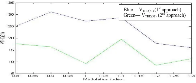
THD(31) (%) by two different approaches for unequal source voltageThe variation of VTHD(31)(%) with modulation index by first and second approach for un-equal source voltage is shown
in fig 10.
Fig 10. Comparison between VTHD(31) (%) by first and second approach for unequal source voltage
From the above analytical data and its graphical representation, it can be concluded that in between two approaches, the second approach considering up to 31st order of harmonics in the objective function is better than the first approach for both equal and unequal source voltages for maintaining lower system THD.
SIMULATION RESULTS
Thesimulation output waveform for equal source voltage along with harmonic spectrum at modulation index (mi=1) is
shown in fig(11-14):
EQUAL SOURCE VOLTAGE (FIRST APPRAOCH)
Blue— VTHD(31) (1st approach)
Green— VTHD(31) (2nd approach)
Fig 11. Per phase Output voltage waveform with equal source voltage (first approach) at mi=1
EQUAL SOURCE VOLTAGE(SECOND APPRAOCH)
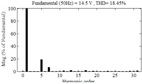
Thesimulation output waveform for un-equal source voltage along with harmonic spectrum at modulation index (mi=1.1, ρ=1.4) is shown in fig(15-18):
UN-EQUAL SOURCE VOLTAGE(FIRST APPRAOCH)
UN-EQUAL SOURCE VOLTAGE(SECOND APPRAOCH)
Fig 14. FFT of Output voltage wave form with equal source voltage (Second approach) at mi=1
Fig 13. Per phase Output voltage waveform with equal source voltage (Second approach) at mi=1
Fig 15. Per phase Output voltage waveform with un- equal source voltage (First approach) at mi=1.1,ρ=1.4
Fig 16. FFT of Output voltage wave form with un-equal source voltage (First approach) at mi=1.1, ρ=1.4
Fig 17. Per phase Output voltage waveform with un- equal source voltage (Second approach) at mi=1.1, ρ=1.4
COMPARISON BETWEEN VTHD(31)(%) IN BOTH THE CASE OF EQUAL AND UNEQUAL
SOURCE VOLTAGE BY TWO APPROACHES FROM SIMULATION RESULTS
Source type Modulation Index Voltage ratio VTHD(31) (%) by
First Approach
VTHD(31) (%)by
Second Approach
Equal 1 1.0 10.96% 9.90%
Unequal 1.1 1.4 27.57% 18.45%
Table 5. Comparison between VTHD(31) (%) by two approaches from simulation result
From the above simulation results it is concluded that the output voltage THD considering second approach is superior compare to first one. The same was also maintained in case of analytical results.
VI.CONCLUSION
In this study, Gravitational Search Algorithm has been implemented to eliminate lower order harmonics besides maintaining fundamental output voltage component of a cascaded multilevel inverter by using Selective Harmonic Elimination-Pulse Width Modulation technique. A 3 phase five-level cascaded multilevel inverter with quarter wave symmetry has been considered with both equal and unequal input DC link voltages and 5 low order dominant harmonics 5th, 7th, 11th, 13th and 17th was possible to eliminate with maintaining fundamental component. With the help of GSA, it was possible to find out the switching angles from nonlinear transcendental equation which exhibits multiple set of solutions. Advantage of proposed Gravitational Search Algorithm is its fast convergence in less time. This method is advantageous because after eliminating the low order harmonics, THD was maintained within the range of (0-1) % for both the cases. In between two approaches as mentioned earlier, second approach is found to be more efficient than first approach to maintain an overall low system THD. This also leads to reduce system switching loss maintaining an overall low THDwithout increasing the number of switching angle. In case of unequal source voltage, with higher modulation index, it was possible to vary voltage ratio more widely.
REFERENCES
[1] J. Rodriguez, J. S. Lai, and F. Z. Peng, ―Multilevel inverters: A survey of topologies, controls, and applications,‖ IEEE Trans. Ind. Electron., vol. 49, no. 4, pp. 724–738, Aug. 2002.
[2] L. M. Tolbert, J. N. Chiasson, D. Zhong, and K. J. McKenzie, ―Elimination of harmonics in a multilevel converter with nonequal dc sources,‖
IEEE Trans. Ind. Applicat., vol. 4, no. 1, pp. 75–82, Jan./Feb. 2005.
[3] P. N. Enjeti, P. D. Ziogas, and J. F. Lindsay, ―Programmed PWM techniques to eliminate harmonics: A critical evaluation,‖ IEEE Trans. Ind. Appl., vol. 26, no. 2, pp. 302–316, Mar./Apr. 1990.
[4] J. Sun and H. Grotstollen, ―Solving nonlinear equations for selective harmonic eliminated PWM using predicted initial values,‖ in Proc.Int. Conf. Ind. Electron., Control, Instrum., Autom., San Diego, CA, Nov. 1992, pp. 259–264.
[5] P. N. Enjeti and J. F. Lindsay, ―Solving nonlinear equations of harmonic elimination PWM in power control,‖ Electron. Lett., vol. 23, no. 12, pp. 656–657, Jun. 1987.
[6] T. Kato, ―Sequential homotopy-based computation of multiple solutions for selected harmonic elimination in PWM inverters,‖ IEEE Trans. Circuits Syst. I, Fundam. Theory Appl., vol. 46, no. 5, pp. 586–593, May 1999.
[7] John N. Chiasson, Leon M. Tolbert, Keith J. McKenzie,and Zhong Du, ―Control of a Multilevel Converter Using Resultant Theory,‖ IEEE TRANSACTIONS ON CONTROL SYSTEMS TECHNOLOGY, VOL. 11, NO. 3, MAY 2003.
[8] Tsorng-Juu Liang, Robert M. O’Connell, and Richard G. Hoft, ―Inverter Harmonic Reduction Using Walsh Function Harmonic Elimination Method‖, IEEE TRANSACTIONS ON POWER ELECTRONICS, VOL. 12, NO. 6, NOVEMBER 1997.
[9] Burak Ozpineci, Leon M. Tolbert,and John N. Chiasson, ―Harmonic Optimization of Multilevel Converters Using Genetic Algorithms‖, IEEE POWER ELECTRONICS LETTERS, VOL. 3, NO. 3, SEPTEMBER 2005.
[10] K. Sundareswaran, K. Jayant, and T. N. Shanavas, ―Inverter harmonic elimination through a colony of continuously exploring ants,‖ IEEE Trans.Ind. Electron., vol. 54, no. 5, pp. 2558–2565, Oct. 2007.
[11] V. G. Agelidis, A. Balouktsis, and I. Balouktsis, ―On applying a minimization technique to the harmonic elimination PWM control: The bipolar waveform,‖ IEEE Power Electron. Lett., vol. 2, no. 2, pp. 41–44, Jun. 2004.
[12] Y. Sahali and M. K. Fellah, ―Selective Harmonic Eliminated Pulse-Width Modulation Technique (SHE PWM) applied to Three-level Inverter / Converter,‖ IEEE 2003.
[13] Z. Du, L. M. Tolbert, and J. N. Chiasson, ―Active harmonic elimination in multilevel converters using FPGA control,‖ in Proc. IEEE WorkshopComput. Power Electron., Urbana-Champaign, IL, Aug. 2004, pp. 127– 132.
[14] Z. Du, L. M. Tolbert, and J. N. Chiasson, ―Active harmonic elimination for multilevel converters,‖ IEEE Trans. Power Electron., vol. 21, no. 2, pp. 459–469, Mar. 2006.
[16] Wanmin Fei,Xinbo Ruan and BinWu, ―A Generalised Formulation of Quarter Wave Symmetry SHE-PWM Problems for Multilevel Inverters,‖ IEEE Trans.Power Electron.,vol. 24,no. 7JULY 2009.
[17] Bill Diong, Hossein Sepahvand and Keith A. Corzine, ―Harmonic Distortion Optimization of Cascaded H-Bridge Inverters Considering Device Voltage Drops and Noninteger DC Voltage Ratios‖ IEEE Trans. Ind. Elctron., Vol. 60, no. 8, AUGUST 2013.
[18] W. Fei, B. Wu and Y. Huang , ―Half-wave symmetry selective harmonic elimination method for multilevel voltage source inverters‖ IET Power Electron., Vol. 4, Iss. 3, 2011.
[19] M. S. A. Dahidah and V. G. Agelidis, ―Selective harmonic elimination PWM control for cascaded multilevel voltage source converters: A generalized formula,‖ IEEE Trans. Power Electron., vol. 23, no. 4, pp. 1620– 1630, Jul. 2008.