Distributed Arithmetic based Hybrid architecture for
Discrete Transforms
DARSHAN KUMAR S
1, NIRMLA L
2VLSI Design and Embedded Systems, REVA University,Karnataka, India
School of ECE, Reva University,Karnataka, India
ABSTRACT
The Transforms like Discrete cosine transform, wavelet transform etc., finds application in various noise
reduction applications, data compression, transient event characterization and many other signal processing
applications. Implementation of hybrid architecture to compute discrete cosine transform and wavelet
transform is proposed in this paper. The architecture is developed using new distributed arithmetic which is
very efficient in implementing products without using multipliers and ROM storage . The present
architectures require large storage space and higher transmission bandwidth and operating frequency.
Proposed method is efficient in terms of frequency of operation and power consumption compared to other
hybrid architectures.
I.
INTRODUCTION
Traditionally DCT architectures designs uses convolutions. Next generation DCT architectures are based on lifting algorithms. Lifting-based architectures not only have lower computation complexity but also require less memory Compared to convolution-based techniques. DCT/DWT architectures are based on the modified lifting scheme or the flipping structure. Large temporal buffer and fewer pipeline stages in flipping structure lead to longer critical path delay[4] [6].
Advantages of New Distributed arithmetic:
Less power consumption Less hardware requirement Easy to implement
Network congestion can be avoided
Applications:
Digital Signal Processing (DSP) applications Data compression
Smoothing and image de-noising Fingerprint verification
Biology for cell membrane recognition, to distinguish the normal from the pathological membranes DNA analysis, protein analysis
Speech recognition
1.1 Mathematical derivation of Distributed Arithmetic:
Consider the following equation:
where Ak is fixed coefficient, and the X is the input data word.
If Ak and X are in 2's complement format , then Ak may be represented as
where Ai = 0 or 1 , i = N, N + 1 , . . . , M,
[A]- is crucial to distributed arithmetic since its structure can provide savings in hardware to implement the computations. It only consists of 0’s and l’s.
The computation of distributed arithmetic can be realized with shifting and addition. Overall, by using Distributed arithmetic, inner product of vectors (1) can be implemented with basic cells of adder [4].
1.2 Problem Definition
The present architectures require large storage space and higher transmission bandwidth and operating frequency. The method proposed is to overcome these problems. Traditionally DCT architectures designs uses convolutions. Next generation DCT architectures are based on lifting algorithms. Lifting-based architectures not only have lower computation complexity but also require less memory Compared to convolution-based techniques. DCT/DWT architectures are based on the modified lifting scheme or the flipping structure. Large temporal buffer and fewer pipeline stages in flipping structure lead to longer critical path delay.
II.
SYSTEM
ARCHITECTURE
Fig 1: Block Diagram of Proposed architecture
A hybrid architecture using New Distributed arithmetic for 1-D DCT and 1-D HWT is proposed in this work.
The controller module generates the intermediate enable signal based on t_select pin. If the t_select = 0, then enable =0 which will give DCT coefficients and if t_select =1 ,then enable = 1 which will give HWT coefficients. The adder matrix butterfly will provide intermediate outputs for each transform coefficient which is then fed to a 16x1 multiplexer. 8 samples are processed in parallel since the intermediate output is fed to eight 16x1 multiplexer. The select signal to the multiplexer is generated by the controller.
The multiplexer provides 1 output at a time which is fed to adder. The first input to the adder is initialized by 0 and the other input is fed from the multiplexer. It is then added and the output is left shifted by 1 bit and fed back to the adder. Other input then changed according to the control signal of the multiplexer. The add and shift operation is continued and the output for first 8 samples are obtained. The complete architecture is controlled by the controller. The inputs to the controller are clock signal, reset and t_select pin. The control signals generated by controller is ctrl. The controller starts generating controlling signals only when reset = 1. The enable signal will decide which transform to be obtained and it is fed to the adder butterfly. The ctrl signal is used in RAM as well as in 16x1 multiplexer. In RAM , this ctrl signal is provided to give a delay of 13 clock cycles between successive 8 samples whereas in 16x1 multiplexer it will act as a select signal to opt for an intermediate output from adder butterfly to be loaded to the adder.
RAM. 8 samples at a time is provided for processing. The remaining samples are loaded according to a control signal generated from the controller. An 8 point Haar wavelet matrix and an 8 point DCT matrix are considered for developing the architecture. Because of the usage of array of shared adders between the transforms hardware is optimized.
2.1 The Discrete Cosine Transform (DCT)
The discrete cosine transform (DCT) separates the image or audio source into spectral sub-bands of differing
importance with respect to the image's visual quality. Since it transforms a signal or image from the spatial domain to the frequency domain , the DCT is similar to discrete Fourier Transform.
The general equation for a 1D DCT is defined by the following equation:
and the corresponding inverse 1D DCT transform is simple F-1(u), i.e.:
where
The basic operation of the DCT is as follows:
The input image is N by M;
f(i,j) is the intensity of the pixel in row i and column j;
F(u,v) is the DCT coefficient in row k1 and column k2 of the DCT matrix.
For most images, much of the signal energy lies at low frequencies; these appear in the upper left corner of
the DCT.
Compression is achieved since the lower right values represent higher frequencies, and are often small -
small enough to be neglected with little visible distortion.
The DCT input is an 8 by 8 array of integers. This array contains each pixel's gray scale level;
8 bit pixels have levels from 0 to 255.
where
The output array of DCT coefficients contains integers; these can range from -1024 to 1023.
The DCT is regarded as computationally easier to implement and more efficient set of basis functions, given
a known input array size (8 x 8) can be pre-computed and stored. This involves simply computing values for a convolution mask (8 x8 window) that get applied. The values as simply calculated from the DCT formula.
The DCT is often used in high speed and real time applications, and often in portable systems that have
limited CPU computing ability. Hence it requires to be implemented in hardware as FGA in order to meet the real time constraints [1].
The discrete cosine transform (DCT) separates the image or audio source into spectral sub-bands of differing importance with respect to the image's visual quality. Since it transforms a signal or image from the spatial domain to the frequency domain , the DCT is similar to discrete Fourier Transform [6].
However one primary disadvantage of the Fourier transform over the DCT is that the former involves only real multiplications, which reduces the total number of required multiplications in DCT. Another advantage lies in the fact that for most images much of the signal energy lies at low frequencies, and are often small - small enough to be neglected with little visible distortion. The DCT does a better job of concentrating energy into lower order coefficients than does the DFT for image data. This characteristic of the DCT, referred to as energy compaction efficiency, along with other advantages resulted in the JPEG and MPEG standards adopting the DCT as a standard for image compression [2] [3] .
2.2 Wavelet Transform
Wavelet Transform is of two types,
Continuous Wavelet Transform results in higher number of samples than the input and gives more redundant information
Discrete Wavelet Transform results in lesser or same number of samples as that of the input and it gives the less redundant data
There are different sorts of wavelets such as, Haar wavelet
Morlet wavelet Daubechies wavelet
The wavelet transform utilized in this work is Haar Wavelet Transform (HWT).
2.3 Haar wavelet transform
Alfred Haar introduced the first wavelet system in the year 1910 . The major features of HWT is its simplicity, straight forwardness and speed of computation. Haar wavelet is not differentiable since it is considered to be inconsistent. A Haar wavelet is the simplest type of wavelet. In discrete form, Haar wavelets are related to a mathematical operation called the Haar transform. The Haar transform serves as a prototype for all other wavelet transforms. Like all wavelet transforms, the Haar transform decomposes a discrete signal into two sub-signals of half its length where one is a running average or trend and the other is a running difference or fluctuation [10] [11].
The Haar wavelet transform has a number of advantages:
It is exactly reversible without the edge effects that are a problem with other Wavelet transforms. It is memory efficient, since it can be calculated in place without a temporary Array
It is conceptually simple It is fast.
Fig 2: Simulation result wave forms
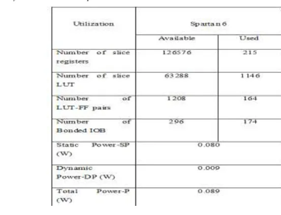
Hybrid architectures is then synthesized in Xilinx ISE 14.7 and post synthesis place and route(PAR) report is summarized in TABLE 1. Figure also shows the power consumption details of the hybrid architecture on the target devices Spartan 6 at a clock frequency of 50 MHz.
Resource utilization for the standalone architectures for DCT and HWT and the proposed hybrid architecture while synthesizing using Spartan 6 device is shown in figure. If the three transforms are implemented individually and the total hardware is compared against the hybrid architecture, the proposed architecture uses about 27% less adders, 40% less LUTs and 75% less registers compared to standalone units
TABLE 1: Synthesis and Power Report
III.
CONCLUSION
power consumption compared to standalone or other similar hybrid architectures. Proposed structure can operate at almost twice the frequency compared to the other architectures.
REFERENCES
[1] El Aakif, M., S. Belkouch, N. Chabini, and M. M. Hassani. "Low power and fast DCT architecture using multiplier-less method." In IEEE Faible Tension Faible Consommation (FTFC), pp. 63-66, 2011
[2] Hourani, Ramsey, Ishita Dalal, W. Rhett Davis, Christopher Doss, and Winser Alexander. "An efficient VLSI implementation for the 1D
convolutional discrete wavelet transform." In 51st Midwest Symposium on Circuits and Systems, pp. 870-873. 2008.
[3] Mankar, Abhishek, Narayan Prasad, and Ansuman Diptisankar Das."FPGA implementation of retimed low power and high throughput DCT core using NEDA." In 2013 IEEE Students Conference on Engineering and Systems (SCES), , pp. 1-4, 2013.
[4] Pan, Wendi, Ahmed Shams, and Magdy Bayoumi. "NEDA: a new distributed arithmetic architecture and its application to one dimensional
discrete cosine transform." In 1999 IEEE Workshop on Signal Processing Systems, (SiPS 9)., pp. 159-168,1999. [5] Winser AlexanderZ. Chen, M.H. Lee,‖ On fast hybrid source coding design‖, in Proc. of the International Symposium on Information
Technology Convergence, pp. 143–147, 2007
[6] Wei Zhang, Member, IEEE, Zhe Jiang, Zhiyu Gao, and Yanyan Liu, ―An Efficient VLSI Architecture for Lifting-Based Discrete Wavelet
Transform‖,IEEE Transactions on Circuits and Systems—II: Express briefs, vol. 59, no. 3, March 2012.
[7] Yuan-Ho Chen and Tsin-Yuan Chang,‖A High Performance Video Transform Engine by Using Space-Time Scheduling Strategy‖, IEEE
Transactions on very large scale integration (VLSI) systems, vol. 20, no. 4, pp: 655-664, April 2012
[8] Z. Liu, T. Arslan, T. Erdogan, A novel re-configurable low power distributed arithmetic architecture for multimedia applications, in Proc.
of the IEEE Design Automation Conference , pp. 908–913, 2007.
[9] Sun, Qing, Jiang Jiang, Yongxin Zhu, and Yuzhuo Fu. "A Re-configurable Architecture for 1-D and 2-D Discrete Wavelet Transform." In 2013 IEEE 21st Annual International Symposium on Field-Programmable Custom Computing Machines (FCCM), , pp. 81-84, 2013.
[10] K. Wahid, S. Shimu, M. Islam, D. Teng, M. Lee, S.-B. Ko,‖ Efficient hardware implementation of hybrid cosine-Fourier-wavelet transforms on a single FPGA‖, in Proc. of the IEEE International Symposium on Circuits and Systems, pp. 2325–2328, 2009
[11] Khan A. Wahid , M.A. Islam , Samia S. Shimu ,Moon Ho Lee , Seok-Bum Ko,‖ Hybrid Architecture and VLSI Implementation of the