A New Three-Phase Modular Type
Multilevel VSI
B. Nava Jeevan Reddy1, S. Nageswara Rao2
Assistant Professor, Dept. of EEE, SRK Institute of Technology, Vijayawada, Andhra Pradesh, India1
Assistant Professor, Dept. of EEE, SRK Institute of Technology, Vijayawada, Andhra Pradesh, India2
ABSTRACT:This paper presents a new design of a three-phase multilevel inverter (MLI). The proposed MLI can be used for the distributed power generation systems with low frequencymodulation (power frequency). The proposed MLI is a modular type and can extend the number of output levels with increasing the number of modules. Compared to the existing MLIs (Neutral point diode clamped MLI, Flying capacitor MLI and Cascaded H-Bridge MLI) the proposed MLI is consisting less number of power electronics switches and isolated DC voltage sources. The usage of reduced power electronic equipment may effect the harmonics and ripple content in the system output.
KEYWORDS:Modular type, Multilevel inverter, low frequency modulation, isolated DC voltage sources.
NOMENCLATURES:FC/L – components per pole voltage level, Npole – number of voltage levels per pole,
NC – capacitors count, ND – diodes count, NSW – switching devices count, NPS – DC power supplies count,
Ntsf – transformers count, NX – other additionally components count
I.INTRODUCTION
Recently, multilevel inverters (MLI) lave obtained great attention as a single stage inverter. Although, they require more number of equipment, but due to their advantages as generating output voltage with extremely low distortion factor (DS), low dv/dt, small output filter size, low electromagnetic interface (EMI), and low total harmonic distortion (THD), MLIs still have great attention[1-6]. Practically, all of these advantages appear strongly as the number of DC power sources increased as in the case of renewable energy systems. The general concept of MLIs is to utilize isolated DC sources or a bank of series capacitors to produce AC voltage waveforms with higher amplitude and near sinusoidal waveform. There are basically three types of MLIs named as neutral point diode clamped (NPC) MLI[7], flying capacitor (FC) MLI[8], and cascaded H-Bridge (CHB) MLI[9]. Almost all of them are suffering from increased components number per level, and complex control architecture. Among the different topologies for MLIs, they can be classified into two main categories as 1) single DC source inverter such as FC and NPC inverters; 2) multi DC sources inverter such as CHB inverter. While, multi DC sources inverter is divided into symmetrical and nonsymmetrical topologies. Principally, nonsymmetrical topologies produce more voltage levels compared to symmetrical topologies. Almost all of these topologies can be extended for more voltage levels by increasing the number of the primary configuration (basic cell).
Many topologies are presented in the last decade focusing on minimizing the basic multilevel topologies drawbacks. The author in [10] presented a topology named multilevel dc-link (MLDCL). It consists of a group of basic cells connected in series configuration. Each cell produces E or 0 voltage across the connected cells, there is a H-Bridge to change the polarity of the voltage. The required number of active switches for (m) output voltage level is (m+3) for the MLDCL inverter. However, this topology requires increased number of components compared to the conventional topologies, and high voltage stresses. In [11], the authors presented a topology named transistor-clamped H-bridge (TCHB). The primary cell can produce a five-levels per pole in the output voltage (+E, +(1/2)E, 0). However, it suffers also from the increased components counts, requirements of electrolytic capacitors, complex control methodology.
II.COMPARISION OF VARIOUS MLIs
A comparison strategy based on number of components per level factor (FC/L) has been discussed in this paper. This
factor is used to define the required components to produce one voltage level across the output pole. Therefore, it acts as a comparison tool that is describing how the different topologies of MLIs fully utilize their components. This factor is defined in (1). If this factor (FC/L) has a high value, this indicates that the inverter requires a more number of
components to produce one pole voltage level and vice versa. Therefore, the research target is to decrease this factor
/
=
(1)
The below table shows the computed (FC/L) factor for the conventional types of the multilevel inverters and the
introduced topologies in [10]-[30]. From this table, it is clear that the newtopology is presented in [14] records the lowest value for this factor and so it requires the smallest count of the components to produce the same voltage level number.
Presented in Npole NPS NSW ND NC Ntsf FC/L
[10] 3 3 18 0 0 0 7.0
5 3 15 12 6 0 7.2
[12] 3 6 12 0 0 0 6.0
[13] 3 1 9 12 2 0 8.0
[14] 17 1 48 0 12 0 3.6
[15] 3 1 24 0 6 0 10.3
[16] 3 1 28 0 0 3 10.7
[17]
(a) four-level 4 3 18 0 4 0 6.3
(b) five-level 5 3 24 0 4 0 6.2
(c) six-level 6 5 30 0 6 0 6.8
[18] 12 1 144 0 35 3 15.2
[19] 5 3 36 0 9 0 9.6
[20]
(a) the half-bridge based cell 3 1 12 0 6 0 6.3
(b) the full-bridge based cell 5 1 24 0 6 0 6.2
(c) the clamp-double 3 1 15 6 6 0 9.3
(d) the 3-level FC 3 1 12 0 6 0 6.3
(e) the 3-level NPC 3 1 12 6 6 0 8.3
(f) the 5-level cross-connected SM 9 1 36 0 12 0 5.4
[21]
(a) mixed commutation cells 4 1 18 0 6 0 6.3
(b) asymmetrical commutation cells 4 1 18 0 6 0 6.3
(c) cross connected commutation cells 5 1 24 0 6 0 6.2
(d) clamped double commutation cells 4 1 15 6 6 0 7.0
(e) T-connected NPC using RB switch 1 12 0 6 0 6.3
(f) alternative Active 3-L NPC 3 1 18 0 6 0 8.3
[22]
Hybrid MLIs topologies
6 7 30 0 0 0 6.2
[23] 7 8 36 6 0 0 7.1
[24] 6 13 30 0 0 0 7.2
[25] 3 4 12 0 0 0 5.3
[26] 3 6 12 0 0 0 6.0
[27] 4 3 11 20 0 0 8.5
[28] 5 3 18 24 6 0 10.2
[29] 5 6 24 0 0 0 6.0
[30] 5 6 24 0 0 0 6.0
III. PROPOSED MODULAR MLI
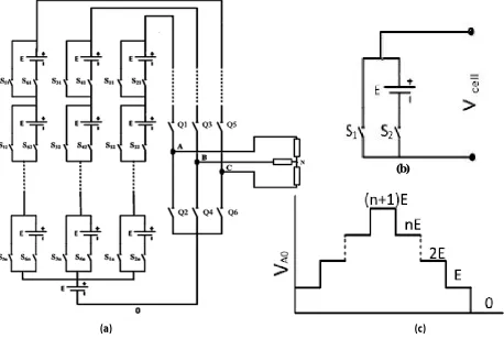
A new modular three-phase MLI with reduced components count is proposed and studied in this paper. The suggested three-phase modular inverter is shown in Fig. 1(a). Each phase arm consists of series connection of basic cells with a series connected switch, for example arm A is consists of one cell connected in series with switch Q1. Adding the common DC voltage source (E) in to each arm forms the pole, creating the pole voltages (VA0, VB0, VC0). In order to
obtain the zero state pole voltage another switch Q2 is added to the pole, similarly Q4 and Q6 for pole (B) and (C). Fig.1(b) shows the primary basic cell, where each cell consists of two switches S1, S2 and single dc voltage source. The two switches operate in a complementary fashion. Therefore, each cell can produce two voltage levels(0, E): when S1 in ON-STATE, zero voltage is produced across the cell terminals, and when S2 in ON-STATE, E volt is applied across the cell terminals. Furthermore, using only one cell per each pole and applying suitable control signals to theS1, S2, Q1 and Q2, fourvoltage levels per pole (i.e., 0, E/2, E, 2E) are produced. The output pole voltage for n cells connected in series configuration is shown in Fig.1(c).
Table II summarizes the different switching states and the corresponding output voltages for both the basic cell and the pole voltage (VA0) of the proposed MLI topology. The proposed topology is a modular type therefore it can be extended
to any levels. Equations (2)-(5) provide the relations of the proposed topology as
Npole = NCell + 2 (2)
MLevel = 2NCell + 3 (3)
NSW = 3(2NCell + 2) (4)
NPS = 3NCell + 1 (5)
Then for the example of NCell = 1, Npole = 3 [based on (2)] which is the pole voltage levels and MLevel = 5 [based on (3)]
which is the output line-to-line voltage levels. Note that the number of output phase voltage levels NPh will be derived
to be seven levels in low frequency modulation and nine levels for high frequency modulation.
(b)
(a) (c)
The above is the generalized power circuit of the proposed modular type MLI, each cell consists of a DC power supply connected in series with a power electronic switch. And it will be long shunted by another power electronic switch for controlling the input supply to the inverter circuit. The switching sequence of two cell switches and switches present in a single phase is given in below table. Based on the switching of these switches
Switching states
Switch Basic-unit Output
voltage Pole voltage (VA0)
S1 S2 Q1 Q2
1 ON OFF ON OFF 0 E/2
E
2 OFF ON ON OFF E 2E
3 OFF OFF OFF ON - 0
Table 2. Different switching states and the corresponding output voltages
III.SIMULATION AND RESULTS OF PROPOSED MLI
The proposed topology has been simulated using MATLAB software package tools. A single cell (NCell = 1) has been
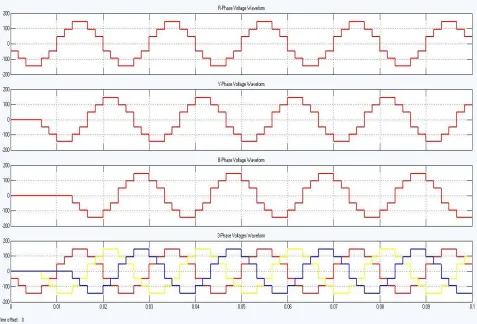
choose to produce five levels per line-to-line load voltages according to (3). However, the proposed topology can be extended to n cells. The three-phase inverter circuit is operated in normal 180o mode of conduction. Then the inverter output will be in the manner of 3 level (0, E/2, E) and by switching-ON the DC power supply present in series connected basic cell the output will be shifted to the fourth level (2E). Therefore, the final output of the proposed novel inverter circuit will be 4-level (0, E/2, E, 2E).
Fig 2 is the simulation output of proposed new modular type of multilevel inverter,time taken in sec on x-axis and voltages taken in terms of volts on y-axis. The fig.2 shows the individual phase voltages (VA0, VB0& VC0) of three
phase output and finally the three phase voltage waveform (VABC).
Fig.1 shows the generalized power circuit of the suggested three phase modular type MLI, a basic cell of the proposed MLI and pole voltage (VA0) waveform for theproposed converter with ‘n’ no. of cells. Table.1 is the comparison of components per pole voltage level(FC/L), for different multilevel inverters proposed in the references [10,
12-30]. And the table.2 is the different switching states of the proposed modular type MLI to get multilevel output.
VI.CONCLUSION
A novel modular multilevel inverter (MMLI) topology is presented. The proposed MLI has several advantages compared with existing MLIs topologies. A less number of components such as isolated dc-power supplies, power electronics switching devices, electrolyte capacitors and power diodes are required. So it exhibits the merits of high efficiency, lower cost, simplified control algorithm, smaller inverter's foot print and increased the overall system reliability. Due to the modularity of the presented topology, it can be extended to higher stages number leads to a good performance issues such as low dv/dt, low Electromagnetic Interference (EMI), and low Total Harmonic Distortion(THD) and eliminating the output filter will be obtained. The issue related to the cost of each component used in this topology is out of scope of this paper. The system simulation model and its control algorithm are developed using MATLAB software package tools to validate the proposed MLI topology.
REFERENCES
[1] S. J. Park, F. S. Kang, M. H. Lee, and C. U. Kim, “A new single-phase five-level PWM inverter employing a deadbeat control scheme,” IEEE Trans. Power Electron., vol. 18, no. 3, pp. 831–843, May 2003.
[2] V. G. Agelidis, D. M. Baker, W. B. Lawrance, and C. V. Nayar, “A multilevel PWM inverter topology for photovoltaic applications,” in Proc. Int. Symp. Ind. Electron., vol. 2, pp. 589–594,Jul. 1997.
[3] G. J. Su, “Multilevel DC-link inverter,” IEEE Trans. Ind. Appl., vol. 41, no. 3, pp. 848–854, May–Jun. 2005.
[4] M. Calais, L. J. Borle, and V. G. Agelidis, “Analysis of multicarrier PWM methods for a single-phase five level inverter,” in Proc. PowerElectron. Specialists Conf., vol. 3, pp. 1351–1356, 2001.
[5] C. T. Pan, C. M. Lai, and Y. L. Juan, “Output current ripple-free PWM inverters,” IEEE Trans. Circuits Syst. II, Exp. Briefs., vol. 57, no. 10, pp. 823–827, Oct. 2010.
[6] T. C. Neugebauer, D. J. Perreault, J. H. Lang, and C. Livermore, “A six-phase multilevel inverter for MEMS electrostatic induction micromotors,” IEEE Trans. Circuits Syst. II, Exp. Briefs, vol. 51, no. 2, pp. 49–56, Feb. 2004.
[7] A. Nabae, I. Takahashi, and H. Akagi, “A new neutral-point-clamped PWM inverter,” IEEE Trans. Ind. Appl., vol. IA-17, no. 5, pp. 518– 523, Sep. 1981.
[8] M. F. Escalante, J. C. Vannier, and A. Arzandé, “Flying capacitor multilevel inverters and DTC motor drive applications,” IEEE Trans. Ind. Electron., vol. 49, no. 4, pp. 809–815, Aug. 2002.
[9] M. Malinowski, K. Gopakumar, J. Rodriguez, and M. A. Pérez, “A survey on cascaded multilevel inverters,” IEEE Trans. Ind. Electron., vol. 57, no. 7, pp. 2197–2206, Jul. 2010.
[10] S. N. Rao, D. V. A. Kumar, and C. S. Babu, “New multilevel inverter topology with reduced number of switches using advanced modulation strategies,” in Proc. Int. Conf. Power, Energy Control, pp. 693–699, Feb. 2013.
[11] N. A. Rahim, M. F. M. Elias, and W. P. Hew, “Transistor-clamped H-bridge based cascaded multilevel inverter with new method of capacitor voltage balancing,” IEEE Trans. Ind. Electron., vol. 60, no. 8, pp. 2943–2956, Aug. 2013.
[12] H. Belkamel, S. Mekhilef, A. Masaoud, and M. A. Naeim, “Novel three-phase asymmetrical cascaded multilevel voltage source inverter,” IET Power Electron., vol. 6, no. 8, pp. 1696–1706, Sep. 2013.
[13] E. A. Mahrous, N. A. Rahim, and W. P. Hew, “Three-phase three-level voltage source inverter with low switching frequency based on the two level inverter topology,” IET Electric Power Appl., vol. 1, no. 4, pp.637–641, Jul. 2007.
[14] P. R. Kumar, R. S. Kaarthik, K. Gopakumar, J. I. Leon, and L. G. Franquelo, “Seventeen-level inverter formed by cascading flying capacitor and floating capacitor H-bridges,” IEEE Trans. Power Electron., vol. 30, no. 7, pp. 3471–3478, Jul. 2015.
[15] K. Ilves et al., “A submodule implementation for parallel connection of capacitors in modular multilevel converters,” IEEE Trans. Power Electron., vol. 30, no. 7, pp. 3518–3527, Jul. 2015.
[16] S. Essakiappan, H. S. Krishnamoorthy, P. Enjeti, R. S. Balog, and S. Ahmed, “Multilevel medium-frequency link inverter for utility scale photovoltaic integration,” IEEE Trans. Power Electron., vol. 30, no. 7, pp. 3674–3684, Jul. 2015.
[17] E. C. D. Santos, J. H. G. Muniz, E. R. C. d. Silva, and C. B. Jacobina, “Nested multilevel topologies,” IEEE Trans. Power Electron., vol. 30, no. 8, pp. 4058–4068, Aug. 2015.
[18] G. P. Adam, I. A. Abdelsalam, K. H. Ahmed, and B. W. Williams, “Hybrid multilevel converter with cascaded H-bridge cells for HVDC Applications: Operating principle and scalability,” IEEE Trans. Power Electron., vol. 30, no. 1, pp. 65–77, Jan. 2015.
[19] V. Dargahi, A. K. Sadigh, M. Abarzadeh, S. Eskandari, and K. A. Corzine, “A new family of modular multilevel converter based on modified flying-capacitor multicell converters,” IEEE Trans. Power Electron., vol. 30, no. 1, pp. 138–147, Jan. 2015.
[20] S. Debnath, Q. Jiangchao, B. Bahrani, M. Saeedifard, and P. Barbosa, “Operation, control, and applications of the modular multilevel converter: A review,” IEEE Trans. Power Electron., vol. 30, no. 1, pp. 37–53, Jan. 2015.
[22] S. Mekhilef and M. N. Abdul Kadir, “Voltage control of three-stage hybrid multilevel inverter using vector transformation,” IEEE Trans. Power Electron., vol. 25, no. 10, pp. 2599–2606, Oct. 2010.
[23] S. K. Chattopadhyay, C. Chakraborty, and B. C. Pal, “A hybrid multilevel inverter topology with third harmonic injection for grid connected photovoltaic central inverters,” in Proc. Int. Symp. Ind. Electron., pp. 1736–1741, May 2012.
[24] A. L. Batschauer, S. A. Mussa, and M. L. Heldwein, “Three-phase hybrid multilevel inverter based on half-bridge modules,” IEEE Trans. Ind. Electron., vol. 59, no. 2, pp. 668–678, Feb. 2012.
[25] M. Hasan, S. Mekhilef, and M. Ahmed, “Three-phase hybrid multilevel inverter with less power electronic components using space vector modulation,” IET Power Electron., vol. 7, no. 5, pp. 1256–1265, May 2014.
[26] A. Salem, E. M. Ahmed, M. Orabi, and A. B. Abdelghani, “Novel three-phase multilevel voltage source inverter with reduced no. of switches,” in Proc. Int. Renewable Energy Congr., pp. 1–5, Mar. 2014.
[27] J. Jamaludin, N. Abd Rahim, and H. Ping, “New three-phase multilevel voltage source inverter with low switching frequency,” in Proc. TENCON-IEEE Region 10 Conf., pp. 971–975, Nov. 2011.
[28] D. Baimel and S. Tapuchi, “A new topology of cascaded multilevel inverter,” in Proc. Int. Symp., pp. 137–140, Sep. 2013.
[29] R. N. A. L. Silva et al., “Five-level hybrid converter based on a Half- Bridge/ANPC cell,” in Proc. Power Electron. Conf., pp. 898–902, Sep. 2011.
[30] D. R. Caballero et al., “Cascaded symmetrical hybrid multilevel DC-AC converter,” in Proc. Energy Conversion Congr. Expos., pp. 4012–4019, Sep.12–16, 2010.
BIOGRAPHY
B. NavaJeevan Reddy was born in Guntur, Andhra Pradesh, India on 1989. He received his B.Tech degree from JNTUniversity, Hyderabad in 2011 and M.Tech degree from KL University in 2013. Later he joined as Asst.Professorin the department of Electrical & Electronics Engineering, SRK Institute of technology, Vijayawada, Andhra Pradesh, India. His interested research areas are Inverter circuits for renewable energy sources, Power Electronics controlled drives and Power converters for electric vehicles.