Low-Cost Inkjet-Printed Multiband Frequency-Selective Structures
Consisting of U-Shaped Resonators
¨
Ozg¨ur Eri¸s, Hande ˙Ibili, and ¨Ozg¨ur Erg¨ul*
Abstract—We present the design and computational simulation of multiband, polarization-independent, and thin frequency-selective structures for microwave frequencies and their fabrication via a very low-cost inkjet-printing procedure. The structures are constructed by periodically arranging unit cells that consist of U-shaped resonators, while polarization-independency is achieved by applying rotational arrangements. Various configurations are obtained by considering double and single U-shaped resonators, as well as rotational and complementary relationships between the corresponding unit cells on the top and bottom surfaces. We observe that complementary arrangements provide resonances with better quality, particularly by allowing the smaller resonators to operate as desired. Measurements on the fabricated samples demonstrate the feasibility of both effective and very low-cost inkjet-printed frequency-selective structures with multiband and polarization-independent characteristics.
1. INTRODUCTION
Recently, inkjet printing technology has attracted the interest of many researchers, as it enables fast, low-cost, and easy fabrication of many radio-frequency and microwave components [1–18]. Successfully fabricated samples of antennas [4, 7, 8, 12–14], radio-frequency identification tags [1, 2, 17, 18], metamaterials [5, 9, 10, 15, 16], as well as frequency-selective structures and surfaces [3, 6, 11] have been demonstrated in the literature, using both special material printers and conventional inkjet printers that are modified accordingly [12]. When employing very low-cost inkjet printing setups, which involve standard printers loaded with metal-based inks, fabrication errors need to be considered carefully, while these errors often put limitations in the design procedures [14]. Typical conductivity issues can partially be mitigated via post-processing (e.g., heat curing after printing), and very good flexibility can be achieved by selecting proper ink types (e.g., metal/liquid ratio) and substrates (e.g., the type of the photograph paper). It has been shown that flexible, very low-cost, and environmentally friendly components can be fabricated in such optimized fabrication setups [15], whereas the structures should still be carefully designed and often retuned due to the inherent limitations in printing resolution.
This study is devoted to the fabrication of thin, polarization-independent, and multiband frequency-selective structures (typically for 2–10 GHz band) that are suitable to be fabricated via very low-cost inkjet printing. Considering limited conductivity and printing resolution, these structures need to (1) be made of multiple (unconnected) elements that are easier to print, (2) be based on resonating structures, (3) preferably rely on first-order resonances of the elements, and (4) involve rotational arrangements and symmetry. Based on these design constraints, well-known U-shaped resonators [19–22] are ideal options to construct inkjet-printed frequency-selective structures, by arranging these resonators in array forms as large as desired. We note that using single-sized U-shaped resonators (identical resonators in the entire structure) can be sufficient to obtain resonances at multiple frequencies. In these cases, however, multiband operations rely on higher-order resonances of the elements, which may not be suitable for
Received 26 August 2019, Accepted 2 December 2019, Scheduled 20 December 2019
* Corresponding author: ¨Ozg¨ur Erg¨ul ([email protected]).
inkjet printing. Specifically, random fabrication errors introduced by very low-cost inkjet printing in resonator lengths may dramatically affect the quality of higher-order resonances that can be quite sensitive to electrical dimensions. More importantly, frequencies for bandstop and bandpass operations may not be easily selected using single-sized resonators. Consequently, we prefer to use resonators with different sizes together (e.g., two different dimensions in this paper), depending on the target frequencies. On the other hand, selection of resonator sizes alone is not sufficient to obtain high-quality resonances, i.e., good opaqueness and transparency properties at desired frequencies. As shown in this paper, positioning and orientation of resonators are of utmost importance to minimize performance degradation due to mutual couplings between elements.
In the following, we first briefly describe the in-house solver used for the design and simulation of the frequency-selective structures, as well as the very low-cost inkjet printing setup to fabricate them. Then, various designs and their performances are discussed, followed by comparisons of simulation and measurement results to demonstrate the effectiveness of the designed structures. The paper ends with our concluding remarks.
2. SIMULATION AND FABRICATION OF INKJET-PRINTED FREQUENCY-SELECTIVE STRUCTURES
The frequency-selective structures in this study involve periodic arrangements of U-shaped resonators. Each structure involves two layers (two-dimensional arrays of finite sizes) with a very short distance between them. For accurate simulations, we use a three-dimensional environment based on surface integral equations and their solutions via the method of moments. Using a frequency-domain solver, frequency-dependent responses of the structures are obtained by sampling the frequency, e.g., with 100– 200 MHz intervals for the simulations presented in this paper. The U-shaped resonators are modeled as perfect electric conductors with zero thicknesses, which can be formulated with the electric-field integral equation (EFIE). Dielectric effects are included simply by using effective medium parameters (permittivity values) for the surrounding media. Resonator surfaces are discretized by using triangles, on which the Rao-Wilton-Glisson (RWG) functions are defined to expand the induced electric current density. For the structures considered in the examples of this paper, discretizations involve as many as 30,000 triangles. Dense matrix equations are obtained by employing a Galerkin approach, i.e., using the RWG functions also for testing boundary conditions. The resulting matrix equations are solved iteratively, where the matrix-vector multiplications are accelerated by using the multilevel fast multipole algorithm (MLFMA) [23, 24]. Due to the inherent ill-conditioning of EFIE discretized with the RWG functions, as well as the resonant characteristics of the analyzed structures, the number of iterations can reach several thousands for a reasonable error threshold (e.g., 0.001), even when using the robust generalized minimal residual algorithm (GMRES). Therefore, we perform multilayer solutions [25], where MLFMA and its approximate forms are used in a multilayer (recursive) manner. Using a three-layer scheme, all problems shown in this paper require less than 60 flexible-GMRES (FGMRES) iterations, while the corresponding processing time is less than 1 hour per frequency in the MATLAB environment on a single core.
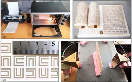
In this study, a very low-cost inkjet-printing setup is used to fabricate the designed structures. The general principles followed to construct this kind of fabrication processes can be found in [12, 14]. The setup involves commercial printers (Epson L130) that are manually modified, as depicted in Figure 1(a). Printers are loaded with a metallic ink (Metalon JS-B25P) that contains 25% silver. In the computer environment, pure black copies of the designed frequency-selective surfaces are used and directly sent to the printers, similar to printing a standard document. Layers are printed on HP professional glossy laser papers (125 g/m2). Then, to construct a frequency-selective structure, two layers are glued onto
(a) (b)
(d) (c)
Figure 1. Fabrication and test of frequency-selective structures involving U-shaped resonators. (a) Inkjet printer and standard oven for heat curing. (b) Printed samples (layers). (c) A focused view of printed U-shaped resonators. (d) Measurement setup involving two horn antennas.
and/or longer durations often result in disastrous effects, e.g., burned papers, cracks, and complete failures of conductivity. After a successfully applied heat curing, the end-to-end DC resistance of a large resonator becomes less than 3 Ω, while this value is typically thousands of Ohms without any curing.
3. DESIGNS OF FREQUENCY-SELECTIVE STRUCTURES
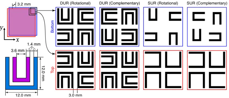
As mentioned above, U-shaped resonators are used in this study to construct polarization-independent and multiband frequency-selective structures. In the following discussions, four different (successful) structures among diverse alternatives are considered. As described in Figure 2, each of these structures consists of two layers with 3.2 mm distance between them (considering compactness, quality of resonances, and available fabrication material), while each layer contains 9×9 unit cells. As also illustrated in Figure 2, depending on the structure, a unit cell may involve four larger and four smaller resonators, four smaller resonators, or four larger resonators. The used types of U-shaped resonators are well known in the literature, and the larger resonators can be seen as scaled versions of those in [19]. Their dimensions are determined such that when being located in air (without substrate), they resonate at around 4.5 GHz. This main resonance is naturally followed by many higher-order resonances at the higher frequencies. The smaller resonators, which are not directly scaled but modified versions of the larger ones, are designed to resonate at around 7.0 GHz without substrate. Dimensions (arm lengths and widths) of these resonators are determined via parametric analyses. As shown in Figure 2, they can be placed inside the larger ones for compact designs, as practiced in the literature [20, 21].
y
x
Figure 2. Four different types of frequency-selective structures: Unit cells are shown for rotational and complementary arrangements of double U-shaped resonators (DURs) and single U-shaped resonators (SURs). Each frequency-selective structure involves two layers (top/bottom), each consisting of 9×9 unit cells.
• DUR [Rotational]: For this structure, both bottom and top layers contain unit cells with four larger and four smaller resonators, where the smaller resonators are placed inside the larger ones (i.e., forming double U-shaped resonators). The unit cells on the bottom and top layers have a rotational relationship, i.e., a bottom-layer (left-handed) cell can be obtained from a top-layer (right-handed) cell via a three-dimensional rotation (flip).
• DUR [Complementary]: This structure is similar to its rotational version, while the unit cells on the bottom and top layers are complementary, i.e., the corresponding resonators on the top and bottom layers are placed symmetrically (mirror symmetry). We note that, for this structure, a bottom/top-layer unit cell cannot be obtained from a top/bottom-layer unit cell via rotations. • SUR [Rotational]: For this structure, the unit cells on the bottom/top layers have a rotational
relationship. However, as opposed to DUR [Rotational], the bottom layer contains only smaller resonators, while the top layer contains only larger ones. In the context of inkjet printing, this type of eliminations can be useful to reduce metallization towards environmentally friendly and cheaper components, at the cost of reduced performance.
• SUR [Complementary]: This is the structure, which completes the set with complementary bottom/top unit cells and eliminated resonators.
As shown next, the complementary structures perform much better than the rotational ones, considering the quality of resonances and the obtained opaqueness/transparency.
>,W Z,W ϭ͘ϱϬͲϮ͘ϴϱ ',nj
ϯ͘ϬϬͲϰ͘ϯϱ ',nj
ϭϮ͘ϬϬͲϭϯ͘ϯϱ ',nj ϭϬ͘ϱϬͲϭϭ͘ϴϱ ',nj ϵ͘ϬϬͲϭϬ͘ϯϱ',nj ϳ͘ϱϬͲϴ͘ϴϱ ',nj ϲ͘ϬϬͲϳ͘ϯϱ ',nj ϰ͘ϱϬͲϱ͘ϴϱ ',nj
ϭϯ͘ϱϬͲϭϰ͘Ϯϱ ',nj
ͲϰϬ ͲϮϱ
;ĚtͬƐŵͿ
Ͳϯϱ ͲϯϬ ͲϰϬ ͲϮϱ
;ĚtͬƐŵͿ Ͳϯϱ ͲϯϬ
^hZ;ZŽƚĂƚŝŽŶĂůͿ
Figure 3. Near-zone power density in the vicinity of the SUR [Rotational] structure at different frequencies, when it is excited via LHCP and RHCP plane waves (1 V/m). Different colors represent values from−40 dBW/m2 to −25 dBW/m2. The structure is assumed to be located in vacuum.
ϭ͘ϱϬͲϮ͘ϴϱ ',nj
ϯ͘ϬϬͲϰ͘ϯϱ ',nj
ϭϮ͘ϬϬͲϭϯ͘ϯϱ ',nj ϭϬ͘ϱϬͲϭϭ͘ϴϱ ',nj ϵ͘ϬϬͲϭϬ͘ϯϱ',nj ϳ͘ϱϬͲϴ͘ϴϱ ',nj ϲ͘ϬϬͲϳ͘ϯϱ ',nj ϰ͘ϱϬͲϱ͘ϴϱ ',nj
ϭϯ͘ϱϬͲϭϰ͘Ϯϱ ',nj ͲϰϬ ͲϮϱ
;ĚtͬƐŵͿ
Ͳϯϱ ͲϯϬ ͲϰϬ ͲϮϱ
;ĚtͬƐŵͿ Ͳϯϱ ͲϯϬ >,W ^hZ;ŽŵƉůĞŵĞŶƚĂƌLJͿ Z,W
Figure 4. Near-zone power density in the vicinity of the SUR [Complementary] structure at different frequencies, when it is excited via LHCP and RHCP plane waves (1 V/m). Different colors represent values from−40 dBW/m2 to −25 dBW/m2. The structure is assumed to be located in vacuum.
For both rotational and complementary structures, similar responses to different polarizations are also remarkable.
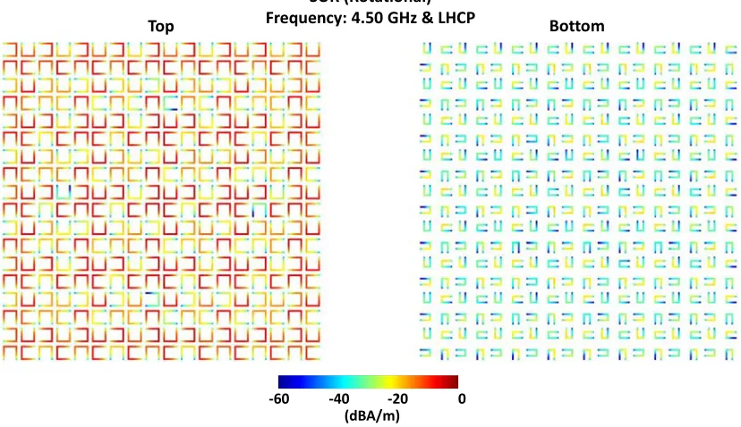
Examining the results in Figure 3, one may notice a weak response at around 6.9 GHz, which is actually related to the missing resonance of the SUR [Rotational] structure. In order to understand different responses of the rotational and complementary structures, Figures 5–8 further show the electric current density (in dBA/m) induced on the top and bottom layers of the structures at critical frequencies. Only LHCP is considered in these current-distribution plots since similar observations can be made for the RHCP excitation. The response of the SUR [Rotational] structure at 4.5 GHz is shown in Figure 5, where we observe strong resonances of the larger resonators (large electric current density values), while the smaller resonators act as parasitic elements. These strong resonances lead to the opaqueness of the structure at this frequency, as already shown in Figure 3. In Figure 6, we consider similar plots for the same structure at 6.75 GHz. Obviously, the smaller resonators become active at this frequency, while the larger resonators become parasitic elements. Nevertheless, such resonance effects are not actually visible in the near-zone power density plots (see Figure 3), and surprisingly, the structure remains almost transparent at around this frequency despite that its elements resonate strongly. In fact, none of the resonances in Figure 3 are related to the smaller resonators, i.e., all resonances of the SUR [Rotational] structure (as well as of the DUR [Rotational] structure) are related to the larger resonators whereas the smaller resonators act only as parasitic elements (and, in fact, not required in practice).
In comparison to the results in Figures 5 and 6, the corresponding plots for the
SUR [Complementary] structure are shown in Figures 7 and 8, respectively. In Figure 7, we observe strong resonances of the larger resonators at 4.35 GHz, leading to the opaqueness previously depicted in Figure 4. The smaller resonators of the SUR [Complementary] structure resonate at around 7.2 GHz as shown in Figure 8, which also induce a strong opaqueness. Hence, as opposed to those of the SUR [Rotational] structure that has a missing resonance, the smaller resonators of the SUR [Complementary] structure are actively used for frequency selection. For a close examination, Figure 9 presents the plots of the induced electric current density on single cells. In addition to the main resonances of the larger and smaller resonators (at 4.5/6.75 GHz for the rotational structure and
dŽƉ ŽƚƚŽŵ
^hZ;ZŽƚĂƚŝŽŶĂůͿ &ƌĞƋƵĞŶĐLJ͗ϰ͘ϱϬ',njΘ>,W
ͲϲϬ ͲϰϬ ͲϮϬ Ϭ
;ĚͬŵͿ
dŽƉ ŽƚƚŽŵ ^hZ;ZŽƚĂƚŝŽŶĂůͿ
&ƌĞƋƵĞŶĐLJ͗ϲ͘ϳϱ',njΘ>,W
ͲϲϬ ͲϰϬ ͲϮϬ Ϭ
;ĚͬŵͿ
Figure 6. Electric current density induced on the top and bottom layers of the SUR [Rotational] structure at 6.75 GHz, when it is illuminated by an LHCP plane wave. Smaller resonators are active at this frequency, while this is not visible in the near-zone characteristics. The structure is assumed to be located in vacuum.
dŽƉ ŽƚƚŽŵ
^hZ;ŽŵƉůĞŵĞŶƚĂƌLJͿ &ƌĞƋƵĞŶĐLJ͗ϰ͘ϯϱ',njΘ>,W
ͲϲϬ ͲϰϬ ͲϮϬ Ϭ
;ĚͬŵͿ
dŽƉ ŽƚƚŽŵ ^hZ;ŽŵƉůĞŵĞŶƚĂƌLJͿ
&ƌĞƋƵĞŶĐLJ͗ϳ͘ϮϬ',njΘ>,W
ͲϲϬ ͲϰϬ ͲϮϬ Ϭ
;ĚͬŵͿ
Figure 8. Electric current density induced on the top and bottom layers of the SUR [Complementary] structure at 7.2 GHz, when it is illuminated by an LHCP plane wave. Smaller resonators are active at this frequency. The structure is assumed to be located in vacuum.
ϰ͘ϱϬ',nj ϲ͘ϳϱ',nj ϭϬ͘Ϯ',nj
^hZ;ZŽƚĂƚŝŽŶĂůͿΘ>,W
ϰ͘ϯϱ',nj ϳ͘ϮϬ',nj ϵ͘ϵϬ',nj
^hZ;ŽŵƉůĞŵĞŶƚĂƌLJͿΘ>,W
ͲϲϬ ͲϰϬ ͲϮϬ Ϭ
;ĚͬŵͿ
Figure 10. Unit cells of the SUR [Rotational] and SUR [Complementary] structures, as well as of two intermediate structures that involve rotated (30◦ and 60◦) smaller resonators.
at 4.35/7.2 GHz for the complementary structure), higher-order resonances of the larger resonators are further shown (at 10.2 GHz for the rotational structure and at 9.9 GHz for the complementary structure). We observe that when the smaller resonators resonate, weak currents occur on the larger resonators for both rotational and complementary cases. Therefore, from the resonance point-of-view, the rotational and complementary arrangements are not very different. On the other hand, the complementary arrangement allows the smaller resonators to radiate effectively, since, in this arrangement, the active parts of the smaller resonators (where large currents occur) do not face metallic parts (of the larger resonators on the top layer). In the rotational arrangement, however, the active parts of the smaller resonators are all covered by the arms of the larger resonators, leading to poor radiation of the smaller resonators to induce a shadowing in the medium.
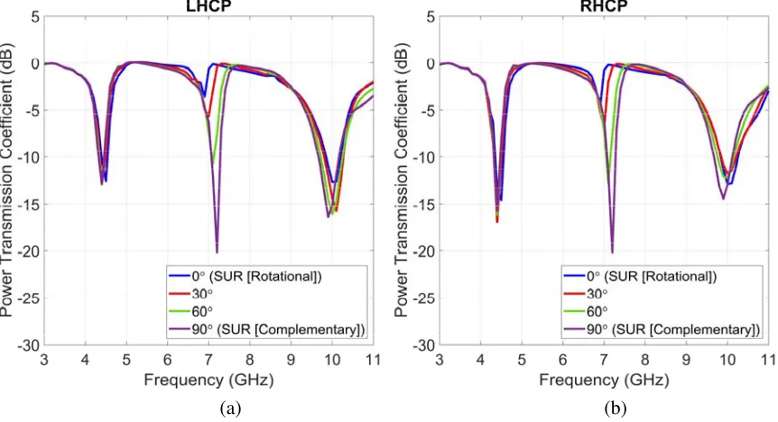
To further investigate significantly different electromagnetic responses of the structures with rotational and complementary arrangements, we consider a geometric transition from the SUR [Rotational] structure to SUR [Complementary] structure. As depicted in Figure 10, the SUR [Complementary] structure can be seen as a modified version of the SUR [Rotational] structure, when the smaller resonators (but not the unit cells) are rotated by 90◦. Hence, we consider two intermediate structures (both involving two layers of 9×9 unit cells), i.e., those with 30◦-rotated and 60◦-rotated smaller resonators, to observe how the orientation of these resonators significantly changes the overall transmission characteristics of the structures. Figure 11 presents the corresponding plots of the power transmission coefficient with respect to frequency from 3 GHz to 11 GHz. Both LHCP and RHCP excitations are considered, whereas similar responses are obtained for different polarizations. We observe that as the angle is changed from 0◦ (SUR [Rotational]) to 90◦ (SUR [Complementary]), the weak response at around 7 GHz becomes increasingly stronger, leading to the desired multiband characteristics at the end.
(a) (b)
Figure 11. Power transmission coefficient for the structures described in Figure 10. Both (a) LHCP and (b) RHCP illuminations are considered. The structures are assumed to be located in vacuum.
4. RESULTS
The four different frequency-selective structures designed and analyzed above are fabricated via the low-cost printing procedure described in Section 2 and tested in a measurement setup (see Figure 1). The fabricated samples (each involving two layers of 9×9 unit cells) cover 27 cm × 27 cm areas, whereas their thickness is smaller than 3.5 mm. In order to measure the power reflection coefficient, two standard horn antennas and a vector network analyzer (HP8720D) are used. For each structure, two measurements are performed in order to obtain the reflection coefficient values for LHCP and RHCP via postprocessing (from linear polarizations to circular polarizations). Measured values are compared with simulated values that are found by sampling the power density at the position of the receiver antenna and normalizing it with the incident power. In simulations, the effect of the paper substrate is included by an effective medium permittivity of 1.14, i.e., the metallic parts are assumed to be located in a homogeneous medium with 1.14 relative permittivity. As previously discussed in the context of antennas [14, 26], this effective value is found by fabricating simple dipole antennas (exactly as the frequency-selective structures) and matching the measured and simulated resonance frequencies.
Figure 12 presents the comparison of the simulated and measured power transmission coefficient values for the SUR [Rotational] structure. In addition to consistent results, we observe three resonances (low power transmission), all of which are related to the larger resonators, as discussed above. In both simulation and measurement results, the low quality of the second resonance is remarkable. The corresponding plots in Figure 13, which are related to the SUR [Complementary] structure, clearly show that the resonances can be dramatically improved by changing the unit-cell structure. In these plots, the second resonances that are related to the smaller resonators particularly demonstrate favorable properties of the complementary arrangement. One may also note that in both Figures 12 and 13, the discrepancy between the simulated and measured values increases with frequency, which seems related to the measurement errors (more specifically, poor performances of the used antennas at the higher frequencies).
(a) (b)
Figure 12. Simulated and measured power transmission coefficient for the SUR [Rotational] structure. Both (a) LHCP and (b) RHCP illuminations are considered.
(a) (b)
Figure 13. Simulated and measured power transmission coefficient for the SUR [Complementary] structure. Both (a) LHCP and (b) RHCP illuminations are considered.
(a) (b)
Figure 14. Simulated and measured power transmission coefficient for the DUR [Rotational] structure. Both (a) LHCP and (b) RHCP illuminations are considered.
(a) (b)
Figure 15. Simulated and measured power transmission coefficient for the DUR [Complementary] structure. Both (a) LHCP and (b) RHCP illuminations are considered.
5. CONCLUDING REMARKS
relationship enables the active usage of the smaller resonators, leading to multiband operations with good performances in terms of opaqueness and transparency. The obtained results clearly demonstrate the feasibility of very low-cost frequency-selective structures with useful electromagnetic responses for a plethora of applications.
ACKNOWLEDGMENT
This work was supported by the Scientific and Technical Research Council of Turkey (TUBITAK) under the Research Grant 118E243 and by the Turkish Academy of Sciences (TUBA) in the framework of the Young Scientist Award Program.
REFERENCES
1. Nikitin, P. V., S. Lam, and K. V. S. Rao, “Low cost silver ink RFID tag antennas,” Proc. IEEE Antennas and Propagation Soc. Int. Symp., 353–356, 2005.
2. Yang, L., A. Rida, R. Vyas, and M. M. Tentzeris, “RFID tag and RF structures on a paper substrate using inkjet-printing technology,” IEEE Trans. Microw. Theory Tech., Vol. 55, No. 12, 2894–2901, Dec. 2007.
3. Batchelor, J. C., E. A. Parker, J. A. Miller, V. Sanchez-Romaguera, and S. G. Yeates, “Inkjet printing of frequency selective surfaces,” Electron. Lett., Vol. 45, No. 1, 7–8, Jan. 2009.
4. Rida, A., L. Yang, R. Vyas, and M. M. Tentzeris, “Conductive inkjet printed antennas on flexible low-cost paper-based substrates for RFID and WSN applications,” IEEE Antennas Propag. Mag., Vol. 51, No. 3, 13–23, Jun. 2009.
5. Walther, M., A. Ortner, H. Meier, U. L¨offelmann, P. J. Smith, and J. G. Korvink, “Terahertz metamaterials fabricated by inkjet printing,”Appl. Phys. Lett., Vol. 95, No. 251107, Dec. 2009. 6. Cooper, J. R., S. Kim, and M. M. Tentzeris, “A novel polarization-independent, free-space,
microwave beam splitter utilizing an inkjet-printed, 2-D array frequency selective surface,” IEEE Antennas Wireless Propag. Lett., Vol. 11, 686–688, Jun. 2012.
7. Maza, A. R., B. Cook, G. Jabbour, and A. Shamim, “Paper-based inkjet-printed ultra-wideband fractal antennas,”IET Microwaves, Antennas&Propagation, Vol. 6, No. 12, 1366–1373, Sep. 2012. 8. Subbaraman, H., D. T. Pham, X. Xu, M. Y. Chen, A. Hosseini, X. Lu, and R. T. Chen, “Inkjet-printed two-dimensional phased-array antenna on a flexible substrate,” IEEE Antennas Wireless Propag. Lett., Vol. 12, 170–173, Mar. 2013.
9. Yoo, M., H. K. Kim, S. Kim, and M. M. Tentzeris, “Silver nanoparticle-based inkjet-printed metamaterial absorber on flexible paper,” IEEE Antennas Wireless Propag. Lett., Vol. 14, 1718– 1721, Apr. 2015.
10. Bin Ashraf, F., T. Alam, and M. T. Islam, “A printed xi-shaped left-handed metamaterial on low-cost flexible photo paper,”Materials, Vol. 10, No. 752, Jul. 2017.
11. Zabri, S. N., R. Cahill, G. Conway, and A. Schuchinsky, “Inkjet printing of resistively loaded FSS for microwave absorbers,” Electron. Lett., Vol. 51, No. 13, 999–1001, Jun. 2015.
12. C¸ ift¸ci, T., B. Karaosmano˘glu, and ¨O. Erg¨ul, “Low-cost inkjet antennas for RFID applications,” IOP Conf. Ser.: Mater. Sci. Eng., Vol. 120, No. 1, Apr. 2016.
13. G¨uler, S., B. Karaosmano˘glu, and ¨O. Erg¨ul, “Design, simulation, and fabrication of a novel type of inkjet-printed pixel antennas,” Progress In Electromagnetics Research Letters, Vol. 64, 51–55, 2016.
14. Mutlu, F., C. ¨Onol, B. Karaosmano˘glu, and ¨O. Erg¨ul, “Inkjet-printed cage-dipole antennas for radio-frequency applications,” IET Microwaves, Antennas & Propagation, Vol. 11, No. 14, 2016– 2020, Nov. 2017.
16. ˙Ibili, H., B. Karaosmano˘glu, and ¨O. Erg¨ul, “Demonstration of negative refractive index with low-cost inkjet-printed microwave metamaterials,”Microw. Opt. Technol. Lett., Vol. 60, No. 1, 187–191, Jan. 2018.
17. C¸ etin, E., M. B. S¸ahin, and ¨O. Erg¨ul, “Array strategies for improving the performances of chipless RFID tags,” Proc. IEEE Antennas and Propagation Soc. Int. Symp., 2018, 2015–2016.
18. Demir, M. A., F. Mutlu, and ¨O. Erg¨ul, “Design of highly distinguishable letters for inkjet-printed chipless RFID tags,” Proc. IEEE-APS Topical Conf. on Antennas and Propagation in Wireless
Communications (IEEE APWC), 783–786, 2018.
19. Li, Z., R. Zhao, T. Koschny, M. Kafesaki, K. B. Alici, E. Colak, H. Caglayan, E. Ozbay, and C. M. Soukoulis, “Chiral metamaterials with negative refractive index based on four “U” split ring resonators,”Appl. Phys. Lett., Vol. 97, No. 081901, Aug. 2010.
20. Ekmekci, E., Topalli K., T. Akin, and G. Turhan-Sayan, “A tunable multi-band metamaterial design using micro-split SRR structures,” Opt. Exp., Vol. 17, No. 18, 16046–16058, Aug. 2009. 21. Turkmen, O., E. Ekmekci, and G. Turhan-Sayan, “Nested U-ring resonators: A novel multi-band
metamaterial design in microwave region,” IET Microwaves, Antennas & Propagation, Vol. 6, No. 10, 1102–1108, Jul. 2012.
22. Bakir, M., K. Delihacioglu, M. Karaaslan, F. Dincer, and C. Sabah, “U-shaped frequency selective surfaces for single- and dual-band applications together with absorber and sensor configurations,” IET Microwaves, Antennas &Propagation, Vol. 10, No. 3, 293–300, Feb. 2016.
23. Chew, W. C., J.-M. Jin, E. Michielssen, and J. Song, Fast and Efficient Algorithms in
Computational Electromagnetics, Artech House, Boston, 2001.
24. Erg¨ul, ¨O. and L. G¨urel,The Multilevel Fast Multipole Algorithm (MLFMA) for Solving Large-Scale Computational Electromagnetics Problems, Wiley-IEEE, 2014.
25. Onol, C., A. ¨¨ U¸c¨unc¨u, and ¨O. Erg¨ul, “Efficient multilayer iterative solutions of electromagnetic problems using approximate forms of the multilevel fast multipole algorithm,” IEEE Antennas Wireless Propag. Lett., Vol. 16, 3253–3256, 2017.
![Figure 3.Near-zone power density in the vicinity of the SUR [Rotational] structure at differentfrequencies, when it is excited via LHCP and RHCP plane waves (1 V/m)](https://thumb-us.123doks.com/thumbv2/123dok_us/1909374.1250233/5.612.96.525.379.602/figure-power-density-vicinity-rotational-structure-dierentfrequencies-excited.webp)
![Figure 6. Electric current density induced on the top and bottom layers of the SUR [Rotational]structure at 6.75 GHz, when it is illuminated by an LHCP plane wave](https://thumb-us.123doks.com/thumbv2/123dok_us/1909374.1250233/7.612.105.520.437.690/figure-electric-current-density-induced-rotational-structure-illuminated.webp)
![Figure 8. Electric current density induced on the top and bottom layers of the SUR [Complementary]structure at 7.2 GHz, when it is illuminated by an LHCP plane wave](https://thumb-us.123doks.com/thumbv2/123dok_us/1909374.1250233/8.612.93.527.428.676/figure-electric-current-density-induced-complementary-structure-illuminated.webp)
![Figure 10. Unit cells of the SUR [Rotational] and SUR [Complementary] structures, as well as of twointermediate structures that involve rotated (30◦ and 60◦) smaller resonators.](https://thumb-us.123doks.com/thumbv2/123dok_us/1909374.1250233/9.612.116.502.82.325/figure-rotational-complementary-structures-twointermediate-structures-involve-resonators.webp)
![Figure 12. Simulated and measured power transmission coefficient for the SUR [Rotational] structure.Both (a) LHCP and (b) RHCP illuminations are considered.](https://thumb-us.123doks.com/thumbv2/123dok_us/1909374.1250233/11.612.91.527.372.610/simulated-measured-transmission-coecient-rotational-structure-illuminations-considered.webp)
![Figure 14. Simulated and measured power transmission coefficient for the DUR [Rotational] structure.Both (a) LHCP and (b) RHCP illuminations are considered.](https://thumb-us.123doks.com/thumbv2/123dok_us/1909374.1250233/12.612.107.510.352.573/simulated-measured-transmission-coecient-rotational-structure-illuminations-considered.webp)
