Design of MIMO Beamforming Antenna Array for Mobile Handsets
Ting Li and Wen Geyi*
Abstract—A new design idea of MIMO beamforming antenna array for compact and thin handheld devices is investigated, where the beamforming function is used for transmitting and the MIMO function for receiving. The new design idea is illustrated by an antenna array consisting of eight printed planar inverted-F elements operating at GSM1900 (1880–1920 MHz) and LTE2300 (2300–2400 MHz). The 8-element antenna array is printed on an FR4 substrate of dimensions 136 mm×68.8 mm×1 mm. By using the radiation pattern diversity, good isolations, envelope correlation coefficients and mean effective gains are achieved for MIMO receiving. To realize the beamforming function when the antenna is used for transmitting, an optimal feeding mechanism is introduced by the method of maximum power transmission efficiency, which is then implemented by a continuously adjustable feeding circuit board. With the optimized feeding mechanism, the gain of the antenna array in the desired direction can be significantly enhanced. The effects of the human body on the performance of antenna array are also examined, and the results indicate that the proposed design still exhibits good MIMO and beamforming performances in a practical scenario.
1. INTRODUCTION
With the fast development of wireless technologies, new standards are gradually introduced to meet the increasing demands for high quality services. In addition to the existing standards and mature commercial applications, such as GSM, long term evolution (LTE), and 4G LTE [1, 2], industrial and academic researchers have also begun to focus on new technologies for mobile handset in recent years [3– 5].
Multi-antenna technologies integrated into handheld devices for 4G and 5G communications have been extensively investigated [6–16]. The multiple-input multiple-output (MIMO) system has emerged as one of the most promising technologies to increase the capacity of the wireless link. A compact planar multiband 4-element MIMO antenna system with high isolation for 4G/LTE and WLAN mobile phone applications is developed in [10], which operates in the frequency range of LTE band 1 (1920– 2170 MHz), 2 (1850–1990 MHz), 3 (1710–1880 MHz), 7 (2500–2690 MHz), 40 (2300–2400 MHz), and WLAN 2.4 GHz band. An 8-port dual-polarized antenna array in 2.6 GHz band is proposed for 5G smartphone applications in [12], which is composed of four uniform square loop radiating strips excited by two orthogonally coupled feeding strips. A dual-band MIMO antenna array operating at 3300– 3600 MHz and 4800–5000 MHz for 5G smartphone is discussed in [15], where the antenna is perpendicular to the edge of the system circuit board and is suitable for the popular full-screen mobile phone. A 12-port hybrid antenna array, consisting of three different antenna elements and operating in the LTE 42 (3400–3600 MHz), 43 (3600–3800 MHz), 46 (5150–5925 MHz) for 5G massive MIMO application, is studied in [16], and the effects of hand phantom on the performances of the antenna in the data and read modes are also investigated.
Received 8 March 2019, Accepted 13 June 2019, Scheduled 9 July 2019 * Corresponding author: Wen Geyi ([email protected]).
Except the MIMO techniques, the beamforming technique has also been considered promising for future handheld devices. The beamforming technique uses multiple antennas to direct electromagnetic field energy in desired directions with enhanced gain and therefore better signal coverage and higher data rate [17–19]. Several beamforming architectures have been reported in [20–24]. In [20], a 4-element smart antenna system has been designed, which uses a normal inverted-F antenna element of height 4 mm with two ground pins and operates at GSM-900 and PCS-1900 for handheld devices. A novel beam steering array with eight elements on each side of a mobile device for 5G applications, operating at 28 GHz, has been studied in [23]. The proposed array antenna has demonstrated good beam steering characteristics in different scanning angles, both in free space and after considering the user’s hand effects.
Recently, several massive MIMO beamforming systems have been investigated for wireless communication systems [24–26], where the MIMO technique and beamforming technique are combined, and are used at both ends of wireless communication systems. The combined designs take full advantage of the two different techniques and can achieve wider transmitting bandwidth, faster data rate, higher antenna gain, and better signal coverage. However, the available space in a handset is very limited, and the increasing number of antenna elements will inevitably lead to degradation of MIMO performance due to stronger mutual couplings. For this reason, applying massive MIMO beamforming techniques to handheld devices is still a challenge.
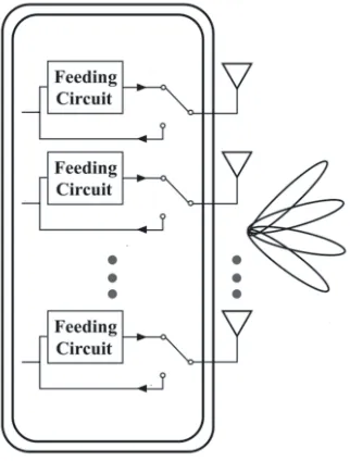
In order to apply the beamforming and MIMO techniques to a mobile handset with limited available space, we propose a new approach in this paper that uses the beamforming technique for transmitting and the MIMO technique for receiving, both sharing the same multi-antenna system. A simplified block diagram of the system using the idea is illustrated in Fig. 1. The multi-antenna array is first designed to achieve MIMO function in receiving mode, and the beamforming function in transmitting mode is then realized by a feeding circuit without changing the structure of the antenna array so that the MIMO function remains intact when the system is switched to receiving mode. In this paper, we will use an 8-element antenna array to demonstrate the above design concept. The antenna element is a printed planar inverted-Fantenna (PIFA), which covers GSM1900 (1880–1920 MHz) and LTE2300 (2300–2400 MHz). The MIMO function is achieved by properly designing the geometry of the antenna element and array configuration, while the beamforming function is realized by properly feeding the antenna array without further modifying the antenna elements and array configuration. To ensure that a maximum possible gain is guaranteed in the scanning range of the antenna system, the method of maximum power transfer efficiency (MMPTE) introduced in [27, 28] is used to determine the distribution
of excitations for the transmitting antenna elements, which is then realized by a feeding circuit. To examine the performances of the design in various scenarios, the distribution of excitations for the 8-element array is optimized for applications in free space as well as with a human phantom. The simulations and measurements indicate that the multi-antenna array meets the performance criteria for MIMO antenna system in a handset and demonstrates an excellent beam steering capability in both azimuth and elevation angles.
2. ANTENNA DESIGNS AND RESULTS
2.1. Design of the Antenna Array
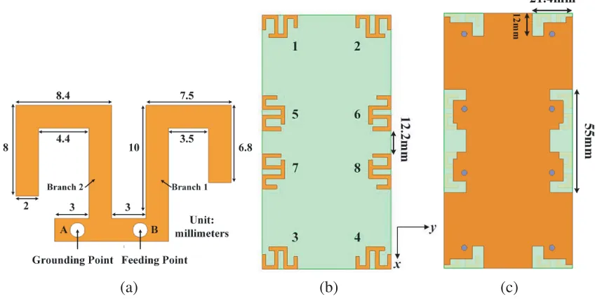
Since the antenna array is to be used for both MIMO and beamforming functions, the antenna elements and their configuration must be carefully selected so that both functions can be fulfilled with best possible performances. For the MIMO system in a handset, the diversity performance is determined by many factors related to antenna designs, such as the geometry of the antenna elements, polarization, separations among the elements, and array configuration. When the system is in the receiving mode for MIMO operation, the incoming signals come from different directions due to multipath propagations. For this reason, the pattern diversity is a more effective option for achieving diversity performance than other options such as spatial diversity and polarization diversity. Considering the fact that the MIMO performances are very sensitive to the antenna geometry and array configuration, the first step in our design is to optimize antenna element geometry and array configuration to meet the MIMO performance requirements while the beamforming function will be realized by an independent feeding mechanism as a second step in our design. As an example, a low profile printed 8-element antenna array system has been designed to illustrate the above procedure. The printed antenna array is designed on an FR4 substrate with relative dielectric constantεr = 4.4 and loss tangentδ = 0.02. Since the antenna array is set to use in the handset, the dimensions of the substrate are selected to be 136 mm×68.8 mm×1 mm, which are typical for smart phones. The detailed dimensions of the antenna element are illustrated in Fig. 2(a), where A is the grounding point, and B is the feeding point.
The antenna element is a PIFA with two resonating branches, 1 and 2. The lower frequency band (GSM1900) is controlled by both branches 1 and 2, and the high frequency band (LTE2300) is mainly controlled by branch 2. The configuration of the 8-element antenna array is shown in Fig. 2(b). Four
(a) (b) (c)
antenna elements, 1, 2, 3, and 4, are symmetrically placed at the corner of the PCB. By simulation, it is easy to find that the antenna elements at the four corners have strong radiation alongx-direction, which may increase the coupling between antenna elements at the corners and those in the middle. For this reason, the antenna elements in the middle are positioned in such a way so that they are perpendicular to the antennas at the corners to reduce the mutual couplings. In order to increase the bandwidth and isolation among the antenna elements and improve the impedance matching, the ground of PCB is partially removed, and the details are shown in Fig. 2(c). Note that all simulations in this paper are based on Ansys HFSS (High-frequency Structure Simulator).
2.2. MIMO Performances
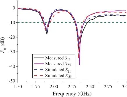
The simulated and measured reflection coefficients of antenna elements are shown in Fig. 3, and the impedance bandwidth measured at−10 dB covers the required frequency bands. The measured mutual couplings among antenna elements are shown in Fig. 4(a), and the mutual couplings in the required frequency bands are all lower than −10 dB, which meet the usual design criterion. Also note that no decoupling structures are used in our design. To seethe influences of the human body on the antenna performances, Fig. 4(b) gives the mutual couplings among the antenna elements when the phone is in talking position with the human phantom being present (Refer to Fig. 12). It can be seen that the
1.50 1.75 2.00 2.25 2.50 2.75 3.00 -50
-40 -30 -20 -10 0
Sii
(dB)
Frequency (GHz)
Measured S Measured S Simulated S Simulated S 11 55 11 55
Figure 3. Reflection coefficients of antenna elements.
1.50 1.75 2.00 2.25 2.50 2.75 3.00 -70
-60 -50 -40 -30 -20 -10 0
1.50 1.75 2.00 2.25 2.50 2.75 3.00 -70
-60 -50 -40 -30 -20 -10 0
(a) (b)
Sii
(dB)
Frequency (GHz) Frequency (GHz)
Sii
(dB)
Measured S 12
Measured S
Measured S
Measured S 13 15
57
Measured S 12
Measured S
Measured S
Measured S 13 15
57
human body affects the mutual couplings across the frequency bands. Some mutual couplings among antenna elements may become stronger while others become weaker, but all of them remain below
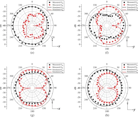
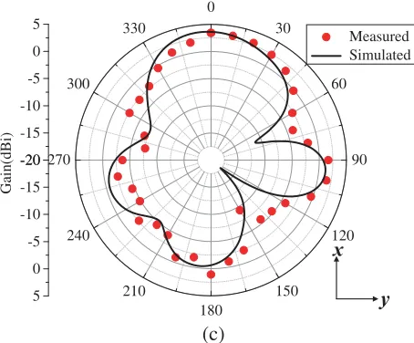
−10 dB across the frequency bands. The measured and simulated gain patterns for antenna elements 1 and 5 at 1.9 and 2.35 GHz are shown in Fig. 5. The radiation patterns are obtained under the condition that one element is excited with the rest being terminated in 50 Ω impedance.
Envelope correlation coefficient (ECC) and mean effective gain (MEG) are two important performance indices for MIMO systems. ECC is used to evaluate the diversity of MIMO system [29–32], which is usually required to be smaller than 0.5. In this paper, the ECC is determined by the radiation patterns [32]:
ρij =
Ω
Fi(θ, φ)·F¯j(θ, φ)dΩ
Ω
|Fi(θ, φ)|dΩ
Ω
|Fj(θ, φ)|dΩ
(1)
where the overbar denotes the complex conjugate; Fi(θ, φ) and Fj(θ, φ) are the 3D radiated fields of the antennas when theith andjth ports are excited; and Ω is the unit sphere. As shown in Fig. 6, the ECCs of the MIMO antenna system are all lower than 0.4 over the whole frequency bands in free space.
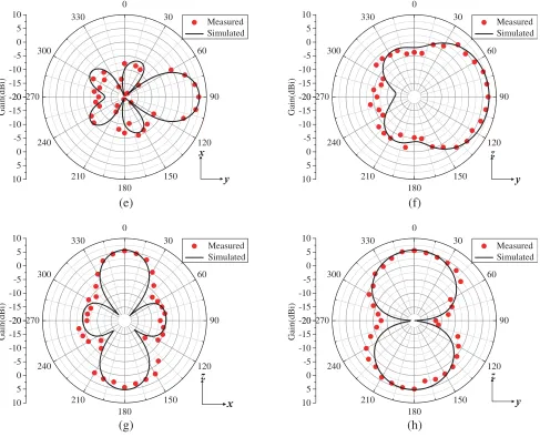
-40 -30 -20 -10 0 0 30 60 90 120 150 180 210 240 270 300 330 -40 -30 -20 -10 0 dB -40 -30 -20 -10 0 0 30 60 90 120 150 180 210 240 270 300 330 -40 -30 -20 -10 0 dB -40 -30 -20 -10 0 0 30 60 90 120 150 180 210 240 270 300 330 -40 -30 -20 -10 0 dB -40 -30 -20 -10 0 0 30 60 90 120 150 180 210 240 270 300 330 -40 -30 -20 -10 0 dB Measured G Measured G Simulated G Simulated G θ ϕ θ ϕ Measured G Measured G Simulated G Simulated G θ ϕ θ ϕ Measured G Measured G Simulated G Simulated G θ ϕ θ ϕ Measured G Measured G Simulated G Simulated G θ ϕ θ ϕ (e) (f) (g) (h)
Figure 5. Measured and simulated gain patterns for antenna elements 1 and 5 at 1.9 and 2.35 GHz. (a) Antenna 1 (1.9 GHz,xz-plane). (b) Antenna 1 (1.9 GHz,yz-plane). (c) Antenna 5 (1.9 GHz,xz-plane). (d) Antenna 5 (1.9 GHz, yz-plane). (e) Antenna 1 (2.35 GHz, xz-plane). (f) Antenna 1 (2.35 GHz,
yz-plane). (g) Antenna 5 (2.35 GHz, xz-plane). (h) Antenna 5 (2.35 GHz, yz-plane).
The MEG is defined as the ratio of the mean received power to the mean incident power of the antenna when moving the antenna over a random route. The MEG can be expressed by [33]:
MEG =
Ω
XPR·Gθ·pθ+Gϕ·pϕ
1 + XPR
dΩ, (2)
where Gθ and Gϕ are the θ and ϕ polarized components of the antenna power gain pattern; pθ and pϕ are the angular power density functions for the incident waves; XPR is the cross-polarization power ratio. Usually it is required that the MEG ratio for any two antenna elements is close to unity. In the case of a uniform propagation environment in which XPR = 1 andpθ=pϕ= 1/4π, Eq. (2) is simplified to [34]
MEG = et
2 (3)
1.50 1.75 2.00 2.25 2.50 2.75 3.00 0.0
0.1 0.2 0.3 0.4
ECC
ECC12
ECC15
ECC56
ECC57
Frequency (GHz)
Figure 6. ECCs of MIMO antenna system.
1.8 2.0 2.2 2.4 2.6
0.0 0.2 0.4 0.6 0.8 1.0
Total Efficiency
Top antenna
Frequency (GHz)
Middle antenna
Figure 7. Total efficiency of MIMO antenna system.
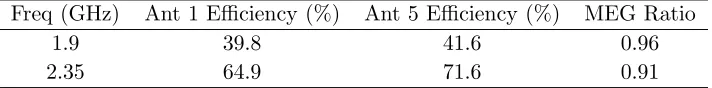
Efficiency is a key indicator of antenna radiation capability for higher order MIMO system (i.e., the number of antenna elements is greater than 2). The total efficiency and MEG ratio for antenna elements 1 and 5 at typical frequencies 1.9 and 2.35 GHz are listed in Table 1. The MEG ratios are 0.96 and 0.91, which satisfy the usual design criteria [35]. Fig. 7 shows that the total efficiencies of antennas 1 and 5 are both higher than 35% across the frequency bands.
Table 1. Total efficiency and MEG ratio.
Freq (GHz) Ant 1 Efficiency (%) Ant 5 Efficiency (%) MEG Ratio
1.9 39.8 41.6 0.96
2.35 64.9 71.6 0.91
3. OPTIMIZED EXCITATIONS FOR BEAMFORMING ARRAY
3.1. Design Method
The second step in our design is to achieve the beamforming function based on the MIMO array built in the previous section. To ensure that the MIMO array remains intact, and the MIMO performances do not change once the beamforming function is invoked, an independent feeding network will be built in such a way that the best beamforming performances can be realized without changing the geometry and the configuration of the original 8-element MIMO array.
As indicated in Fig. 5, the gain achieved by a single antenna element is very low. To enhance the gain, we introduce a feeding mechanism for the 8-element array, and the MMPTE will be used to determine the distribution of excitations as illustrated in [20, 22, 27, 28, 36–39]. The MMPTE is based on the fact that all wireless systems aim to maximize the power transmission efficiency between the transmitting and receiving antennas. Therefore, the power transmission efficiency may be considered as a natural performance index for antenna design. To direct the power to a desired direction, we may introduce a test antenna positioned in that direction. A power transmission system may then be formed by using n(n≤8) elements, selected from the 8-element antenna array, for transmitting and the test antenna for receiving, as illustrated in Fig. 8, which can be characterized as an (n+ 1)-port network.
Figure 8. Power transmission system.
input power to the transmitting antenna array
T = 1 2
|[br]|2− |[ar]|2
1 2
|[at]|2− |[bt]|2
,
where
[at] = [a1, a2,· · · , an]T, [ar] = [an+1],
[bt] = [b1, b2,· · · , bn]T, [br] = [bn+1]
respectively denote the incident and reflected waves for the transmitting antenna array and test receiving antenna. The incident and reflected waves are related by the scattering matrix as follows
[bt] [br]
=
[Stt] [Str] [Srt] [Srr]
[at] [ar]
.
Assume that all the antennas are matched. Then we have
T = ([A][at],[at]) ([at],[at]) ,
where (·,·) denotes the usual inner product of two column vectors; [A] = [Srt]T[Srt], and [Srt] denotes
the matrix of scattering parameters for the power transmission system and can be obtained by simulation tools such as Ansys high-frequency structure simulator (HFSS) or by measurements if the environment is too complicated to be simulated. When the power transmission efficiencyT is maximized, an optimized distribution of excitations for the multi-antenna array can be obtained, which satisfies the following eigenvalue equation
[A][at] =T[at]. (4)
Note that Equation (4) has a unique non-zero eigenvalue. When the antenna array is excited by the optimized excitations, the best possible gain is obtained in the desired direction.
3.2. Design of the Feeding Circuit
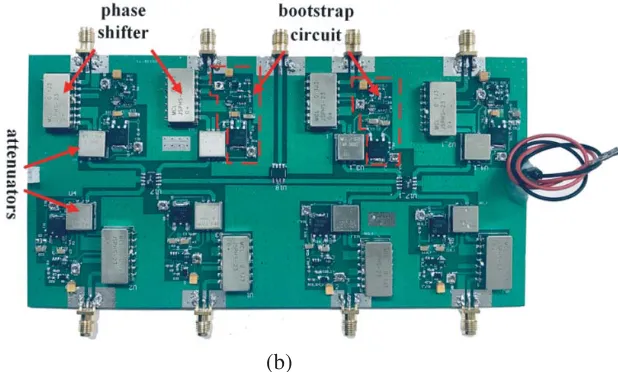
of excitations, an 8-port feeding circuit has been designed by using the low cost phase shifter and attenuator chips. Fig. 9 shows the schematic and a photo of the 8-port feeding circuit. The 8-way power divider is achieved by a two-way power divider followed by two 4-way power dividers to split the input RF signal into eight equal signals. The phase shifters are used to control the phase, and the attenuators are used to adjust the amplitude of the signal. A bootstrap circuit is utilized to reduce the current and keep the circuits voltages stable. By adjusting the slide rheostat on the circuit board to control the phase shifter and attenuator, the feeding circuit can achieve the optimized distribution of excitations. The antenna array is connected to the output of the feeding circuit to produce a directed beam in the prescribed direction. The loss of the feeding circuit has been taken into consideration while measuring the gain for different beamforming states.
Table 2. Distribution of excitations at 1.9 GHz.
Port NO. +x +y +z
1 0.34∠56 0.31∠−179 0.39∠−103 2 0.34∠−126 0.35∠50 0.41∠75 3 0.29∠133 0.29∠5 0.41∠−107 4 0.29∠−47 0.36∠−131 0.41∠76 5 0.16∠−104 0.24∠−70 0.29∠−177 6 0.15∠74 0.49∠179 0.29∠−1 7 0.53∠179 0.21∠107 0.31∠−178 8 0.52∠0 0.48∠0 0.29∠0
Table 3. Distribution of excitations at 2.35 GHz.
Port NO. +x +y +z
1 0.19∠1 0.33∠131 0.46∠−116 2 0.18∠−178 0.29∠−177 0.47∠64 3 0.53∠65 0.33∠−49 0.46∠−117 4 0.51∠−119 0.29∠3 0.47∠64 5 0.34∠171 0.15∠25 0.19∠179 6 0.32∠−8 0.54∠180 0.19∠1 7 0.29∠180 0.15∠−156 0.18∠−180 8 0.28∠0 0.54∠0 0.19∠0
(b)
Figure 9. Design of the feeding circuit. (a) The schematic. (b) The photo.
3.3. Results and Discussions
From the 8 elements of the array, one can choose n(n ≤8) elements to form a transmitting subarray with the rest terminated in matching loads. Table 4 gives the beamforming performances in positive x,
y, and z-directions with different numbers of antenna elements and different combinations of antenna elements forn= 4. It can be seen that the gain increases significantly as the number of antenna elements
Table 4. Achieved gain for different combinations of antenna elements at 2.35 GHz.
Antenna elements +x +y +z
1 −0.65 −3.48 0.3
1234 3.36 4.92 3.85
5678 2.49 4.41 2.9
1467 3.62 4.39 3.42
1–8 6.9 7.4 5.7
-20 -15 -10 -5 0 5
0
30
60
90
120
150 180
210 240 270
300 330
-20
-15
-10
-5
0
5
Gain(dBi)
Measured
-20 -15 -10 -5 0 5
0
30
60
90
120
150 180
210 240 270
300 330
-20
-15
-10
-5
0
5
(a)
(b)
Gain(dBi)
Simulated
-20 -15 -10 -5 0 5 0 30 60 90 120 150 180 210 240 270 300 330 -20 -15 -10 -5 0 5 (c) Gain(dBi) Measured Simulated
Figure 10. Measured and simulated radiation patterns of antenna array at 2.35 GHz in the xy -plane, directed to positive x-direction. (a) Elements {1,2,3,4}. (b) Element{5,6,7,8}. (c) Elements
{1,4,6,7}.
-20 -15 -10 -5 0 5 10 0 30 60 90 120 150 180 210 240 270 300 330 -20 -15 -10 -5 0 5 10 -20 -15 -10 -5 0 5 10 0 30 60 90 120 150 180 210 240 270 300 330 -20 -15 -10 -5 0 5 10 -20 -15 -10 -5 0 5 10 0 30 60 90 120 150 180 210 240 270 300 330 -20 -15 -10 -5 0 5 10 -20 -15 -10 -5 0 5 10 0 30 60 90 120 150 180 210 240 270 300 330 -20 -15 -10 -5 0 5 10 Measured Simulated Measured Simulated Measured Simulated Measured Simulated Gain(dBi) Gain(dBi) Gain(dBi) Gain(dBi) (e) (f) (g) (h)
Figure 11. Measured and simulated radiation patterns of 8-element antenna array. (a) xy-plane at 1.9 GHz. (b)xz-plane at 1.9 GHz. (c)xy-plane at 2.35 GHz. (d)xz-plane at 2.35 GHz. (e)xy-plane at 2.35 GHz. (f)yz-plane at 2.35 GHz. (g) xz-plane at 2.35 GHz. (h)yz-plane at 2.35 GHz.
increases. The measured and simulated radiation patterns of the 4-element subarray with beam directed to positive x-direction are shown in Fig. 10. The patterns are obtained under the condition that four elements are connected to the RF feeding circuit with the rest being terminated in matching loads.
The measured and simulated radiation patterns of the 8-elements antenna array (n= 8) with beam directed to the positive x,y, and z-directions at 1.9 and 2.35 GHz are shown in Fig. 11. Obviously, the radiation is greatly enhanced in the desired directions. The maximum gains in the positive x, y, and
z-directions respectively reach 7.7 dBi, 3.82 dBi, and 4.8 dBi at 1.9 GHz and 6.9 dBi, 7.4 dBi and 5.7 dBi at 2.35 GHz, which are significantly higher than previously reported results on handset antenna design.
4. IMPACT OF ENVIRONMENTS ON ANTENNA ARRAY
all these factors, which is difficult to handle even with the state-of-art simulation tools. Therefore, the experiments have to be resorted to attack the problem. We will use human body as an example to show how the influence of environments can be determined in general. The simulation with human body being present is not an easy task and very time consuming. For this reason, we set up a real environment measurement system by using a human phantom to simulate the phone operation in talking position,
Figure 12. Setup of measurement with human body.
Table 5. Optimized distribution of excitations.
Port NO. +z (2.35 GHz) 45◦ elevation (2.35 GHz) 45◦ elevation (1.9 GHz)
1 0.7∠−7 0.31∠−57 0.32∠−69
2 0.48∠−167 0.75∠169 0.64∠−141
3 0.17∠45 0.32∠−80 0.11∠95
4 0.26∠−92 0.31∠−15 0.42∠−41
5 0.18∠−97 0.21∠172 0.39∠115
6 0.32∠133 0.25∠−6 0.34∠−137
7 0.19∠16 0.21∠153 0.15∠−103
8 0.18∠0 0.1∠0 0.1∠0
-20 -15 -10 -5 0 5
0
30
60
90
120
150 180
210 240 270
300 330
-20
-15
-10
-5
0
5
-20 -15 -10 -5 0 5
0
30
60
90
120
150 180
210 240 270
300 330
-20
-15
-10
-5
0
5
Gain(dBi)
Measured
(a)
(b)
Measured
-20 -15 -10 -5 0 5
0
30
60
90
120
150 180
210 240 270
300 330
-20
-15
-10
-5
0
5
Measured
Gain(dBi)
(c)
Figure 13. Measured radiation patterns of 8-element antenna array. (a)yz-plane at 2.35 GHz, directed to positive z-direction. (b) yz-plane at 2.35 GHz, directed to 45◦ elevation. (c) yz-plane at 1.9 GHz, directed to 45◦ elevation.
as illustrated in Fig. 12. The 8-element antenna array is set as the transmitting antenna which is held by a hand model and placed near a head model, and a horn antenna is used as receiving antenna. By positioning the receiving horn in the desired direction in which the radiation needs to be enhanced, the scattering parameters can be obtained by a network analyzer which connects the transmitting array and receiving horn. Once the scattering parameters in the desired direction are determined, the optimized distribution of excitations can be found from Eq. (4). Table 5 shows the optimized distributions of excitations for the 8-element array operating at 1.9 and 2.35 GHz in positive z-direction and at 45◦ elevation, respectively.
The measured radiation patterns of the 8-element antenna array excited by the optimized distributions of excitations with human phantom being present are shown in Fig. 13. Clearly, the maximum radiation of the antenna array occurs in the desired directions. The realized peak gains in the corresponding directions indicated in Fig. 13 is 4.66 dBi, 4.66 dBi, and 3.5 dBi, respectively. Compared to the measured results in free space, the gain is reduced by about 1 to 2 dBi.
5. CONCLUSION
A new design idea for MIMO beamforming for handset application is discussed in this paper, in which the MIMO function is accomplished through properly designing the antenna elements, the array configuration as well as using pattern diversity, while the beamforming function is achieved by solely introducing an optimized feeding mechanism based on the method of maximum power transmission efficiency so that the MIMO performance remains unaffected while the beamforming function is summoned. A MIMO beamforming antenna array, operating at GSM1900 (1880–1920 MHz) and LTE2300 (2300–2400 MHz) for a compact and thin mobile handset, is proposed to validate the new design idea. The array uses 8 printed planar inverted-F antenna elements to achieve the beamforming function when the array is used for transmitting, and MIMO function when it is used for receiving. An 8-port feeding circuit is designed to realize the optimized distribution of excitations. The antenna array is tested in free space as well as with a human phantom, and excellent MIMO beamforming performances are observed in both situations.
ACKNOWLEDGMENT
REFERENCES
1. Dahlman, E., S. Parkvall, and J. Skold, 4G: LTE/LTE-advanced for Mobile Broadband, Academic Press, 2013.
2. Shajaiah, H., A. Abdel-Hadi, and C. Clancy, “Spectrum sharing between public safety and commercial users in 4G-LTE,” Int. Conf. Computing Networking Commun. (ICNC), 674–679, Honolulu, HI, USA, Feb. 2014.
3. Rappaport, T. S., et al., “Millimeter wave mobile communications for 5G cellular: It will work!,” IEEE Access, Vol. 1, 335–349, May 2013.
4. Dehos, C., et al., “Millimeter-wave access and backhauling: The solution to the exponential data traffic increase in 5G mobile communications systems?,” IEEE Commun. Mag., Vol. 52, No. 9, 88–95, 2014.
5. Silvia, S., H. Tabassum, and E. Hossain, “Multi-tier Drone architecture for 5G/B5G cellular networks: Challenges, trends, and prospects,” IEEE Commun. Mag., Vol. 56, No. 3, 96–103, Mar. 2018.
6. Wi, H., B. Kim, W. Jung, and B. Lee, “Multiband handset antenna analysis including LTE band MIMO service,” Progress In Electromagnetics Research, Vol. 138, 661–673, 2013.
7. Ilvonen, J., R. Valkonen, J. Holopainen, and V. Viikari, “Multiband frequency reconfigurable 4G handset antenna with MIMO capability,”Progress In Electromagnetics Research, Vol. 148, 233–243, 2014.
8. Hong, W., K. H. Baek, and S. Ko, “Millimeter-wave 5G antennas for smartphones: Overview and experimental demonstration,” IEEE Trans. Antennas Propag., Vol. 65, No. 12, 6250–6261, Aug. 2017.
9. Ban, Y. L., et al., “Small-size printed coupled-fed antenna for eight-band LTE/GSM/UMTS wireless wide area network operation in an internal mobile handset,” IET Microw. Antennas Propag., Vol. 7, No. 6, 399–407, Jun. 2013.
10. Ahmed, F., Y. Feng, and R. Li, “Dual wide-band four-unit MIMO antenna system for 4G/LTE and WLAN mobile phone applications,”2013 Loughborough Antennas Propag. Conf. (LAPC), 202–207, Loughborough, UK, Nov. 2013.
11. Khan, R., A. Abdullah Al-Hadi, and P. J. Soh, “Efficiency of millimeter wave mobile terminal antennas with the influence of users,” Progress In Electromagnetics Research, Vol. 161, 113–123, 2018.
12. Li, M. Y., et al., “Eight-port orthogonally dual-polarized antenna array for 5G smartphone applications,” IEEE Trans. Antennas Propag., Vol. 64, No. 9, 3820–3830, Sep. 2016.
13. Chen, Z. L., W. Geyi, M. Zhang, et al., “A study of MIMO antenna system for high order MIMO device,”Int. J. Antennas Propag., 2016.
14. Hussain, R., A. T. Alreshaid, S. K. Podilchak, and M. S. Sharawi, “Compact 4G MIMO antenna integrated with a 5G array for current and future mobile handsets,”IET Microw. Antennas Propag., Vol. 11, No. 2, 27–1279, Jan. 2017.
15. Zhang, W. J., Z. B. Weng, and L. Wang, “Design of a dual-band MIMO antenna for 5G smartphone application,”2018 Int. Workshop Antenna Technol. (iWAT), Nanjing, China, Jun. 2018.
16. Li, Y., Y. Luo, and G. L. Yang, “12-port 5G massive MIMO antenna array in sub-6 GHz mobile handset for LTE bands 42/43/46 applications,”IEEE Access, Vol. 6, 344–354, Oct. 2018.
17. Dinger, R. J., “A planar version of a 4.0 GHz reactively steered adaptive array,” IEEE Trans. Antennas Propag., Vol. 34, No. 3, 427–431, Mar. 1986.
18. Tsoulos, G. V., “Smart antennas for mobile communication systems: Benefits and challenges,” Electron. Commun. Engineering J., Vol. 11, No. 2, 84–94, 1999.
19. Dietrich, C. B., et al., “Smart antennas in wireless communications: Base-station diversity and handset beamforming,”IEEE Antennas Propag. Mag., Vol. 42, No. 5, 142–151, 2000.
21. Liang, G., W. Gong, H. Liu, and J. Yu, “Development of 61-channel digital beamforming (DBF) transmitter array for mobile satellite communication,” Progress In Electromagnetics Research, Vol. 97, 177–195, 2009.
22. Wan, W., G. Wen, and S. Gao, “Optimum design of low-cost dual-mode beam-steerable arrays for customer-premises equipment applications,”IEEE Access, Vol. 6, 16092–16098, Mar. 2018.
23. Yu, B., K. Yang, and G. L. Yang, “A novel 28 GHz beam steering array for 5G mobile device with metallic casing application,” IEEE Trans. Antennas Propag., Vol. 66, No. 1, 462–466, Jan. 2018. 24. Yang, B. Q., R. Q. Zhang, W. Hong, et al., “Digital beamforming-based massive MIMO transceiver
for 5G millimeter-wave communications,” IEEE Trans. Microw. Theory Techn., Vol. 66, No. 7, 3403–3418, May 2018.
25. Liu, X., et al., “Beam-oriented digital predistortion for 5G massive MIMO hybrid beamforming transmitters,” IEEE Trans. Microw. Theory Techn., Vol. 66, No. 7, 3419–3432, May 2018.
26. Jo, O., J. J. Kim, et al., “Exploitation of dual-polarization diversity for 5G millimeter-wave MIMO beamforming systems,” IEEE Trans. Antennas Propag., Vol. 65, No. 12, 6646–6655, Dec. 2017. 27. Wen, G., Foundations of Applied Electrodynamics, 273–275, Wiley, New York, NY, USA, 2010. 28. Wen, G., Foundations for Radio Frequency Engineering, 410–420, World Scientific, 2015.
29. Stein, S., “On cross coupling in multi-beam antennas,” IRE Trans. Antennas Propag., Vol. 10, No. 5, 548–557, 1962.
30. Blanch, S., J. Romeu, and I. Corbella, “Exact representation of antenna system diversity performance from input parameter description,”Electron. Lett., Vol. 39, No. 9, 705–707, May 2003. 31. Mikki, S. M. and Y. M. M. Antar, “On cross correlation in antenna arrays with applications to spatial diversity and MIMO systems,”IEEE Trans. Antennas Propag., Vol. 63, No. 4, 1798–1810, Apr. 2015.
32. Sharawi, M. S., A. T. Hassan, and M. U. Khan, “Correlation co-efficient calculations for MIMO antenna systems: A comparative study,”Int. J. Microw. Wireless Technol., 1–14, 2017.
33. Taga, T., “Analysis for mean effective gain for mobile in land mobile radio environments,” IEEE Trans. Vehicular Technol., Vol. 39, No. 2, 117–131, May 1990.
34. Karaboikis, M. P., et al., “Integrating compact printed antennas onto small diversity/MIMO terminals,” IEEE Trans. Antennas Propag., Vol. 56, No. 7, 2067–2078, 2008.
35. Ko, S. C. and R. D. Murch, “Compact integrated diversity antenna for wireless communications,” IEEE Trans. Antennas Propag., Vol. 47, No. 6, 954–960, Jun. 2001.
36. Shan, L. and G. Wen, “Optimal design of focused antenna arrays,”IEEE Trans. Antennas Propag., Vol. 62, No. 11, 5565–5571, Nov. 2014.
37. Cai, X., G. Wen, and H. C. Sun, “A printed dipole array with high gain and endfire radiation,” IEEE Antennas Wireless Propag. Lett., Vol. 16, 1512–1515, 2017.
38. Cai, X. and G. Wen, “An optimization method for the synthesis of flat-top radiation patterns in the near-field and far-field regions,” IEEE Trans. Antennas Propag., No. 2, Feb. 2019.