RTL validation methodology on high complexity wireless
microcontroller using OVM technique for fast time to market
Nurul Zhafirah Muhammad1, A. Harun1,2, N.A.M.A. Hambali1,2 , S. A. Z. Murad1, S. N. Mohyar1, M.N. Isa1, AB Jambek1
1School of Microelectronic, Universiti Malaysia Perlis, 02600 Arau Perlis 2Centre of Excellence for Advanced Sensor Technology (CEASTech)
Abstract. Increased demand in internet of thing (IOT) application based has inadvertently forced the move towards higher complexity of integrated circuit supporting SoC. Such spontaneous increased in complexity poses unequivocal complicated validation strategies. Hence, the complexity allows researchers to come out with various exceptional methodologies in order to overcome this problem. This in essence brings about the discovery of dynamic verification, formal verification and hybrid techniques. In reserve, it is very important to discover bugs at infancy of verification process in (SoC) in order to reduce time consuming and fast time to market for the system. Ergo, in this paper we are focusing on the methodology of verification that can be done at Register Transfer Level of SoC based on the AMBA bus design. On top of that, the discovery of others verification method called Open Verification Methodology (OVM) brings out an easier way in RTL validation methodology neither as the replacement for the traditional method yet as an effort for fast time to market for the system. Thus, the method called OVM is proposed in this paper as the verification method for larger design to avert the disclosure of the bottleneck in validation platform.
1 INTRODUCTION
1.1 The growth of integrated circuit
Over the last decade, rapid advancement in portable technology, wireless communication, audio, video and compact computers has drawn interest from electronic industry to venture themselves into the field of integrated circuit [1]. The growth in the integration density of microcontroller system followed closely the Moore’s Law. In articles of [2], the author presented Moore’s Law as a law that predicts that the number of transistors that can be placed on a single integrated circuit doubles about every two years.
Fig. 1. Moore’s Law [3]
the cloud and work downwards to see what chips are needed to support them such as power management and other silicon. This can be related to the introduction of sophistication on Internet-of-Things (IoT) which asserts that every object are connected to the internet and participating together in a system [5] as shown in the figure below.
Fig. 2. Visualize of Internet of thing’s application [6]
1.2 System-on-chip (SoC)
Hence, this has led to the advancements in the integrated circuit design in order to fulfill demand driven development by IoT solution, product requirement and potential intellectual property (IP) in the system. A well-known, the integrated circuit is a technology advancement that allows the integration of various parts to be put together into a chip such as digital and analog circuit, mix signal and others resulted in complexity of the chip and its design flow [7]. However, there is a limit to integrated circuit (IC) technology to allow only simple integrated transistor into a chip. Nevertheless, to overcome these limitation of integration, the large scale integration has been proposed such as system on chip (SoC) and wafer-scale integration (WSI) [7]. Even so, as the demand from clients to have technologies that allow the system to be able to integrate all the sophisticated electronic systems on a single chip tend the designers to design microcontroller based on system on chip (SoC), with the intension of reusing IP modules described in hardware description language (HDL) [8]. An example of these IP modules are microprocessors, digital signal processing, memory blocks, PLL and other peripherals as shown in Figure 2. Figure 3 shows that the SoC is designed based on AMBA bus design which comprised of ARM processors, ARM support modules, and memory [9]. Nowadays, the AMBA is one of the leading busing system used in high-performance SoC design that has been developed to become a family with different bus protocol such as ASB, APB, AHB, AXI and et al [9]. These IP then will be integrated together with the bus system to form the complex SoC. This is the starting point to start the validation process known also as a functional verification or validation. When choosing
methodology to follow for such platform validation, it is imperative to understand the requirement and the restriction a program had on the development to ensure the successful execution. This paper reviews the various methods used in SoC validation in the industry and proposes a suitable RTL validation methodology for wireless microcontroller system.
Fig. 3. Microcontroller based system on chip [10]
As presented in [11-13], the functional verification is divided into three methods: 1. Dynamic verification (simulation based), 2. Formal verification (static) and 3. Static Timing Analysis. However, in this paper the static timing analysis is not going too discussed in details because it is the method for full chip validation. This paper is organized as follows: An introduction is discussed in section 1, the methodology used is discussed in section 2 that divided by three subsection which is overview of the simulation will be presented in subsection 2.1, the formal verification methods are described in subsection 2.2 , while the recommended methodology by industry: hybrid technique is presented in subsection 2.3. Finally, section 3 summarizes the validation method available and propose the suitable validation methodology for wireless microcontroller at Register Transfer level.
2
Methodology
2.1. Simulation techniques
classification of simulators in three broad categories: HDL- based, schematic based, emulators and et al. However, in this paper focusing only on the HDL- based approaches to be applied for industrial environment. The HDL- based can be divided into two categories: event-driven simulator and cycle-based simulator [13]. Authors in [17-18] reported event-driven simulator operates by taking events, one at a time through the design until a steady state condition is achieved and any change in input stimulus is identified as an event. The design models include timing and functionality. Nevertheless, the event-driven simulator limited only for small design otherwise the speed of simulation becomes slow due to evaluation of output multiple times produced by this simulator [10] and [18-19]. Meanwhile, the approach by cycle-based simulator is introduced as the complementary of the limitation in event-driven simulator due to its ability for simulating very large designs. In articles of [17-18] and [20], the authors presented the cycle-based simulator which does not consider the time within clock cycle and only functions on synchronous logic circuit. There are some applications where this approach can be used [17], such as digital signal processing (DSP) chip, SoCs with processor and peripherals and others. Furthermore, the authors in [21] stated in his paper to use this approaches as one of simulators in performance evaluation and validation of microprocessor. This cycle-based simulator can be used also by combining it with other techniques: Decision diagram (DD) in order for achieving significant speed up of the simulation execution [22]. This DD techniques is used for representing the function of a design at RT and behavioral level. On the other hand, the author in [23] presented activity cycle diagrams (ADC) for modelling construction process using activities as the basic element into an equivalent executable Simulation Language for Alternative modelling (SLAM) [24] simulation model. Even so, the cycle based simulators also has a limitation for cannot detect glitches in the design and do not take the timing of design into consideration resulted the simulator to be performed using static timing analysis tool [19]. There are few of commercial tools provided by EDA to support the simulation for both techniques [13]: Verilog-XL (Verilog) Cadence, Sciriccor (VHDL) Synopsys, VCs (Verilog) Synopsys and others. Even though, the simulation is easy, flexible and economical, the simulation speed is extremely slow causing the simulation times became unreasonably long. Hence, the simulation using emulator is suggested to overcome the limitation [11].
Emulator is where the design is mapped into FPGA hardware for prototype simulation [13]. This stage is known as co-emulation: when hardware and software are simulated simultaneously [11]. The emulators are pre-packaged prototyping FPGA arrays that offer comparatively high debug visibility and run faster than simulator [25]. In [26], the authors presented four modes of simulation which can occur: RTL-FPGA co-simulation, SystemC-FPGA, Vector prototyping and In-circuit prototyping. However, there is still a continuous debate about FPGA prototyping versus emulation.
Hence, in [27], the authors stated that FPGA prototyping addresses mostly validation of smaller design or a single IP while emulation is being used for large SoC designs. Nevertheless the authors in [28] reported that FPGA can be also uses as a basic for software development, hardware development, etc. as long as before the final silicon is available. In addition, FPGA prototyping is a method to prototype SoC on FPGAs for hardware verification and early software development [28].
2.2 Formal verification
The formal techniques show the correctness of a design by providing analytical proofs. This methodology is being introduced in validation methodology because not all the modules are well suited for simulations techniques. In [29], the authors presented the formal technique adopted by Brazil Semiconductor Technology Center (BSTC) which further divide into three additional techniques: model checking, theorem proving and equivalence checks.
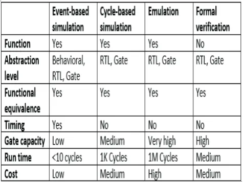
Model checking is an important technique for verifying sequential. In this technique, the authors in [30] mentioned that the specification of a design is expressed in temporal logic and the implementation is designed as finite state machine. This technique has two main approaches that have been presented [30]: SAT – based and BDD-based. BDD-based [31-32] is a canonical form for Boolean expressions which is used to symbolically represent the set of states. This approach is capable of handling system with hundreds of state variables causing no space efficient variable ordering [31]. Fortunately, the SAT- based approaches is more recommended by researcher due to its potential to handle much larger design [31]. Same goes to the equivalence checking, there are approaches that have been presented such as equivalence checking using cuts and heap [32] and Boolean reasoning for equivalence checking [33]. The various verification techniques offer different advantages
and features.Table 1 shown the comparison between the
verification techniques discussed above.
2.3 Hybrid technique
In addition, the hybrid technique has been introduced to complement the imperfection of the simulation and formal verification techniques in order to perform full validation of the designs. In [34-35], the authors presented a convincing argument supporting hybridization to obtain better functional test coverage of large design. Same goes to [36] which also supported the hybrid techniques wherein the formal verification is used for test models to derive set of functional vector following simulation for design validation. This technique can be classified in four hybrid functional-verification methods [36]: 1. Combining formal and
informaltechniques 2. Combining two formal techniques
3.combining two informal techniques 4. Combining multiple verification techniques. Nevertheless, in [35], the authors presented hybrid incremental assertion based verification (HI-ABV) approaches for accurate verification of RTL implementations derived from TL to RTL wherein ABV also supported two methods; dynamic verification using simulation and formal using model checking. ABV in [37] approaches also allowed verification procedure and enable early bug detection. There is another approach that have been proposed by EDA and academic researcher for support of this hybrid methodology known as Transactor-based verification used to avoid the error from transaction level to RTL level [38].
On top of that, recently there is a new methods that have been introduced and already used in a few electronics companies even it might be unfamiliar for some but this is the suggested method by verification academy called Open Verification Methodology. The OVM is a methodology for functional verification using System Verilog that has been introduced to the world with the first version of OVM 1.0 in January 2008 followed by latest version is OVM 2.1.2 released in January 2011 [39], [40]. Advertently, the traditional RTL code and test bench written in traditional language (Verilog/VHDL) is converted to a suitable format to verify the functionality of the designs, includes the formal checking, logic simulation, transaction-based verification and coverage analysis which cause the unreasonable long time for verified it [19], [40]. Inversely, the OVM test bench are complete verification environment that composed of reusable verification components and used as part of overarching methodology of constrained random, coverage-driven verification and functional checking [19], [40]. Evidently, the superiority of the OVM specification reduce the gap of time for wireless microcontroller unit to verify the designs thus fast time to market. Moreover, the verification environment of this method can be developed by providing the System Verilog based supplementary class library and such environments are easy to build and maintained since all the components in OVM interact with each other via standard transaction level modeling [40]. In addition, all simulation-based verification unintentionally suffers from the issues that not run enough the test vectors to exhaustively test the whole design. Fortunately, the
technique of constrained random stimulus able to overcome this issues as much as it is fully supported by SystemVerilog and OVM. As such, to improve validation lead time and overcome the limitations of traditional methods, we would like to propose using OVM method as the main RTL validation method for our wireless microcontroller.
3 Conclusion
This paper presented the existing of various RTL validation methodologies used in current IC design platform in electronic industries. RTL platform is being validated by following the design flow of SoC. The RTL is normally being validated by three methods: dynamic verification, formal verification and hybrid technique. However, the first two traditional methods seemed to be unsuitable for current electronic industries due to the complexity of the designs and the short lead time required for effective time to market. Hence, the more prevalent, well-established methodology used in verification is OVM. This technique is not only reducing the effort of verification but also more economical for whole system design. Due to these factors, we propose that the RTL validation effort for wireless microcontroller is performed using the OVM method.
References
1. G. Templeton, W.I.M’L (2015)
2. M. Miti, M. Stojč, and Z. Stamenkovi, A.O.S.B, Digit. Syst. Appl. 11, 7, 1–17 (2007)
3. M.L (2017)
4. W. Ahmed, S. Brandstätter, and M. Huemer, V Open Source CPU Cores using Instruction Set Simulators in OVM Environments.”
5. M. Cadence, OVMUG (2008)
6. P. Rashinkar, P. Paterson, and L. Singh, SACVMT (Kluwer academic)
7. S. Iman, SFV SVOVM (Hansen Brown) (2008) 8. A. H. C. Oliveira, R. Takiguti, L. Francisco, and P.
J. De Andrade, D8-BMUSOACM
9. S. Sutherland and T. Fitzpatrick, UVMRA: APSUVM, DVCon, March, 1–28 (2015)
10. A. Biere, A. Cimatti, E. M. Clarke, M. Fujita, and Y. Zhu, SMCUSATP IBDDs (1999)
11. P. Chauhan, E. Clarke, and Y. Lu, SSl, 1, 12 (2004) 12. W. Soto Encinas Jr and C. M. Augusto Dueñas
CesarDuenas, FVi8bMACS 13. W.CommonsARMSBD
14. A. Dissertation, ASHVSS, August (2003)
15. M. Tokoro, M. Sato, M. Ishigami, E. Tamura, T. Ishimitsu, and H. Ohara, AMLSTFSCOLsi’s Msi’s, 418–427 (2006)
16. DVSoC
17. E. Staff, DLS:ECHB
19. R. Showcase et al. SMCBDDsSMCBDDs (1999) 20. L. Pierre and Z. Bel Hadj Amor, ARRVTSDF,
International Conference on Hardware/Software Codesign and System Synthesis, CODES+ISSS (2013)
21. C. Y. Huang, Y. F. Yin, C. J. Hsu, T. B. Huang, and T. M. Chang, SHW/SWVV, Proceedings of the Asia and South Pacific Design Automation Conference, ASP-DAC (2011)
22. R. Ubar, A. Morawiec, and J. Raik, C-Bsdd, Proc. -Design, Autom. Test Eur. 454–458 (1999)
23. RTLDVHDL 24. ICDesign (2015) 25. M. Y. Vardi, FTSLV 26. IC
27. BDESCS
28. A. Gupta and S. Malik, TFVMUSC
29. N. Amla, X. Du, A. Kuehlmann, R. P. Kurshan, and K. L. McMillan, AASATMCTIE. Lecture Notes in Computer Science (including subseries Lecture Notes in Artificial Intelligence and Lecture Notes in Bioinformatics) (2005)
30. M.Cadence, EFPGAP-SDV 31. P.P.Chu, FPVHDLE (2008)
32. A. Kuehlmann and F. Krohm, ECCH
33. A. Kuehlmann, V. Paruthi, F. Krohm, and M. K. Ganai, RBRFECFPV, IEEE Trans. Comput. Des. Integr. Circuits Syst (2002)
34. N. Bombieri, F. Fummi, G. Pravadelli, and A. Fedeli, HIABVTLMDF IEEE Des. Test Comput. (2007)
35. N. Bombieri, F. Fummi, and G. Pravadelli, OE TBVRTLM AT RTL
36. J. Bhadra, M. S. Abadir, L.-C. Wang, and S. Ray, A SHTFV
37. J. J. O. Reilly, Simulation (1989)
38. P. Bose, PEVM, ACM SIGMETRICS Perform. Eval. Rev. (1999)
39. A. Kuehlmann, V. Paruthi, F. Krohm, and M. K. Ganai, RBRECFPV, IEEE Trans. Comput. Des. Integr. Circuits System. 21, 12 (2002)
![Fig. 1. Moore’s Law [3]](https://thumb-us.123doks.com/thumbv2/123dok_us/8125256.1353898/1.595.308.546.442.600/fig-moore-s-law.webp)