DEFINITY AUDIX System Release 4.0 Maintenance
214
0
0
Full text
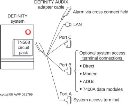
Figure

+7


Related documents
