Iot Based Smart Battery Station Using Wireless
Power Transfer Technology
T Vijay Muni, A Satya Pranav, A Amara Srinivas
Abstract: IoT technology has been playing an increasingly important role in the development of modern technology. The idea of ―smart d evices‖, which are able to regulate and maintain themselves as well as respond to external stimuli has led to the new paradigm in appliance manufacturing, of which the household appliance and the electrical industries are the most affected. Also, on a side note, there have been many strides in wireless power transfer technology, some of which are great improvements in efficiency and reduction in size, which bring the technology closer to household applications. This project effectively aims to utilize the c onjunction of the two aforementioned technologies to create a prototype of a smart appliance, a battery charging station powered wirelessly and integrated with IoT technology, which enable the user to continuously monitor the critical parameters of the battery, such as charge level, input and output current, etc,. The logged data can also be accessed from anywhere, such as a sma rtphone or a PC, due to it’s easy availability as it is uploaded to the cloud. Thus, this project synthesizes a new generation of electronic devices, as demonstrated by the above discussed prototype
Index Terms: IoT, WPT, Inverter, Cloud, appliance, prototype
—————————— ——————————
1 INTRODUCTION
Smart devices are the new generation of devices whose primary characteristic is that they are capable of networking among themselves and with outside agents such as PCs, Smartphones, etc., utilizing an array of wireless communi-cation protocols like Bluetooth, Zigbee, NFC, Wi-Fi, LiFi, 3G, etc. The word ―smart‖ may also refer to a device that exhibits certain computing properties, like artificial intelli-gence, though not always. Smart devices can be designed to support a number ofenvironments, a range of various computing properties, and be used in three major areas: physical world, human-centered environments, and distrib-uted computing environments.Usually, smart devices con-sist of a hardware layer (including a radio transmitting sig-nals), a network layer (through which devices communicate with each other), and an application layer (through which end users receive commands).Smartphones, tablets, pha-blets, smartwatches, smart glasses, and other personal electronics are some of the most commonly used smart devices.
Fig 1. A collection of smart devices
1.1 IoT Technology:
IoT refers to the Internet of Things, which are a series of interrelated computing devices, mechanical or virtual com-puters, artifacts, animals and individuals with unique identi-fiers (UIDs) and the ability to transfer information over a network without the need for human or human-to-computer communication. IoT devices can be either used as standalone devices or can be added as upgrades to al-ready existing devices. The modularity of IoT provides a lot of advantages and can be utilized effectively to bolster the capabilities of already existing devices, making it a powerful tool in the arsenal. Coupled with cloud storage platforms, IoT devices can be used to monitor and log data from re-mote devices such as sensors, factory instruments, etc.
Fig 2: Several IoT Protocols
1.2 Motivation
As stated, the aim of the project is to fabricate a prototype of a smart device, by a combination of three major technol-ogies: IoT, Smart Devices and Wireless Power Transfer. By a combination of the above three technologies, taking their benefits, an electrical device capable of continuous data logging and monitoring can be achieved. By improving on the design on a conventional battery charger, a prototype which can lead to further developments is achieved, and if feasible, used commercially. This project documents the integration of IoT technology with electrical devices, it’s fea-sibility and results, thus adding the scope to improve al-ready existing designs of electric devices, as upgrades.
2
WIRELESS
POWER
TRANSFER
Wireless power transmission (WPT), wireless power trans-mission, wireless power transmission (WET) or
electro-_________________________________
• T Vijay Muni, Department of Electrical and Electronics, Koneru Lakshmaiah Education Foundation, Vaddeswaram, A.P, India
• A Satya Pranav, Department of Electrical and Electronics, Koneru Lak-shmaiah Education Foundation, Vaddeswaram, A.P, India
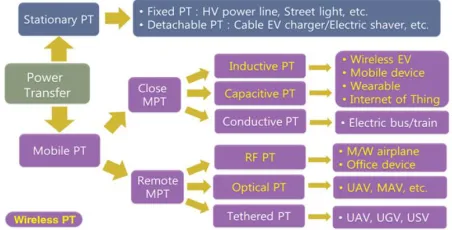
magnetic power transmission is the transfer of electrical energy without wires as a physical connection.Wireless power methods fell primarily into two groups, close field and far-field.For near-field or non-radiative methods, energy is transmitted over short distances through magnetic fields by means of inductive couplings between wire coils or electri-cal fields by means of capacitive couplings between metal electrodes.In far-field and radiative methods, also known as energy beaming, power is distributed through electromag-netic radiation signals, such as microwaves[7 ] and laser beams. Such techniques can transport energy longer dis-tances, but they must be guided at the receiver.
3: A general classification of power transfer in terms of mobility, distance, and means of poweing.
Remote power is one of the new expressions portraying this century. The need for wi-fi power transmission (WPT) is developing quickly in the time of mobility.The query inspira-tions and its relative noteworthiness are related to constant applications. Convenientce is the key inspiration for wi-fi control move as the quantity of versatile units is immensely expanding and wired chargers will limitation their conveya-bility. Electric autos and cell robots broad spreading is clung to the accessibility of remote battery chargers since versatil-ity is their dominating concern.
Some of the major benefits of WPT are:
Allows multiple batteries to be charged simultaneously. This is done by adjusting the geometry of the coil as well as by providing broad loading surface areas, such as table tops or charging benches.
Wireless power transfer allows for greater spatial inde-pendence between the power source and the device to be charged. The two do not have to be exactly matched for the transfer of power.
The technology is safe and used in remote controls, mobile headset alarms, portable thermostats, smoke detectors, smartphone devices, notebooks, etc.
Some disadvantages are:
Relatively low efficiency as compared to conventional power transmission systems, but new advances have been steadily improving the transfer efficiency.
Requires a bit of setup before functional.
They are usually operated at a very high frequency, thus making them unfavorable for some cases.
Fig 4: A brief overview of a topology for wireless power transfer
2.1 WPT by mutual inductance:
Through inductive coupling (electromagnetic induction and inductive energy transfer) the power is passed to the mag-netic field between the wire coils.The transmitter and the receiver coils create a transformer together. The alternating current (AC) through the transmitter coil produces an oscil-lating magnetic field according to the law of Ampere. The magnetic field travels through the transmitting wire, where the opposing EMF (voltage) is caused by Faraday's princi-ple of induction, which induces an alternating current in the transmitter.
Fig 5: An illustration of IPT
around the flip of the twentieth century, however the ad-vantages of the utilization of thunderous coupling to make greater transmitting separation have exclusively as of late been discussed.Every full circuit comprises of a wire curl associated with a capacitor or a self-thunderous loop or distinctive internal capacitance resonator. Both of them are intended to answer at the indistinguishable resounding re-currence. The reverberation between the loops will appar-ently grow the holding and the exchange of pow-er.Resonant building is now normally did into regular induc-tive remote quality frameworks. One of the probabilities visualized for this development is the remote power appro-priation locale. A loop in the divider or roof of a space could allow wi-fi vitality to lights or cell phones some place in the live with perfect yield.
2.2 Mathematical model of IPT Circuit:
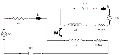
Fig 6: An equivalent circuit model for series-series inductive power transfer
The above figure describes the mathematical model of the wireless power transfer system using the inductive coupling approach. Fig.2.5 displays the simpler corresponding circuit design of the wireless power transmission system with two resonant coils in sequence. Load energy is enhanced by increasing the frequency and inductance of each other or by increasing the strength of the source present.The loop equations of the above circuit are:
Then, there's the distribution voltage. The moving currents in the primary and secondary coils are the corresponding impedances of the transmitting and receiving loops, respec-tively. M is the reciprocal coupling between the two coils which relies on the factor of coupling between the coils and the selfinductancedepends on the coupling and the induct-ances L1 and L2.
The corresponding impedances Z1 and Z2 can be general-ized and approximated at the resonance frequency.
Where R1acand R2ac are the series resistances of the pri-mary and secondary coils, respectively. and are the source and load resistances, respectively. The resonant frequency ω is defined as
The load power can be calculated using
The power transfer efficiency is given by
From equations (7) and (8), the load power increases by increasing the frequency or inductance of each other or by increasing the magnitude of the source current. From for-mula (8), output improves by reducing parasitic resistance, rising frequency and increasing inductance.The power bonding theory describes how electrical energy is moved from one system to another. When the contact between the couplers is induced by the magnetic field of one of the cou-plers, the coupling is defined as a magnetic coupling. The more stream the receiver reaches; the stronger the coils are combined. The degree of coupling is represented by the parameters of coupling. From formula (3), it is obvious that the coefficient of coupling k depends on the medium be-tween the two coupled coils and their parameters, such as the number of twists, the cross-section region and the width of the coils.
3 CIRCUIT
DIAGRAM
ASSEMBLY
The design of the power supplies of the Tx and the Rx side are explored, as well as the assembly and the working of the prototype. On the Tx side, the supply is first stepped down to 24V using a transformer and rectified using a full bridge rectifier to a voltage of 36V, which is further reduced to a voltage of 15V and 5V via a regulator to supply the ATMEGA328P microcontroller. The coils are fed with the 38V unregulated line which is inverted using a fast switch-ing switch, based on a class E configuration.
The circuit diagram of the Tx side is as below:
The circuit diagram of the Rx side is as below:
4 RESULTS
AND
DISCUSSION
The Tx side of the project after assembled is shown below:
Fig 8: Tx side of final assembly
As we can observe in the above image, the Tx side of the project consists of a Class-E configured switch connected to an Aluminium heat sink, as the switching losses are high and the temperature of operation is increased. The efficien-cy of the entire process is about ~50-65%, which is not very high but since this is a prototype setup the energy losses can be ignored. Another problem we have faced during as-sembly is the design of power supply for the pro-ject(completed power supply design is provided in the Tx circuit diagram above) as it was hard to design a constant 5V power supply from 36V DC.
Rx side of the final assembly:
Fig 9: Rx side of the assembly
On the Rx side, the 12V transformer powers the electronics board which contains the Arduino Nano and the ESP 8266, along with an LCD to indicate the battery Rate of Charge(RoC). The problems faced during the assembly of the Rx side is the orientation of the coils along with the power supply for ESP8266 as it takes 3.6V as an input.
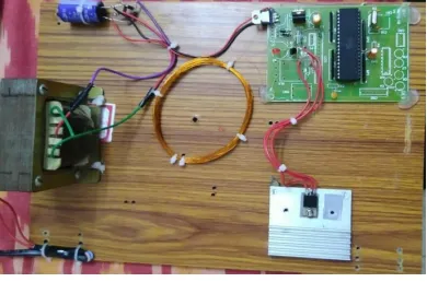
Fig 10: Finished Prototype
The above protoype is compact and small, requires only a few components to charge the battery and upload the data to the cloud via the ESP8266 Module. The battery charge status can be monitored anytime from the cloud. Here is the data, as seen on an android phone:
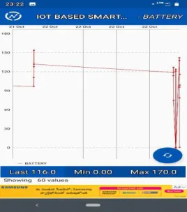
Fig 11: Monitoring of Data using Thingspeak module
As we can see in the above image, the battery charging data can be accessed from anywhere via the thingspeak network. This provides us with the advantage that the work-ing of the charger and the chargwork-ing status can be monitored in real time, and the controller can be programmed to send out alerts to the user in case of completion of charge.
5
CONCLUSION
In conclusion, this prototype provides the framework for an IoT integrated smart electronic device, a device which will pave the way for future approaches to smart electronic de-vices that can be integrated into networks, thus enabling better monitoring and control. The use of Wireless Power Transfer to transfer the power in a compact circuit also shows that by some improvements in the WPT tech, the devices of the future might me more compact and secure and operate at a higher efficiency. WPT provides isolation to the circuit and protects the transmission and receiving sides from disturbances in the other side, and WPT can be used for applications like dynamic battery charging and mass charging stations which will prove to be a boon for the implementation of Electrical Vehicle technology in the fu-ture.
6
REFERENCES
[1] Samanta, S., & Rathore, A. K. (2016). Wireless
power transfer technology using full-bridge current-fed topology for medium power applications. IET Power Electronics, 9(9), 1903– 1913.doi:10.1049/iet-pel.2015.0775
[2] Kurs, A., Karalis, A., Moffatt, R., Joannopoulos, J. D., Fisher, P., &Soljacic, M. (2007). Wireless Pow-er TransfPow-er via Strongly Coupled Magnetic Reso-nances. Science, 317(5834), 83– 86.doi:10.1126/science.1143254
[3] Zhang, Z., Pang, H., Georgiadis, A., &Cecati, C. (2018). Wireless Power Transfer - An Overview. IEEE Transactions on Industrial Electronics, 1– 1. doi:10.1109/tie.2018.2835378
[4] Kumar, N., Sundaram, K. M., &Anusuya. (2017). IoT Based Smart Charger. Proceedings of the International Conference on Big Data and In-ternet of Thing - BDI-OT2017.doi:10.1145/3175684.3175685
[5] Kim, J., Kim, J., Kong, S., Kim, H., Suh, I.-S., Suh, N. P., … Ahn, S. (2013). Coil Design and Shielding Methods for a Magnetic Resonant Wireless Power Transfer System. Proceedings of the IEEE, 101(6), 1332–1342.doi:10.1109/jproc.2013.2247551 [6] D. Ravi Kishore and T. Vijay Muni, ―Efficient energy
management control strategy by model predictive control for standalone dc micro grids‖, AIP Confer-ence Proceedings 1992, 030012 (2018); doi: 10.1063/1.5047963
[7] Kumar, M.K. Datta, D.V. T Vijay Muni., Perfor-mance enhancement of asynchronous machine with super Capacitor, International Journal of Engi-neering and Advanced Technology, 8(4), pp. 1208-1210.
[8] Ramakrishna, B., Srikanth, T., Chaitanya, M.N., Muni, T.V., ―Comparative analysis of perturb and observe method and current based method‖, International Journal of Innovative Technology and Exploring Engineering 8(6), pp. 1012-1016.
[9] Sowmya, S., Sai Sri Vasthava, V.K., T Vijay Muni, ―Active filter control strategies for renewable power generation systems using ANN controller‖, Interna-tional Journal of Innovative Technology and Explor-ing EngineerExplor-ing 8(5), pp. 690-696.
[10]Harshith, I., Raj, B.P., Raja Sekhar, G.G., T Vijay Muni, ―A novel methodology for single phase trans-formerless inverter with leakage current elimination for pv systems application‖, International Journal of Innovative Technology and Exploring Engineering, 8(6), pp. 1017-1021.
[11]Sudharshan Reddy, K., Sai Priyanka, A., Dusarlapudi, K., T Vijay Muni, ―Fuzzy logic based iUPQC for grid voltage regulation at critical load bus‖, International Journal of Innovative Tech-nology and Exploring Engineering, 8(5), pp. 721-725
[12]Swapna Sai, P., Rajasekhar, G.G., T Vijay Mu-ni, Sai Chand, M., ―Power quality and custom pow-er improvement using UPQC‖, Intpow-ernational Journal of Engineering and Technology(UAE) 7(2), pp. 41-43.