Indoor Topology Navigation System for Robotic
Control
Alagurani G Suresh Kumar. R
PG Student Assistant Professor
Department of Electrical & Electronics Engineering Department of Electrical & Electronics Engineering Kumaraguru College of Technology, Coimbatore, India Kumaraguru College of Technology, Coimbatore, India
Abstract
The aim of this project is to develop and implement a line following module and RFID technology on a Robot for the task of warehouse management. A GSM module is also interfaced, for the delivery of the goods will notify the user with a text message to the registered mobile number. The tags on items are scanned using RFID technology and it is placed in their specified location via line follower Robot. This project is an integration of RFID and line following Robot. RFID is a boon as it can store and retrieve data infra-red sensors administer its movement and line following. The storing and retrieval of Data is done with the help of RFID tags and Transponders. GSM module is used to notify the user with a text message to the registered mobile number on delivery of goods.
Keywords: Line Follower Robot, UART, GEAR Motor, RFID Tag
________________________________________________________________________________________________________
I. INTRODUCTION
A Collection of data is the core job of an RFID system. The use of tags and transponders in it help acquire the purpose of data storage and repossession. Tags, Readers, Antenna and Software span the four salient parts of an RFID system. This grouping of a Robot and RFID will transport a significant key to warehouse administration. Using this RFID robot the purpose of classify and allocating goods in a warehouse will be served.
The following the scopes of this RFID robot.
1) Controller board, motor driver and RFID for reader module are included in the circuit design. 2) Microcontroller programming achieves the software expansion of the Robot.
3) Establishment of goods and their locations is done by RFID tags.
II. PLATFORM SETUP
Mobile Vehicle
The line find concept is verified on mobile robot. The vehicle implements differential drive approach using DC motors, their quickness controlled by arudino controller.
Infra-Red Sensor
A reflective photoelectric sensor repose of a standard infra-red LED and a photoelectric transistor has been suited in the vehicle. Infra-red sensor production current at the output which is proportional to the amount of light it receives.
Software Setup
Since the mobile vehicle to work seductively for line tracking in a smooth manner the software program is must need. As for choosing the programming language a lot of options are applicable, but we prefer C for it’s universalize The controlling software for the testing has been developed using C sharp.
RFID
It’s a system for save and remotely retrieving data using wireless technology operating with 50 KHz to 2.5 GHz. It comprises of 3 basic elements: RFID tag, recruiter and a host line of business system. Data encoded on the tag contains a different of information about the object including item description through EPC.
III. METHODOLOGY
robot and communicate with the RFID reader. Due to the singularity of RFID tag, the moving is controlled by commands such as turn left, turn right, speed up and speed down etc. The mobile robot can read the moving force commands from the tag and accomplish the proper actions. The novel localization system for a mobile robot is proposed to recover the efficiency of the system.
Electronic Design
The components that are need for the electronic circuit design includes an LED, potentiometers, Phototransistor pairs, resistors, RFID Tag and Reader, DC Geared motors, Motor Driver IC’s and a microcontroller. The microcontroller used here is arudino, Either L293D or ULN 2003 IC can be used as motor driver because ULN2003 requires relays to provide supply to the motors.
Light emitter: emitter is on the input side and takes the incoming signal and converts it into a light signal. Typically light emitting diode is recycled as the light emitter.
Light detector: Light detector detects the light against the emitter and converts it into an electrical signal. The light detector can be a phototransistor.
Indoor Positioning System
The easy way to describe Indoor Positioning Systems (IPS) it’s like a GPS for indoor environments. IPS can be used to locate people or objects inside buildings, typically via a mobile device such as a smart phone or tablet. IPS relies on technology like wall- or ceiling-mounted beacons that work together in detecting a user’s or object’s location, deriving an exceptionally correct position. Like GPS, IPS systems can then detect the commend in which the device is travelling, it can predict the user’s pathway based on that information so the positioning remains exact as the space is traversed.
Indoor positioning is in demand for a variety of uses:
The goal of indoor positioning for some users particularly hospitals and malls, is to provide navigation aid, others wish to use indoor positioning to better market to customers, provide just-in-time instruction via audio for tours, offer video or extend reality experience or joining people of interest in closeness to one another. The U.S. Federal Communications Commission optimism to use indoor positioning to provide timelier and more effective emergency services
LCD display
A liquid crystal display is special thin flat boards that can let light go through it, or can block the light. The panel is made upon of several blocks, and every block can be in any shape. Each block is full filled with liquid crystals that can be made clear or solid, in this place by changing the electric current to that block. Liquid crystal displays are repeatedly abbreviated LCD Liquid crystal displays are repeatedly used in battery-powered devices, such as digital watches, because they uses very little electricity.
DC motor
It is any of a class of revolving electrical machines that converts direct current electrical current into mechanical current. The most common types relay on the forces produced by magnetic fields. Nearly all types of DC motors have some constitutional mechanism, either electromechanical or electronic, to regularly change the direction of current flow in the part of motor. DC motors were the first type widely used, as they could be powered from existing direct-current lighting power distribution system. DC motor's speed can be controlled over a wide range, using either a different supply voltage or by changing the strength of current its field windings. Small DC motors are used in tools, toys, and appliances. The universal motor can be operate on direct current but it is a lightweight motor used for compact power tools and appliances. Larger DC motors are used in pressure of electric vehicles, elevator and up hold, or in drives for steel circuim mills. The advent of power electronics has made restoration of DC motors with AC motors possible in many applications.
Transmitter
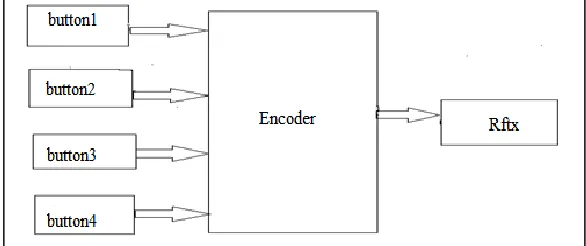
Transmission operation clean as the timing does not have to be determined from the line state, it bound on any fixed timing intervals. As soon as the sending system security a character in the shift register the UART generates a start bit, shifts the need number of data bits out to the line, generates and send the parity bit , and sends the stop bits. Considering full-duplex operation requires characters to be sent and received at the equivalent time, UARTs use two different shift registers for transmitted and received characters. In this place High performance UARTs could contain a transmit FIFO (first in first out) buffer is to allow a CPU or DMA controller to deposit multiple characters in a barrage into the FIFO rather than have to deposit one character at a time into the FIFO.
Receiver
These all operations of the UART hardware controlled by a clock signal which runs at a multiple of the data rate, typically 8 times the bit rate. The receiver tests the state of the incoming signal on every clock pulse, looking for the starting of the start bit. If the apparent beginning bit lasts at least one-half of the bit time, it is valid and signals the start of the new character. If not possible, it is considered a specious pulse and is ignored. After waiting a further bit time, the state of the line is again sampled and the resulting level clocked into a shift into register. After the required number of bit periods for the character dimension has elapsed, the content of the shift register are made usable to the receiving system. The UART will set a flag indicating new data is available, and may also generate to a processor interrupt to request that the host processor transfers the received data.
Fig. 2: Receiver block diagram
Features (GSM 900 module)
Dual-Band 900/ 1900 MHz
GPRS multi-slot class 10/8GPRS mobile station class B Compliant to GSM phase 2/2+Class 4 (2 W @850/ 900 MHz) Class 1 (1 W @ 1800/1900MHz)
Low power consumption
Linear Movement
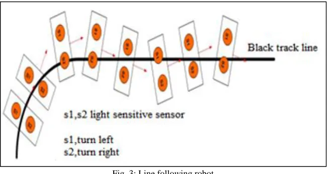
Fig. 3: Line following robot
A picture set-up for linear movement validation is the position consistent by the linear encoder is used as the ground truth by first taking the average of the measured position from in sence before the robot starts to move as the initial position. The output of the sensor to be fusion is then compared with the measured position of the robot from the encoder
Rotational Movement
Fig. 4: Rotational moving
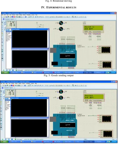
IV. EXPERIMENTAL RESULTS
Fig. 5: Goods sending output
V. CONCLUSION
An autonomous robot can be controlled by using wireless technology and this robot follows the line and moves to the desired location and performs pick and place operation of item. These type robots can be configured to perform various applications. However in the prototyping stage the robot may not be able to accomplish all its tasks successfully. The application of this robot has a good potential not only in warehouse management but also in libraries, supermarkets, offices, buildings etc. This robot will manage goods positively according to the database programmed in the robot. These Robots can be arranging in vital locations and can also be used in the military for rescue missions. These Autonomous fixed robots can communicate with adhoc network and can perform even better. If we develop the robot means will save cost and time and employ’s work.
REFERENCES
[1] Shirehjini, A. Massine, and S. Shirmohammadi, “An RFID-based position and orientation measurement system for mobile objects in intelligent
environments,” IEEE Transactions on Instrumentation and Measurement Jun. 2010..
[2] S. S. Saad and Z. S. Nakadv, “A standalone RFID indoor positioning system using passive tags,” IEEE Transaction on Industrial Electronics, Jul. 2010.
[3] A. Errington, B. Daku, and A. Prugger, “Initial position estimation using RFID tags: a least-squares approach,” IEEE Transactions on Instrumentation and
Measurement, Nov. 2010.
[4] J.-H. Wang and Y. Gao, “Land vehicle dynamics-aided inertial navigation,” IEEE Transactions on Aerospace and Electronic Systems, Oct. 2010.
[5] Mustafa Alani, Widad Ismail, and JS.Mandeep, Active RFID system and applications. Electronics World, 115(1877):22–24, 2009.
[6] Amit Kumar, M. Manjunata, A.K. Majumdar, J. Mukhopadayay and Rusha Patra, "An Electronic Travel Aid for Navigation of Visually Impaired Persons",
3'd International Conference on Communication Systems and Networks, pp.1-5, January 2011.
[7] Barroso J, Faria J, Fernandez H, Martins P, "Electronic White Cane for Blind People Navigation Assistance", World Automation congress,pp.l-7,September
2010.
[8] Oimitrios Oakopouslos and Nikolaos G.Bourbakis, "Wearable Obstacle Avoidance Electronic Travel Aids for Blind: A Survey", IEEE Transactions on Systems, Man and Cybernetics, Vo1.40, No.1, pp.25-35, January 2010.
[9] D. O. Sales, F. S. Osório e D. F. Wolf, “Topological Autonomous Navigation for Mobile Robots in Indoor Environments using ANN and FSM”. 1a
Conferência Brasileira de Sistemas Embarcados Críticos, São Carlos, 2011.
[10] OpenCV, Welcome - OpenCV Wiki. Available in http://opencv.willowgarage.com/wiki/, Accessed in Feb 2012.