Design, Analysis and Performance Investigation of
Heat Extraction Unit using Fins
Pragnesh D. Patel Uday V. Joshi
PG Student Professor
MGITER GEC, Surat
Abstract
Over the last years, there has been growing interest in applying new technologies to improve the heat transfer from the various heat sources such as geothermal energy, power plants, diesel engines, automobiles and other industrial heat-generating process. The heat transfer enhancement by means of extended surface type heat exchanger is well established technology and at present being adopted by most of the waste heat recovery system. Different types of heat transfer enhancement techniques using fins are available in extended surface type heat exchanger but each of this technique having different heat transfer enhancement ratio. Different researchers have analyzed the effect of fin geometry and combination of fins on heat transfer enhancement technique. In present research, find out the effect of fins on heat transfer augmentation or heat transfer coefficient for extracting heat from various waste heat sources.
Keywords: CFD, Numerical modeling, Heat transfer, Finned heat exchanger
_______________________________________________________________________________________________________ I. INTRODUCTION
Heat transfer can be defined as the one type of process through which energy transport takes place. It can be done when two physical bodies were at different temperatures than transfer of thermal energy is known as heat transfer and it is continuously until the thermal equilibrium takes place. Thus, heat is always spontaneously flows from a hot material to cold one. The basic principle of heat transfer obeys second law of thermodynamics.
Heat transfer in pipe flow is widely used in refrigeration, air conditioning, chemical, power and petrochemical industries etc. Different researchers used various types of augmentation technique to enhance the single phase convection heat transfer of pipe flow. A great number of researchers has been made on different types of pipe flow enhanced technique. Major results of enhancement study either numerical or experimental study types, are often expressed by friction increase ratio and heat transfer enhancement ratio. The enhancement techniques are classified into passive and active methods.
It is a well-known fact that with the emerging worldwide crisis energy shortage is a major problem. So energy saving is our major purpose of heat transfer enhancement study and whenever we have using any enhancement technique will introduce additional pressure drop. To overcome that pressure drop we needs to extra pumping power. Therefore whenever we have using this technique, we needs to very careful about pressure drop.
There are three methods are used for augmentation of heat transfer.
1) Active method: In this method some external power input is enhancement /augmentation of heat transfer. For example, mechanical aids, surface vibration, electrostatic field, fluid vibration, etc. requires an external power to enhancing heat transfer.
2) Passive method: For enhancing the heat transfer, in this method use of surface or geometrical modification are required. For example, insert extra component, extended surface, rough surfaces, swirl flow device, coiled tubes, surface tension device etc. and also additives for fluids requires to enhancing heat transfer.
3) Compound method: For enhancing the heat transfer, in this method combination of above two methods is used. For example, twisted tape with wire coil, corrugated tube with twisted tape etc. to enhancing heat transfer. The passive and combination method does not need any external power input for enhancing heat transfer rate.
Advantages of using those Techniques
Design, Analysis and Performance Investigation of Heat Extraction Unit using Fins
(J4R/ Volume 02 / Issue 03 / 004)
waste heat recovery technologies in india were thermoelectric generation, organic Rankine cycle, six stroke engines, turbo-charging, exhaust gas recirculation, different types of engine heat exchangers. In this paper they have short review about different technologies used by researchers. So finally they have concluded that the using of fin was more applicable than foams and porous materials.
2) M. Hatami et al. studied, “Numerical study of finned type heat exchangers for ICEs exhaust waste heat recovery” in 2015 and modeled numerically the two types of heat exchangers which were used by recover the exhaust waste heat also they have tried to find out the best viscous model. They were concluded that the RNG k-e model was best and Recovered heat can be improved by increased fin length and fin numbers where maximum heat recovery occurs as high engine loads and speed. They were studied the effects of sizes and numbers of fins on recovered heat at various engine loads and speeds also. 3) M. Hatami et al. studied, “Optimization of finned-tube heat exchangers for diesel exhaust waste heat recovery using CFD
and CCD techniques” in 2015 and optimized finned tube heat exchanger using response surface methodology and central composite design (CCD). Based on CCD principle taking 15 HEX cases with different fins height, thickness and number were modeled numerically. They were concluded that the height of fin was negative effect on pressure drop and thickness of fin was positive effect on heat recovery. According to CCD technique, they generate best optimized case and created desirability graph for optimized case in which desirability, fin thickness and fin heights were 0.826, 39.27 and 4.
III. METHODOLOGY OF WORK
Numerical Methodology of a Heat Extraction Unit
The commercial code ANSYS 15.0 is adopted to simulation of flow and heat transfer in a heat extraction unit. The numerical simulation is performing with a three dimensional steady state turbulent flow system. To solve the problem, governing equations for the flow and heat transfer are modified according to the conditions of the simulation set up. Because the problem is assumed to be steady state, the time dependent properties are dropped out from the governing equations.
Governing Equation
The resulting equations are:
Continuity equation can be expressed as:
∂ ∂xi
(ρui) = 0
Momentum equations can be expressed as: ∂ ∂xi
(ρuiuk) = ∂ ∂xi
(μ∂uk ∂xi
) − ∂p ∂xk Energy equation can be expressed as:
∂ ∂xi
(ρuit) = ∂ ∂xi
(k Cp
∂t ∂xi
)
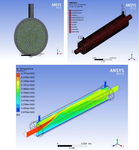
Fig. 1: Steps ( design, mesh, boundary condition and solution) of the numerical modeling for heat exctraction unit in ANSYS 15.0.
Transport equations for RNG k𝜀 model in general form are: Turbulent kinetic energy:
∂ ∂x(ρk) −
∂ ∂xi
(ρkui) = ∂ ∂xj
(αkμeff ∂k ∂xj
) + Gk+ ρε
And turbulent energy dissipation:
Design, Analysis and Performance Investigation of Heat Extraction Unit using Fins
(J4R/ Volume 02 / Issue 03 / 004)
The empirical constants for the RNG k-e model are expressed as:
Cμ= 0.0845 , C1ε= 1.42 , C2ε= 1.68 , β = 0.012 , ἡ0= 4.38 , αk= αε= 1.39.
The heat transfer rate when hot fluid is passing through the inner side of the tube or heat rejected by the by the hot fluid can be expressed as,
Qh = ṁhcp,h(Th,1− Th,2)
Where 𝑚̇ℎ is the mass flow rate of the hot fluid, 𝑐𝑝,ℎis the specific heat of the hot fluid and Th,1 and Th,2 are the inlet and outlet
temperatures of hot fluids.
Same the heat transfer rate or heat gained by the cold fluid for outer side can be expressed as, Qc = ṁccp,c(Tc,2− Tc,1)
Where 𝑚̇𝑐 is the mass flow rate of the cold fluid, 𝑐𝑝,𝑐is the specific heat of the cold fluid and Tc,2 and Tc,1 are the outlet and inlet
temperatures of cold fluids
The average heat transfer rate can be calculated by taking average heat transfer rate of hot and cold fluid, Qavg=
Qw+ Qc 2 Qavg is an average heat flux of heat extraction unit.
Table – 1
Temperature-dependent properties of exhaust gases
Exhaust gas properties 𝑨 + 𝑩 × 𝑻 + 𝑪 × 𝑻𝟐+ 𝑫 × 𝑻𝟑
A B C D
𝝆 (kg/m3) 2.5040122e+00 -5.958486188e−03 5.578942358e−06 −1.772600e−09
Cp(J/kg K) 1.0155809e+03 −1.512248401e−01 4.544870294e−04 −1.785063e−07
𝝁 (kg/m s) 1.3251869e−06 6.7400613700e−08 −3.74904357e−11 1.1100749e−14
k (W/m K) −3.182421e−03 1.1858478256e−04 −7.70600423e−08 2.9396539e−11
Table - 2
Thermal properties of fins and coolants materials
𝝆 (kg/m3) Cp(J/kgk) 𝝁 (kg/ms) k (W/mk) Water 998.2 4182 0.001003 0.6 Carbon steel 7858 486 - 52
Geometry, Mesh generation and Boundary condition
In the modeling of heat extraction unit, lengths of HEU are 70 cm with 12 cm inner diameter and 14 cm outer diameter while the gas inlet and outlet diameters are considered 48 mm as shown in Fig. 1. Both inlet and outlet of the water pass are placed in the upper surface of the HEX with a 2 cm diameter. Also the dimensions of fin are 39.27 cm length and 4 cm width. As described before 15 cases of HEXs are modeled and their properties are presented in Table 1. The HEXs are considered well-insulated; hence, the heat losses to the environment are totally neglected. As an approximation, the properties of air can be used for diesel exhaust gas.
Due to high temperature in exhaust, temperature dependent properties are considered for exhaust gases and for each property, a fourth order polynomial is plotted and its equation and coefficients are shown in Table 1. Also, all the solid phases (fins and walls) are made from carbon steel with 3 mm thicknesses and water is the coolant and their properties are presented in Table 2. The 3D grid system was established using the ANSYS 15.0 commercial software. In HEU, three separate domains or volumes should be considered for gases, solid and liquid phases. In this grid systems with approximately 700,000 cells are adopted for calculation of the whole heat extraction unit.
As described before, the commercial code ANSYS 15.0 is adopted to simulate the flow and heat transfer in the computational domain. As reported by Patankar [5], the governing equations are discretized by the finite volume method [4]. The QUICK scheme is used to discretize the convective terms and the SIMPLE algorithm is used to deal with the coupling between velocity and pressure.
IV. RESULT AND DISCUSSION
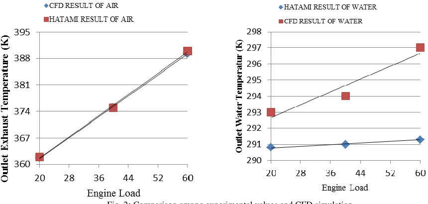
Fig. 2: Comparison among experimental values and CFD simulation
As seen in these figures, numerical and experimental outcomes are in good agreement which is confirmed by Fig. 4.4 through percentage of the error for these parameters. The parameters considered are exhaust outlet temperature, water outlet temperature. As seen, accuracy of numerical solution for both the exhaust and water outlet temperatures is about 5% which are acceptable due to assumptions in the numerical solution or CFD simulation.
V. CONCLUSION
In this study, after this validation, average recovered heat is calculated and it should be cleared that the HEU has greater heat recovery performance due to its more surface area of fins for heat transfer. Furthermore, maximum heat recovery is occurred in the full load due to higher exhaust temperature in this engine operating condition compared to lowering one. It is evident that in all situations recovered heat increases by increasing the engine load due to higher exhaust temperature which enhance the exhaust heat recovery.
NOMENCLATURE
A Cross sectional area of heat extraction unit, m2
Ai Inside area of heat extraction unit, m2
Ao Outside area of heat extraction unit, m2
Cp,c Specific heat of cold fluid, kJ/kg.k
Cp,h Specific heat of hot fluid, kJ/kg.k
Di Inside Diameter, m
Do Outside diameter, m
h Heat transfer coefficient, w/m2.k
hi Inside heat transfer coefficient, w/m2.k
ho Outside heat transfer coefficient, w/m2.k
k Thermal conductivity of the material, w/m.k
L Tube length, m
𝑚̇ Mass flow rate of fluid, kg/s 𝑚̇𝑐 Mass flow rate of cold fluid 𝑚̇ℎ Mass flow rate of hot fluid
Nu Nusselt number
Q Amount of heat flux, w
q Heat flux, w/m2
T Temperature, °C
Tc Temperature of cold fluid, °C
Design, Analysis and Performance Investigation of Heat Extraction Unit using Fins
(J4R/ Volume 02 / Issue 03 / 004)
Greek symbols
𝜌 density ,kg/m3 𝑣 Kinematic Viscosity, m2/s μ Dynamic viscosity, pa/s
∝ Helix angle
𝜃 Rib included angle 𝛿 Wall thickness 𝜂 Overall enhancement ratio
Abbreviations
HTC Heat transfer coefficient HEU Heat Extraction Unit WHR Waste heat recovery
Subscripts
c Cold fluid h Hot fluid i Inside o Outside
REFERENCES
[1] M.Hatami et al., “A review of different heat exchangers designs for increasing the diesel exhaust waste heat recovery”, Renewable and Sustainable Energy Reviews 37(2014)168–181.
[2] M. Hatami et al., “Numerical study of finned type heat exchangers for ICEs exhaust waste heat recovery”, Case Studies in Thermal Engineering 4 (2014) 53–64.
[3] M. Hatami et al., “Optimization of finned-tube heat exchangers for diesel exhaust waste heat recovery using CFD and CCD techniques”, International Communications in Heat and Mass Transfer 57 (2014) 254–263.
[4] Vamsi Mokkapati, Chuen-Sen Lin, Numerical study of an exhaust heat recovery system using corrugated tube heat exchanger with twisted tape inserts, Int. Commun. Heat Mass Transfer (2014), http://dx.doi.org/10.1016/j.icheatmasstransfer.2014.07. 002.
[5] V. Pandiyarajan, M. Chinna Pandian, E. Malan, R. Velraj, R.V. Seeniraj, Experimental investigation on heat recovery from diesel engine exhaust using finned shell and tube heat exchanger and thermal storage system, Appl. Energy 88 (2011) 77–87.
[6] M. Hasanuzzaman, N.A. Rahim, R. Saidur, S.N. Kazi, Energy savings and emissions reductions for rewinding and replacement of industrial motor, Energy 36 (1) (2011) 233–240.
[7] M. Ghazikhani, M. Hatami, D.D. Ganji, M. Gorji-Bandpy, Gh. Shahi, A. Behravan, Exergy recovery from the exhaust cooling in a DI diesel engine for BSFC reduction purposes, Energy 65 (2014) 44–51.