RESEARCH ARTICLE
Approach function study
for concierge-type robot by model-based
development with user model
for human-centred design
Yoshinobu Akimoto
*, Eri Sato‑Shimokawara, Yasunari Fujimoto and Toru Yamaguchi
Abstract
Service robots are common sights in everyday life. The service robots are expected to provide useful services with a high degree of usability, and a high degree of user experience (UX) to users and other persons around the service robots. In addition, the human‑centred design (HCD) is being used in various industries, and HCD can be used also in the service robot industry for improving usability and UX. We have been researching a model‑based development with user model (MBD/UM) as a practical HCD process for service robots. Here, we studied an approach function on a concierge‑type robot that should have a high degree of usability and a high degree of UX from users’ viewpoint, by applying MBD/UM for HCD. The result of our study shows that MBD/UM can be a practical HCD process for develop‑ ing service robots.
Keywords: Service robot, Human‑centred design, Model‑based systems engineering, Model‑based development, User model
© 2016 The Author(s). This article is distributed under the terms of the Creative Commons Attribution 4.0 International License (http://creativecommons.org/licenses/by/4.0/), which permits unrestricted use, distribution, and reproduction in any medium, provided you give appropriate credit to the original author(s) and the source, provide a link to the Creative Commons license, and indicate if changes were made.
Background
Service robots are becoming more common in everyday life. The service robots are expected to provide useful ser-vices with a high degree of usability and a high degree of user experience (UX) from users’ viewpoint. We surveyed required functions on concierge-type robots, and found that an approach function was important for the robots because the robots had to approach users before talking with the users. Therefore, we studied the approach func-tion with a high degree of usability and a high degree of UX, by applying a development method which we named the model-based development with user model (MBD/ UM) [1] as a practical process of human-centred design (HCD) [2].
Current development process and MBD/UM for HCD Embedded-system products are expected to have a high degree of usability and a high degree of UX to satisfy user requirements. But, the products sometimes failed to satisfy the user requirements, because the products were designed on the basis of ideas and proprietary tech-nologies of individual manufacturers. Therefore, HCD becomes a popular way to satisfy user requirements.
We have been studying MBD/UM as a practical HCD process for service robots, especially those at risk of injuring stakeholders, i.e., users and other persons in the environment.
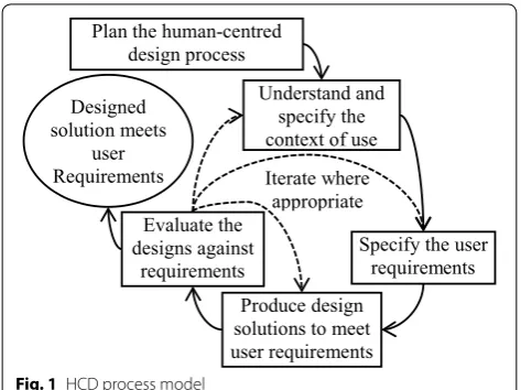
Figure 1 shows HCD process model taken from ISO 9241-210:2010.
Problems of current development process
Design solutions were evaluated by product samples and stakeholders. Therefore, long time and large cost were required to produce hardware of the product sam-ples, and there were risks to injure the stakeholders at evaluation.
Open Access
*Correspondence: akimoto‑[email protected]
And products were produced from the manufactures’ viewpoints, and then sometimes failed to satisfy user requirements. Therefore, HCD using paper prototyping [3] and mock-up [4] became popular. However the paper prototyping and the mock-up were not suitable for evalu-ating products which had various movements, because only limited movements of product could be imple-mented by the paper prototyping and the mock-up.
And there were some researches evaluating design solutions with a digital mock-up of product and a user model (UM) on a simulation tool such as a 3D CAD. The representative researches were “Virtual User Modeling and Simulation” (VUMS) [5] by VERITAS Project—FP7 IP [6] in EU, and “Digital Human” [7] by National Insti-tute of Advanced Industrial Science and Technology [8] in Japan. These method of evaluating the design solution by digital mock-up and UM were suitable for evaluating the products with simple functions controlled by stake-holders, but were not suitable for evaluating the products requiring condition-dependent actions and/or real time reactions in response to various behaviors of stakehold-ers, because only limited functions of product and lim-ited behaviors of stakeholder could be implemented in the digital mock-up and UM.
And there were some researches regarding the model-based development (MBD) [9]. MBD was a development method to produce design solutions with a device model of product and to evaluate design solutions repeatedly with the device model by simulation, instead by using an actual product sample. However in MBD, user activi-ties were defined as part of device model or environment model; that is, UM was not implemented as an independ-ent model separating from the device model and environ-ment model. Therefore, only limited functions of product
could be evaluated by simulation, due to a lack of UM which could simulate various behaviors of stakeholders.
Aim and approach
The aim of this study was to complete an approach func-tion which would satisfy the user requirements on a con-cierge-type robot, by applying MBD/UM as a practical HCD process with advantages as follows:
• To reduce time and cost required to produce the hardware of the product sample at evaluation.
• To evaluate the product by simulation, under various conditions and also repeatedly under the same condi-tion.
• To eliminate risks injuring test participants in the evaluation, and to reduce the risks in the certifica-tion.
We studied the approach function by MBD/UM con-sisting of Persona [10], model-based systems engineering (MBSE) [11], MBD and RT middleware (RTM) [12] as an MBD tool. RTM was a modular-based middleware with an ability of model-based simulation (MBS) which could replace the individual modules. We implemented MBD/ UM as a practical HCD process as follows:
• Understand and specify the context of use by Per-sona. Persona can describe both a profile of a stake-holder and a context of use of a product. Therefore, Persona can be effective to understand and to specify the context of use.
• Specify the user requirements by MBSE. MBSE can define user requirements for a product, and models of product and stakeholder as diagrams, drawn based on the profile of stakeholder and the context of use. Therefore, MBSE can be effective to specify the user requirements and the models of product and stake-holder.
• Produce design solutions to meet user requirements for MBS on RTM. MBD can produce design solu-tions for MBS with a device model of product and UM of stakeholder by using RTM, based on the user requirements and the models. Therefore, MBD can be effective to produce design solutions to meet user requirements.
• Evaluate the designs against requirements by MBS on RTM. MBD can evaluate the design solutions against the user requirements by MBS with the device model and UM on RTM. Therefore, MBS on RTM by MBD can be effective to evaluate the designs against requirements.
Plan the human-centred design process
Understand and specify the context of use
Specify the user requirements Produce design
solutions to meet user requirements Evaluate the
designs against requirements Designed
solution meets user
Requirements Iterate where appropriate
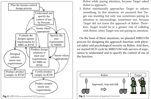
We added 2 steps to HCD process model as follows:
• Produce product sample on RTM. A product sam-ple can be produced on RTM by replacing the device model and UM with actual subsystems with hard-ware.
• Certify the product sample on RTM. The product sample can be physically certified safely by test par-ticipants on RTM.
Figure 2 shows MBD/UM as a practical HCD process.
Object robot and function
We surveyed the required functions on a concierge-type robot, hereafter referred to as Robot, providing services in an indoor hallway, and then, found that Robot should at least have an approach function, an emergency brak-ing function and a follow function, in addition to a basic function talking with a user, hereafter referred to as Tar-get, around Robot.
Among the required functions, we focused on the approach function, because Robot had to approach Tar-get before talking with TarTar-get, and Robot had some risks to injure Target or to give Target fears during approaching.
For studying the approach function on Robot from users’ viewpoints, we applied MBD/UM as a practical HCD process for implementing a high degree of usability and a high degree of UX to satisfy the user requirements.
Figure 3 shows the environment of the approach function.
Methods
We studied the approach function on Robot with physi-cal safety as the usability and psychologiphysi-cal security as UX, in accordance with MBD/UM as a practical HCD process. UM represents a typical user in individ-ual user groups, and can be a base of further study for personalization.
Plan the human‑centred design process
To start MBD/UM as a practical HCD process, we focused on the approach function in a wide hallway of a building such as a hospital, a shopping mall, or a nursing home.
And, to plan MBD/UM process, we surveyed situations in which the function was required, and then, we chose the situations as follows:
1. Target calls Robot for asking something. In this situa-tion, we assumed that Target waited for the arrival of Robot while paying attention, because Target asked Robot to approach.
2. Robot intentionally approaches Target to inform something. In this situation, we assumed that Tar-get was standing but only was sometimes paying its attention to surroundings, sometimes not, because Target did not know the approach of Robot. There-fore, Target would be at a greater risk of colliding with Robot, when Target was not paying its attention.
On the basis of these situations, we planned MBD/UM process for designing the approach function with physi-cal safety and psychologiphysi-cal security on Robot. And then, we started HCD cycle by MBD/UM with surveys of expe-rience to understand and to specify the context of use of the function.
Plan the human-centred design process
Understand and specify the context of use
by Persona
Specify the user requirements
by MBSE Produce design
solutions to meet user requirements
for MBS on RTM Evaluate the designs against requirements by MBS on RTM
Designed solution meets user requirements
Iterate where appropriate
Produce product
sample on RTM sample on RTMCertify product
Product sample meets user requirements
Iterate where appropriate
Fig. 2 MBD/UM as a practical HCD process
Robot Target
Approach, stop and talk
Understand and specify the context of use by Persona As the 1st step of MBD/UM as HCD cycle, the context of use has to be understood and specified for determining the user requirements. Therefore, we considered possible causes of collision between Target and Robot in a hall-way including light collisions without injury, and collision hazard by Robot.
We assumed that lack of attention was a cause of the collision or hazard between people in the hallway. So, we surveyed the causes of such inattention, and then chose mobile phone operation as a cause on the basis of our own experiences and the report [13] concluding that the mobile phone operation was a risky pedestrian behavior when crossing a street by distraction.
Then, to verify our assumption regarding the causes of collision or hazard, we clarified the situations in which persons collided with each other or pass such a hazard in a passage or hallway by administering a questionnaire to 9 respondents. The questionnaire asked the respondents if they had experienced any collisions or felt a collision hazard in passages or in the hallways, as follows:
• Have you experienced any collisions or felt a collision hazard with other people during walking?
• Have you experienced any collision or hazard with attentive people, inattentive people or both?
• What were the inattentive people doing at the experi-ence of the collision or hazard? Operating a mobile phone or others? If others, please describe what they were doing.
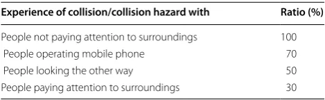
The result of the questionnaire showed that all respondents had had experiences of the collision or col-lision hazard with others. The result also showed that the inattentive people faced more risks of collision than attentive people, and the mobile phone operation was a cause of collision or hazard in the case of the inattentive people.
Table 1 shows the result of the question regarding the experience of collision or hazard.
The questionnaire asked the approach pattern when the respondent experienced the collision or hazard, as follows:
• Did the people approached at a constant velocity or by a deceleration, at the collision or the collision hazard?
The result to this question showed that the approach at constant velocity gave Target more fear of collision than the approach by deceleration.
Table 2 shows the result of question regarding the relation between the approach pattern and the fear of collision.
By these results, we defined a user profile of Target by Persona, and then, we assumed the context of use of Robot in the narrative of Persona, as follows:
• Target is standing sometimes attentive to its sur-roundings, sometimes inattentive, when Robot approaches.
• Target is inattentive during the mobile phone opera-tion.
• Target feels fear of collision, if Robot approaches at constant velocity and stops suddenly.
To the above, we added 4 assumptions on the basis of our own experience as follows:
• Target feels a fear of collision, if Robot approaches very close to Target.
• Target becomes attentive by being warned.
• Target feels a fear of collision, if Robot moves faster than Target.
• Inattentive Target may start walking suddenly.
Specify the user requirements by MBSE
As the 2nd step of MBD/UM as HCD cycle, the user requirements have to be determined on the basis of the specified context of use. Before clarifying the user requirements, a model of the stakeholder has to be spec-ified by drawing the diagrams in MBSE for understand-ing and definunderstand-ing the activities of stakeholder on the basis of the context of use. Then, using the model of stake-holder, the user requirements for the product can be determined by using the requirement diagram in MBSE. And, on the basis of the user requirements, a model of product can be defined by using the state machine dia-gram in MBSE.
Table 1 Experience of collision or hazard
Experience of collision/collision hazard with Ratio (%)
People not paying attention to surroundings 100
People operating mobile phone 70
People looking the other way 50
People paying attention to surroundings 30
Table 2 Approach pattern and fear of collision
Approach pattern with fear of collision Ratio (%)
Approach at constant velocity 90
Therefore, we first defined a model of Target by MBSE, for clarifying the user requirements for the approach function by Target.
Figure 4 shows the model of Target by a state machine diagram in MBSE.
In this study, we focused on the states of “Standing attentively”, “Standing inattentively” and “Monitoring environment”, because we assumed that Robot would move slower than Target and would not be able to catch walking Target.
Then, on the basis of the model of stakeholder, we specified user requirements for the approach function on Robot for standing Target, sometimes attentively, some-times inattentively by mobile phone operation, by using a requirement diagram in MBSE.
After that, we summarized the requirements as follows:
• The approach function has to warn an inattentive Target of Robot’s approach at an appropriate distance and to warn Target who may be starting to walk sud-denly, for ensuring psychological security.
• The approach function has to stop Robot at an appropriate distance to avoid a collision, for ensuring physical safety.
• The approach function has to start deceleration at an appropriate distance so as not to induce any fear of collision in Target, for ensuring psychological secu-rity.
• Robot moves slower than Target.
Next, we defined a model of Robot by MBSE regard-ing the approach function, on the basis of the user requirements.
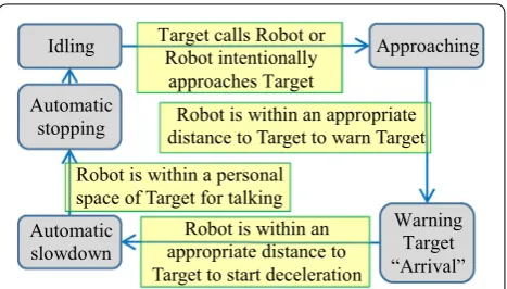
Figure 5 shows the model of Robot regarding the approach function by a state machine diagram in MBSE.
And, the following values were required by the model of Robot in Fig. 5.
• An appropriate distance to Target at which to stop
• An appropriate distance to Target to start decelera-tion
• An appropriate distance to Target to give a warning
We assumed that determining a personal space for talk-ing would give an appropriate distance to Target at which to stop, because Robot approached Target to talk with. We examined the idea of such a personal space by conducting an experiment with 7 test participants. We measured the personal spaces by having each test participant approach a standing person and adjust the distance to the person by moving back and forth on foot, in a wide hallway.
Table 3 shows the result of the survey of the personal space for talking.
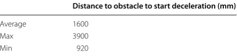
We assumed that a distance to an obstacle where a person starts deceleration would be an appropriate dis-tance to Target for Robot to start deceleration, because we assumed that the distance to the obstacle was impor-tant for deciding to start the deceleration, when person and obstacle were getting closer at a velocity slower than a pedestrian.
Therefore, we surveyed the distance to an obstacle at which a person started deceleration in an experiment with 7 test participants by LRF unit. We measured the distance by examining how the test participants steered a service robot with their eyes at an average velocity of 860 mm/s as Robot approached an obstacle from the front in a wide hallway.
Table 4 shows the results of the distance to obstacle in the front at which the participants started deceleration.
Stop Walk
Start mobile
phone operation Stop
mobile phone operation
Walking attentively
Standing
inattentively inattentivelyWalking Monitoring
environment Standing
attentively
Be warned Be warned
Stop Walk Walk
Stop
Start mobile
phone operation
Stop mobile
phone operation
Fig. 4 Model of Target by state machine diagram
Target calls Robot or Robot intentionally
approaches Target
Approaching
Robot is within an appropriate distance to Target to warn Target Robot is within a personal
space of Target for talking Idling
Automatic stopping
Automatic slowdown
Warning Target “Arrival” Robot is within an
appropriate distance to Target to start deceleration
Fig. 5 Model of Robot regarding approach function by state machine diagram
Table 3 Personal space for talking
Personal space for talking (mm)
Average 700
Max 900
We assumed that a distance getting closer to Target during a reflex time of Target would be an additional dis-tance to the disdis-tance at which starting deceleration for adjusting the appropriate distance to warn Target.
Then we surveyed the reflex time from a warning sound until Target reacted to the sound in an experiment with 10 test participants. Therefore, we measured the reflex time from a warning sound until a button released as the reaction.
Table 5 shows the results of the reflex time measurements.
Next, for designing the approach function for both attentive Target and inattentive Target, we clarified dif-ferences in their behaviors.
And then, we researched a way to distinguish inatten-tive Target from atteninatten-tive Target. As a typical behavior of the inattentive Target, we focused on mobile phone oper-ation. For distinguishing inattentive Target from atten-tive Target, we surveyed the pose of people operating a mobile phone.
Figure 6 illustrates the poses of people; the left draw-ing shows a figure not operatdraw-ing a mobile phone, and the right drawing shows a figure operating a mobile phone.
In Fig. 6, we focused on the ratio of “Hah − Heh” to “Sh − Heh”, and the ratio of “Hav − Ev” to “Sv − Ev” to distinguish the pose of inattentive Target operating a mobile phone from the pose of attentive Target not oper-ating a mobile phone, because we found that the hori-zontal component of a hand position was between the horizontal components of the shoulder and head, and the vertical component of a hand position was between the vertical components of the shoulder and the elbow, dur-ing mobile phone operation.
• Hh (%): Horizontal position of hand.
• Hv (%): Vertical position of hand.
Figure 7 illustrates the pose of Target operating a mobile phone, and the elements of the formulas (1) and (2).
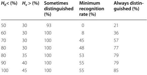
Therefore, we surveyed the pose of people operating a mobile phone with 14 test participants in an experiment in which the test participants approached Kinect unit on foot in a wide hallway. The data used in the analysis were stable readings made during the approach.
Table 6 shows the results regarding the pose of inat-tentive people operating a mobile phone. The “Always distinguished” column shows the proportion of test participants who were always recognized as operating a mobile phone. The “Sometimes distinguished” col-umn shows the proportion of test participants who were sometimes recognized as operating a mobile phone. The “Minimum recognition rate” column shows the mini-mum recognition rate of mobile phone operating poses in all of test participants.
For distinguishing the pose of Target operating a mobile phone from the pose of Target not operating a
(1) Hh=
Hah−Heh Sh−Heh
∗100
(2)
Hv = Hav −Ev
Sv−Ev
∗100 Table 4 Distance to obstacle to start deceleration
Distance to obstacle to start deceleration (mm)
Average 1600
Max 3900
Min 920
Table 5 Reflex time from warning sound until reaction
Reflex time (s)
Average 1.1
Max 1.4
Min 0.86
Head (Heh,Hev) Shoulder (Sh,Sv)
Elbow (Eh,Ev) Hand (Hah,Hav) People not operating
mobile phone People operating mobile phone
Fig. 6 Poses of people
Head (Heh,Hev) Shoulder (Sh,Sv)
Elbow (Eh,Ev) Hand (Hah,Hav) Sh - Heh
Hah - Heh
Sv - Ev
Hav - Ev
mobile phone, we chose a combination of Hh and Hv val-ues on the basis of the conditions as follows:
• A hand locates close to the center of the body in the horizontal axis.
• A hand locates higher than elbow in the vertical axis.
• All test participants sometimes satisfies the combina-tion of Hh and Hv.
• The minimum recognition rate of the combination of
Hv and Hv in all test participants is over 50 %.
By the result of experiment, we chose the combination of (Hh < 80 %) and (Hv > 35 %) as the values distinguish-ing the pose of people operatdistinguish-ing a mobile phone from the pose of people not operating a mobile phone.
Produce design solutions to meet user requirements for MBS on RTM
As the 3rd step of MBD/UM as HCD cycle, a design solu-tion has to be produced to meet the user requirements. Therefore, we produced a design solution of the approach function on Robot for MBS on RTM to meet the user requirements.
For producing a design solution of the approach func-tion for both attentive Target and inattentive Target, we surveyed the required abilities to the approach func-tion suitable for both attentive and inattentive Target, and then, we assumed that Robot had to have abilities to distinguish the poses of inattentive Target from atten-tive Target, to measure distances to Target, and to warn Target. And for simplifying an environment of approach function, we supposed that Robot would approach Target in a wide indoor hallway.
Figure 8 shows the environment where Robot approaches.
And then, we designed a hardware configuration of Robot with the abilities to recognize the pose of Target, to measure the distance to Target, and to warn Target in
addition to a basic ability to move Robot, based on the model of Robot shown in Fig. 5.
Therefore, we adopted Kinect unit to recognize and distinguish the pose of Target in Kinect subsystem, the laser range finder (LRF) unit to measure the distance to Target in LRF subsystem, a speaker unit to warn Target in Warning for Target subsystem, and a drive unit to move Robot in Motor drive subsystem.
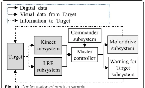
Figure 9 shows a hardware configuration of Robot. And then, we defined the configuration of product sample including the environment of the approach func-tion on RTM. This configurafunc-tion consisted of Robot and Target. And Robot consisted of Commander subsystem, Kinect subsystem, LRF subsystem, Master controller, Warning for Target subsystem and Motor drive subsys-tem as follows:
• Commander subsystem specifies movements of Robot, by a velocity.
• Kinect subsystem analyzes the pose of Target, and then outputs the attentiveness of Target as the result of analysis.
• LRF subsystem analyzes the distance to Target, and then outputs the size of Target, the relative position to Target, and the relative velocity to Target as the results of analysis.
• Master controller evaluates information from Com-mander subsystem, Kinect subsystem and LRF sub-system, and then outputs an appropriate velocity and an appropriate warning level as results of approach function. And, Master controller also has an ability to visualize movements and positions of Robot and Tar-Table 6 Pose of inattentive people operating mobile
phone
Hh< (%) Hv > (%) Sometimes
distinguished (%)
Minimum recognition rate (%)
Always distin‑ guished (%)
50 30 93 0 21
60 30 100 8 36
70 30 100 45 57
80 30 100 48 77
80 35 100 53 79
90 40 100 55 79
100 45 100 55 85
Recognize pose
Robot Target
Measure distance Warn
Move
Fig. 8 Environment where Robot approaches Target
LRF subsystem Motor drive subsystem Warning for Target subsystem
Kinect subsystem
get, and key values for monitoring a simulation status and an experiment status.
• Warning for Target subsystem warns Target with the warning level specified by input.
• Motor drive subsystem moves Robot with the veloc-ity specified by input.
• Target is monitored by Kinect subsystem and LRF subsystem, and is warned by Warning for Target sub-system. And Target monitors a distance to Robot, and then recognizes a velocity of Robot.
Figure 10 shows the configuration of the product sample.
On the basis of Fig. 10, we defined a configuration of design solution for MBS. This configuration consisted of a device model of Robot and UM of Target with sensor subsystems. And the device model of Robot consisted of Commander subsystem, Warning for Target subsystem, Motor drive model subsystem, and Master controller. And, UM of Target with sensor subsystems consisted of Target, Kinect subsystem, and LRF subsystem.
Figure 11 shows the configuration of the design solu-tion for MBS.
And then, we defined variables and formulas as follows. The subscript x means the direction for Robot to move.
1. TDxpersonal space [mm]: Personal space of Target as the appropriate distance to Target for Robot to stop. 2. TDxstart deceleration [mm]: Appropriate distance to
Tar-get for Robot to start deceleration.
3. TDxslowdown [mm]: Specified distance to Target for Robot to start slowdown.
4. tn [s]: Time from when Robot started movement. 5. tnstopped [s]: Time when Robot stopped.
6. tnwarned [s]: Time when Robot warned Target.
7. tnapproach [s]: Time from when Robot started decelera-tion.
8. Tvxabsolute (tn) [mm]: Velocity of Target. 9. TAt(tn) [s]: Attentiveness of Target.
10. Cvxspecified(tn) [mm/s]: Velocity being specified by Commander subsystem.
11. TDxrelative(tn) [mm]: Distance to Target from Robot, which is measured by LRF subsystem. And this value is calculated by UM of Target in MBS with following formula.
12. Tvxrelative(tn) [mm/s]: Relative velocity to Target from Robot.
13. Dxnotify(tn) [mm]: Distance to Target from Robot where Robot warns Target.
14. Dxapproach(tn, tnapproach) [mm]: Distance to the border of personal space of Target from Robot when Robot is approaching.
15. Rvxabsolute(tn) [mm/s]: Velocity of Robot. If TD x
relative(t
n) > D xnotify (tn) then Robot keeps specified velocity as follow.
Else if TDxrelative(tn) > TDxpersonal space then Robot decelerates as follow.
(3)
TDrelativex (tn)=TDrelativex (tn−1)−Tvxrelative(tn−1)
∗(tn−tn−1)
(4) Tvrelativex (tn)=
TDrelativex (tn−1)−TDxrelative(tn) tn−tn−1
(5)
Dnotifyx (tn)=TDslowdownx +TAt(tn)∗Tvrelativex (tn)
(6)
Dapproachx (tn,tnapproach)=D notify
x (tn)−TDpersonalspacex
−Tvxrelative(tn−1)∗
tnapproach−tnapproach−1
(7) Rvabsolutex (tn)=Cvspecifiedx (tn)
(8)
Rvabsolutex (tn)=Rvabsolutex (tn−1)
∗
1−Rv
absolute
x (tn−1)∗(tn−tn−1) Dapproachx
�
tn−1,t approach n−1
�
Master
controller LRF
subsystem Target
Motor drive subsystem Commander
subsystem Digital data
Visual data from Target Information to Target
Kinect subsystem
Warning for Target subsystem
Fig. 10 Configuration of product sample
Master controller UM of Target with
sensor subsystems
Motor drive model subsystem Commander
subsystem Digital data flow
Warning for Target subsystem
Else Robot stops as follow.
16. PHSat stop [0worst – 1best]: Physical safety of Target at stop, by the ratio of actual distance when Robot stopped to the appropriate distance determined by the personal space. 0 means that Robot collided Tar-get.
17. PSSat warned [0worst – 1best]: Psychological security of Target at warned, by the ratio of actual distance when Robot warned Target to the appropriate dis-tance to warn. 1 means that Target became attentive at the appropriate distance.
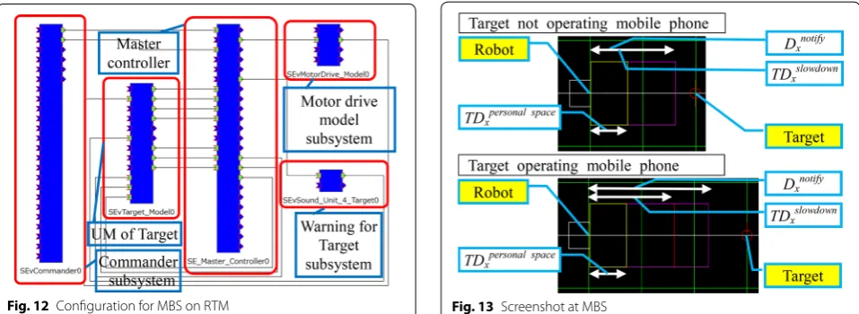
On the basis of the configuration shown in Fig. 11, we defined a configuration of design solution for MBS on RTM.
Figure 12 shows the configuration for MBS on RTM.
• Motor drive model subsystem consists of SEvMo-torDrive_Model0.
• Warning for Target subsystem consists of SEvSound_ Unit_4_Target0.
• Master controller consists of SE_Master_Control-ler0.
• Commander subsystem consists of SEvCommander0.
• UM of Target with sensor subsystems consists of SEvTarget_Model0.
(9)
Rvabsolutex (tn)=0
(10)
PHSatstop=
TDrelativex tnstopped
TDpersonalspacex
(11)
PSSatwarned
=
TDrelative x
twarned n
TDstartdeceleration x +TAt
twarned n
∗Tvrelative x
twarned n
Evaluate the designs against requirements by MBS on RTM As the 4th step of MBD/UM as HCD cycle, design solu-tions have to be evaluated against the user requirements. Therefore, we evaluated the design solution against requirements by MBS on RTM with the configuration shown in Fig. 12.
Figure 13 shows a screenshot at MBS by the ability to visualize movements and positions of Robot and Tar-get, and the ability to visualize distances from Robot for notifying, for starting deceleration, and for stopping.
In Fig. 13, “Robot” is the position of the center of the front of Robot, “Target” is the position of the center of the front of Target, Dxnotify is the calculated distance for notification, TDxslowdown is the specified distance for start-ing deceleration, and TDxpersonal space is the specified dis-tance to stop by the personal space of Target.
Produce product sample on RTM
As the 1st additional step to HCD process in MBD/UM, a product sample has to be produced on the basis of the design solution. Therefore on the basis of the configura-tion of product sample shown in Fig. 10, we produced a product sample on RTM by using a concierge-type robot developed by Vector Inc., Japan as the base of Robot.
Basic hardware specifications of Robot are as follows: • External dimensions: Width 455 mm / Depth
455 mm / Height 1200 mm.
• Maximum velocity: 500 mm/s. (By pre-experiment) The specifications of Kinect unit are as follows: • Operation range: 0.8–3.5 m.
• Field of view: Horizontally 58° / Vertically 45° / Diag-onally 70°.
The specification of LRF unit is as follows:
• Maximum measuring distance and angle: 5600 mm / 240°.
Figure 14 shows the configuration of the product sam-ple on RTM. We replaced UM of Target with sensor sub-systems by LRF subsystem and Kinect subsystem, and replaced Motor drive model subsystem by Motor drive subsystem.
• LRF subsystem consists of SEvLRF_Monitor0 and LRFCapture_URG0 (from the National Institute of Advanced Industrial Science and Technology).
• Kinect subsystem consists of SEvKINECT_Monitor0 and RT_Kinect_UserTracking0 (from the National Institute of Advanced Industrial Science and Tech-nology).
• Motor drive subsystem consists of TRobotRTC0 (from the Tokyo Metropolitan Industrial Technology Research Institute).
Certify the product sample on RTM
As the 2nd additional step to HCD process in MBD/UM, the product sample has to be certified to meet against user requirements. At first, we verified the compat-ibility of each actual subsystem with hardware in Fig. 14
with the corresponding subsystem by model in Fig. 12, by replacing the subsystem by model with the actual subsystem(s) with hardware, in Fig. 12. In this way, we certified the compatibility of LRF subsystem and Kinect subsystem with UM of Target with sensor subsystems, and the compatibility of Motor drive subsystem with Motor drive model subsystem.
After the verification of each subsystem, we certified the product sample on RTM with the configuration in Fig. 14.
Figure 15 shows the screenshots of pose of an attentive Target not operating a mobile phone and an inattentive Target operating a mobile phone by Kinect unit.
Results
This section shows the results of evaluation of the design solution and the result of certification of the product sample.
Results of evaluation by MBS
We evaluated the design solution against requirements by MBS, with the configuration shown in Fig. 12. In this study, Robot was smaller and slower than typical adults, then we assumed that we could apply the values and formulas derived from the surveys with test participants as follows:
• Cvxspecified(tn) [mm/s]: 470. 470 mm/s is the velocity specified at evaluation and certification.
• Tvxabsolute(tn) [mm/s]: 0. 0 mm/s means that UM of Tar-get is standing.
• TDxpersonal space[mm]: 700. 700 mm is the average dis-tance of the result of the survey on personal space for talking shown in Table 3 as the appropriate distance to stop for UM of Target.
• TDxslowdown [mm]: 700/1600. We studied the differ-ences in the sense of psychological security between the sudden stop and the decelerated stop. 700 mm was the value for the experiment of sudden stop around the border of personal space, and 1600 mm was the aver-age value of distance to start deceleration shown in Table 4 as the appropriate distance to start deceleration for UM of Target. 1600 mm was the average distance to start deceleration at the average velocity of 860 mm/s. We assumed that this average distance could be applied also at the velocity of 470 mm/s because we assumed that the distance for deceleration from 470 mm/s would be shorter than the distance for deceleration from 860 mm/s.
• TAt (tn) [s]: 0.0/1.4. We studied the differences in psy-chological security between attentive Target and inat-tentive Target. 0.0 s was the reflex time of atinat-tentive
get, and 1.4 s was the worst reflex time of inattentive Target in Table 5 for UM of Target.
Table 7 shows the result of the evaluation by MBS. By the result, we confirmed that TDxrelative at which a warn-ing was issued was similar to Dxnotify and that TDxrelative at which a stop was issued was similar to TDxpersonal space .
Table 8 shows the result of the evaluation regarding physical safety and psychological security. By the result, we confirmed that PHSat stop was always very good and PSSat warned was very good when Robot approached by deceleration.
Results of certification of product sample
We certified the approach function on the product sam-ple with 4 test participants. For comparing results at cer-tification with the results at the evaluation, we applied the same values and the same formulas which we applied at evaluation as follows:
• Cvxspecified (tn) [mm/s]: 470
• Tvxabsolute (tn) [mm/s]: 0 (Test participant was stand-ing.)
• TDxpersonal space [mm]: 700
• TDxslowdown [mm]: 700/1600
• TAt (tn) [s]: 0.0/1.4
Table 9 shows the result of certification by experiment. By the result, we confirmed that TDxrelative at which Robot warned was similar to Dxnotify , and TDxrelative at which Robot stopped was similar to TDxpersonal space, as we pro-duced the sample product.
Table 10 shows the result of certification regarding physical safety and psychological security. By the result, we confirmed that PHSat stop was always very good and PSSat warned was very good when Robot approached by deceleration.
The approach function on the product sample was cer-tified safely with the test participants. And the results at the certification were very similar with the results at the evaluation by MBS.
And by a questionnaire after the examination in the certification, we also surveyed the psychological security
when Robot stopped and the sense of time which Robot took till stop.
Table 11 shows the result of the questionnaire regard-ing the psychological security and the sense of time till stop.
By the result of questionnaire, we confirmed that the psychological security was very good and the sense of time till stop was appropriate for both the attentive Tar-get and the inattentive TarTar-get, when Robot decelerated to a stop. And we also found that the psychological secu-rity was inadequate when Robot stopped suddenly even though the distance to Target was similar to that in the case of Robot stopping under deceleration.
And the tendencies of the answers to the question regarding the psychological security were similar to the tendencies of the results of PSSat warned in the experiment. This means that PSSat warned could be used as an evalua-tion criteria of psychological security.
Discussion
We studied the approach function with physical safety as the usability and psychological security as UX on Robot by using MBD/UM for HCD.
At first, we understood and specified the context of use by Persona. Persona was found to be effective to describe a profile of user and context of use of Robot because Per-sona could be a user profiling method.
And we specified user requirements by MBSE. MBSE was effective to describe the user requirements and mod-els because the user requirements and the modmod-els could be defined by various diagrams in MBSE, such as the require-ment diagram and the state machine diagram.
Then, we produced a design solution to meet user requirements for MBS on RTM. For producing the design
Table 7 Result of evaluation by MBS
TAt TDxpersonal space (mm) TDxslowdown (mm) Dxnotify (mm) TDxrelative at warned (mm) TDxrelative at stop (mm)
0.0 700 700 700 675 675
1.4 700 700 1358 1276 697
0.0 700 1600 1600 1599 700
1.4 700 1600 2258 2203 700
Table 8 Physical safety and psychological security at MBS TAt TDxpersonal space (mm) TDxslowdown (mm) PHSat stop PSSat warned
0.0 700 700 0.96 0.42
1.4 700 700 1.00 0.57
0.0 700 1600 1.00 1.00
solution, MBD was effective to produce a device model of Robot and UM of Target as subsystems for MBS on RTM without the need for developing any new hardware.
And then, we evaluated the design against require-ments by using MBS on RTM, and we confirmed that the design solution met the user requirements.
After the evaluation of the design solution to meet the user requirements, we verified each actual subsystem in the configuration for MBS on RTM in Fig. 12, by replac-ing each subsystem by model in Fig. 12 with correspond-ing actual subsystem(s) with hardware in Fig. 14.
After verifying each actual subsystem, we produced a product sample on RTM by replacing all the subsystems by model with the corresponding actual subsystems with hardware and we certified the product sample on RTM.
The analyses of the results of the experiment and ques-tionnaires regarding the physical safety as the usability led us to the following conclusion:
• By the ability for Robot to stop automatically at the border of personal space, we could reduce the risk
for Robot to collide with Target; thereby, the physical safety was guaranteed.
Furthermore, we concluded the followings regarding the psychological security as UX:
• By the ability for Robot to decelerate to a stop at the appropriate distance, both the attentive Target and the inattentive Target felt that the time till stop was appropriate and the psychological security was very good. On the other hand, both the attentive Target and the inattentive Target felt that the time till stop was too short and the psychological security was very bad, against the sudden stop.
• By the ability for Robot to warn Target at the appro-priate distance that was adjusted by adding a distance related to a reflection time based on the attentiveness of Target, the inattentive Target could notice Robot approaching and became attentive. Therefore, in the case of the decelerated stop approach, the inatten-tive Target felt the same psychological security as the attentive Target felt. And even in the case of the sud-den stop approach, Target felt a little better psycho-logical security.
By the results of the analysis after certification, we also confirmed that we completed the approach func-tion on the product sample with the physical safety and psychological security for both attentive people and inattentive people in accordance with MBD/UM for HCD, with the ability to stop at the border of personal space, the ability to start deceleration at the appropriate Table 9 Result of certification by experiment
TAt TDxpersonal space (mm) TDxslowdown (mm) Dxnotify (mm) TDxrelative at warned (mm) TDxrelative at stop (mm)
0.0 700 700 700 657 657
1.4 700 700 1358 1332 689
0.0 700 1600 1600 1590 628
1.4 700 1600 2258 2237 700
Table 10 Physical safety and psychological security at cer-tification
TAt TDxpersonal space (mm) TDxslowdown (mm) PHSat stop PSSat warned
0.0 700 700 0.94 0.41
1.4 700 700 0.98 0.59
0.0 700 1600 0.90 0.99
1.4 700 1600 1.00 0.99
Table 11 Psychological security and sense of time till stop TAt TDxslowdown (mm) Psychological security
(1worst–5best)
Sense of time till stop (1long–3appropriate–5short)
Average Max Min Average Max Min
0.0 700 1.5 2 1 3.75 5 3
1.4 700 2.25 4 1 4 5 3
0.0 1600 4.75 5 4 2.5 3 2
distance, and the ability to warn Target at the appropri-ate distance according to the attentiveness of Target.
Conclusions
The aim of this study was to complete the approach func-tion which satisfied the user requirements on a con-cierge-type robot by applying MBD/UM as a practical HCD process with the advantages as follows:
• To reduce time and cost required to produce the hardware of the product sample at evaluation.
• To evaluate the product by simulation, under various conditions and also repeatedly under the same condi-tion.
• To eliminate risks injuring test participants in the evaluation, and to reduce the risks in the certifica-tion.
We completed the approach function on Robot which satisfied the user requirements by implementing the physical safety as the usability and the psychological security as UX, by MBD/UM for HCD.
By conducting evaluations with models without prod-uct sample until the design solution met the user require-ments, we reduced the time and cost required to produce the hardware of the product sample at evaluation of the approach function. And we could produce the product sample based on the design solution which had been evaluated by models.
By the evaluation with UM of attentive Target and inat-tentive Target, we confirmed that design solution could be evaluated by MBS under various conditions and also repeatedly under the same condition.
And by the evaluation with UM instead of actual stake-holder, we confirmed that MBD/UM eliminated risks to injure test participants at the evaluation. And then by the verification of each actual subsystem in MBS, we con-firmed that MBD/UM reduced risks to injure test partici-pants at the certification with the actual product sample and the actual stakeholder.
Then, we completed the study of the approach func-tion by MBD/UM as a practical HCD process with the advantages.
In the further study, we will continue to research the required functions on concierge-type robot including the functions for personalization, by MBD/UM for HCD. Authors’ contributions
YA led the study, directed the study, proposed the concept of the HCD process for service robots, designed the algorithms of the approach function, implemented the approach function on a service robot, conducted the
simulation and experiment, and analyzed the data of the simulation and experiment. ESS led the survey on the personal space for talking, and the survey on the appropriate distance to start deceleration. YF designed the hardware structure of the service robot, and implemented the components of the hardware on the service robot. TY provided the review of the user model. All authors read and approved the final manuscript.
Acknowledgements
The authors would like to express their deepest gratitude to all of question‑ naire respondents and test participants.
Competing interests
The authors declare that they have no competing interests.
Received: 12 January 2016 Accepted: 13 September 2016
References
1. Akimoto Y, Sato‑Shimokawara E, Fujimoto Y, Yamaguchi T (2014) An effec‑ tiveness of model‑based development with user model in consideration of human. In: Loo CK, Keem Siah Y, Wong KW, Beng Jin AT, Huang K (eds) ICONIP 2014: topics in artificial intelligence. 21st International Conference on neural information processing, Kuching, November 2014. Lecture notes in computer science (Lecture notes in neural information process‑ ing), vol. 8836. Springer, Berlin, pp 587–595
2. International Standardization Organization (2010) ISO 9241‑210:2010— Ergonomics of human‑system interaction—Part 210: Human‑centred design for interactive systems
3. Yamazaki K (2009) Approach to human centered design innovation by utilized paper prototyping. In: Masaaki K (ed) HCD 2009. First International Conference held as part of HCI International 2009, San Diego, July 2009. Lecture notes in computer science, vol. 5619. Springer, Berlin, pp 367–373 4. Wakizaka Y, Tomioka K, Ikemoto H (2005) Practice of universal design for
a front‑loading washing machine based on the human centered design processes. In: HCI International 2005. 11th International Conference on human‑computer interaction, Las Vegas
5. Peissner M, Dangelmaier M, Biswas P, Mohamad Y, Jung C, Kaklanis N (2012) White paper: virtual user modelling public document. Cluster on Virtual User Modelling and Simulation. http://vums.iti.gr/wp‑content/ uploads/2012/07/White‑Paperv2.pdf. Accessed 27 Dec 2015 6. VERITAS Project–FP 7 IP (2010) VERITAS Project–FP 7 IP Home. http://
veritas‑project.eu/. Accessed 27 Dec 2015
7. Digital Human Research Center, AIST (2003) Digital human for human centered design. http://www.dh.aist.go.jp/en/research/centered/. Accessed 27 Dec 2015
8. National Institute of Advanced Industrial Science and Technology (2001) AIST: About AIST http://www.aist.go.jp/aist_e/about_aist/index.html. Accessed 27 Dec 2015
9. Arima H, Nakamura Y, and Kurokawa F (2014) Development of a home energy system using model based development technology. IN: GCCE 2014. 2014 IEEE 3rd Global Conference on consumer electronics, Tokyo, October 2014. pp 740–743
10. Pruitt J, Adlin T (2006) The Persona lifecycle. Morgan Kaufmann, Burlington
11. Friedenthal S, Moore A, Steiner R (2008) A practical guide to SysML. Morgan Kaufmann, Burlington
12. Ando N, Suehiro T, Kitagaki K, Kotoku T, Yoon W.K (2005) RT‑middleware: distributed component middleware for RT (robot technology). IN: IROS 2005. 2005 IEEE/RSJ International Conference on intelligent robots and systems, Edmonton, August 2005. IEEE, pp 3933–3938