542 | P a g e
DESIGN OF MONO LEAF SPRING USING CAE
TOOLS WITH COMPOSITE MATERIAL
Amandeep
1,
Ketan Mittal
2 1(PG Scholar, Department of Mechanical Engineering
, JCDM College of Engineering, Sirsa, Hry., (India)
2(
Assistant Professor, Department of Mechanical Engineering,
JCDM College of Engineering, Sirsa, Hry., (India)
ABSTRACT
Weight reduction is now the main issue in automobile industries. Weight reduction can be achieved primarily by
the introduction of better material, design optimization and better manufacturing processes. The suspension leaf
spring is one of the potential items for weight reduction in automobile as it accounts for ten to twenty percent of
the unsprung weight, which is considered to be the mass not supported by the leaf spring. Since the composite
materials have more elastic strain energy storage capacity and high strength-to-weight ratio as compared to
those of steel, Composite material is taken into consideration. The objective of present work is to minimize the
deflection in the leaf spring and reduce the weight by changing the parameters i.e. size & shape. In the work the
model of leaf spring is designed in CATIA V5 software and saved in iges or stp format. The model is then
imported in Solid Works software and saved in Para solid (x_t) format file for no data loss. This Para solid file
of leaf spring is then imported in ANSYS workbench. The deformation and stress contours have been plotted and
the results obtained are compared with available results in literature survey. All these will result in fuel saving.
Keywords
:
ANSYS, CATIA V5, Composite Material, FEA, Leaf Spring
I. INTRODUCTION
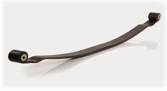
543 | P a g e Weight reduction has been the main focus of automobile manufacturers in the present scenario. The replacement of steel with optimally designed composite leaf spring can provide 92% weight reduction.[3] Moreover the composite leaf spring has lower stresses compared to steel spring. According to the studies made a material with maximum strength and minimum modulus of elasticity in the longitudinal direction is the most suitable material for a leaf spring. Fortunately, composites have these characteristics. The Arrangement of Leaf Spring shown in Figure 1.
Fig. 1 Mono Leaf Spring
II.
LITERATURE
Pradhan A. et al. (2016) performed the comparison of performance of various leaf spring material used in automobile industry. This work carry the modeling & analysis of the conventional steel (55Si2Mn90) & three composite leaf springs with the same loading & boundary condition.[3]
K. Kumar et al. (2015) optimized a mono parabolic leaf spring using CAE software. In this work It was shown that the use of composite material instead of steel resulted into large deflection, small variation in stresses and also a large amount of weight reduction [4].
Ashvini P. Lad. et al. (2015) performed the deflection analysis of steel leaf spring vs composite leaf spring through FEA software. The work carried out in this paper is to present analysis of deflection of composite leaf spring (Epoxy Carbon fiber) to the conventional steel leaf spring through FEA software ie in Ansys.[7]
Manjunath H.N et al. (2014) carried the static analysis & fatigue life prediction of composite leaf spring for a light commercial vehicle. In this research work an attempt has been made to check the suitability of composite materials like E Glass/Epoxy, Graphite/Epoxy, Boron/Al, Carbon/ Epoxy & Kevlar/ Epoxy for light commercial vehicle leaf spring.[6]
544 | P a g e
III.
METHODOLOGY
There are three steps in software based Finite Element Analysis- 3.1 Pre-processing
3.2 Analysis 3.3 Post processing
Figure 2 shows typical FEA procedures by commercial software.[2]
Fig.2 Typical FEA procedures by commercial software
3.1 Pre-Processing
Prepare Model
:
The first step is to prepare a CAD model of master leaf spring. The model of leaf spring isdesigned in CATIA V5 software and saved in iges or stp format. The geometrical specification of leaf spring is given in table 1[4].
Table 1 Specification of Leaf Spring
Span Length 940 mm
Number of Leaf 1
Rated Load 1500 N
Width of Leaf 60 mm
Centre Rubber Pad 100 mm X 50 mm X 5mm
545 | P a g e material is removed from the bottom of leaf spring up to thickness 1 mm as shown in Figure 3. The deformation and stress contours have find out using ANSYS workbench. The results obtained are compared with available results in literature survey.
Fig. 3 Leaf Spring Drawing after Modification
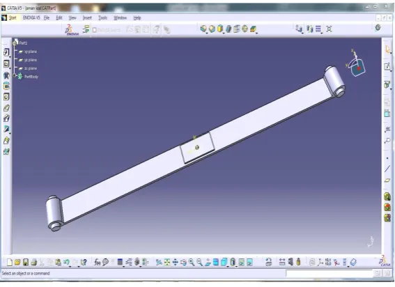
The Fig 4 shows the CAD model of leaf spring in CATIA V5 Software.
Fig. 4 CAD model of leaf spring
Mesh generation: Second step is to generate mesh using parabolic tetrahedral elements. An automatic method
546 | P a g e
Fig. 5 Meshed model of Leaf Spring in ANSYS workbench
3.2 Analysis
Boundary Conditions
:
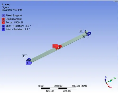
Third step is to apply boundary conditions. The boundary condition is the collection ofdifferent forces, supports, constraints and any other condition required for complete analysis. Applying boundary condition is one of the most typical processes of analysis. A special care is required while assigning loads and constraints to the elements. Boundary condition of the leaf spring involves the fixation of one of the revolute joint and applying displacement support at the other eye end of leaf spring. A joint rotation of 2.2° has been taken for both revolute joints considering the no load camber. Loading conditions involves applying a load of 1500 N at the centre of the leaf. As per specifications the spring is drawn at flat condition, therefore the load is applied in downward direction to achieve initial no load condition. The model under defined boundary conditions is shown in Fig 6[4].
Model Display: While applying the boundary conditions, it is necessary to view the model from different
angles Pre-Processor offers capabilities of rotating, smoothness, scaling, regions, active set, etc. for efficient model viewing and editing
.
Solution: The Solution phase deals with the solution of the problem according to the problem definitions. All
the tedious type of work of formulating assembling of matrices is done by the computer and finally displacements and stress values are given as output.
Fig. 6 Applied constraints on the Leaf Spring
3.3 Post- Processor:
It is a powerful user friendly Post-Processing program using interactive colour graphics. It has
extensive plotting features for displaying the results obtained from the Finite Element Analysis. One
picture of the analysis results (i.e. the results in a visual form) can often reveal in seconds what would
547 | P a g e
see the important aspects of the results that could be easily missed in a stack of numerical data. The
entire range of Post-Processing options of different types of analysis can be accessed through the
command/menu mode there by giving the user added flexibility convenience Employing state of art
image enhancement techniques facilitates the viewing of:
- Contours of stresses, displacements, temperatures etc, - Deform geometric plots, light source shaded plot, - Animated deformed shapes,
- Time-history plots,
- Solid sectioning hidden line plot and boundary line plot etc.
IV.
STATIC
STRUCTURAL
ANALYSIS
Static structural analysis is done in ANSYS workbench to find out the equivalent (von-mises) stress and total deformation. Fig.7 and Fig. 8 show equivalent (von-mises) stress and total deformation in the leaf spring.
548 | P a g e
Fig. 8 Total Deformation
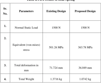
From the below comparison Table 2 it has been observed that for the same static load and boundary conditions, the deflection in the case of existing leaf is 71.724 mm while in case of proposed leaf it is 36.049 mm which shows that proposed leaf has less deflection in comparison to existing one. Also the value of von-mises stress has been decreased from the 501.26 MPa to 363.78 MPa. At the same time a weight also reduces from the 1.3716 kg to 1.0742 kg.
Table 2 FEA results of Leaf Spring
Sr.
No. Parameters Existing Design Proposed Design
1.
Normal Static Load 1500 N 1500 N
2.
Equivalent (von-mises)
stress 501.26 MPa 363.78 MPa
3. Total deformation in
mm 71.724 mm 36.049 mm
4. Total Weight 1.3716 kg 1.0742 kg
V.
CONCLUSION
Finite Element Analysis of the leaf spring has been done using ANSYS Workbench. From the results obtained from FE Analysis, many discussions have been made. The results obtained are well in agreement with the available existing results. The model presented here, is well safe and under permissible limit of stresses.
1. On the basis of the current work, it is concluded that the proposed material give sufficient improvement in the existing results.
2. The weight of the leaf spring is also reduced by 21.6 %, thereby reducing the cost. 3. The stress is found maximum near the hole and sharp edges.
REFERENCES
549 | P a g e [2] Kalyani Sudhir Kulkarni, V. J. Khot "Design and Development of Mono Leaf Spring by using Composite
Material (Epoxy-Carbon Fiber)" ISSN: 2349-6495,IJAERS Vol-2, Issue-12 , Dec- 2015
[3] P. Sainathan, K. Ajay "Modeling and Analysis of a Hybrid Mono-Leaf Spring Using FEA" ISSN: 2250-3153,IJSRP Vol 5, Issue 12, December 2015
[4] Trivedi Achyut V. , Prof. R.M. Bhoraniya “Static and Dynamic Analysis of Automobile Leaf Spring (TATA ACE)” ISSN (online): 2349-784X , IJSTE, Volume 1 , Issue 11 , May 2015.
[5] Krishan Kumar and M. L. Aggarwal “Finite element analysis and optimization of a mono parabolic leaf spring using CAE software” Engineering Solid Mechanics, 3, (2015).
[6] Manjunath H.N, Manjunath.K, T.Rangaswamy “Static Analysis and Fatigue Life prediction of Composite Leaf Spring for a Light Commercial Vehicle (TATA ACE)” ISSN:2319-6890, IJER, Volume No.3, Issue No.7, 01 July 2014.
[7] Ghodake A. P., Patil K.N. "Analysis of Steel and Composite Leaf Spring for Vehicle" ISSN: 2278-1684, IOSR-JMCE Vol 5, Issue 4, Jan 2013.
![Figure 2 shows typical FEA procedures by commercial software.[2]](https://thumb-us.123doks.com/thumbv2/123dok_us/9254223.1462733/3.595.196.407.227.477/figure-shows-typical-fea-procedures-commercial-software.webp)