IJEDR1702139
International Journal of Engineering Development and Research (www.ijedr.org)839
Design Of SoC Using 64 Bit RISC Processor For
Packaging Industry
1
Rupali V. Bhange,
2Yogesh M. Motey
1M.tech (VLSI),2Assist Prof (VLSI)1 Department of Electronics and Telecommunication, Nagpur, India
______________________________________________________________________________________________
Abstract—the era of industrialization, technological revolution reduced the intervention of humans to assist machinery. The
privatization slogan has increased the competition among industries which leads to origin of new products/designs for automation. The paper presents, one such, design and implementation of 64-bit RISC processor on SOC for industry automation, mainly useful for packing. The design includes processor with BIST features; it is a mechanism that allows a machine to test itself. Here RISC processor is used to decrease the number of instructions and they execute the instruction at faster rate. Later the design is integrated on System on Chip (SoC) to obtain a single chip which reduces the overall power consumption. The design and synthesis is done by verilog and verified in Altera Quartus 11.0 RTL compiler, SoPC Builder, Nios II SBT Eclipse, and Modelsim 10.1c.
Keywords-Industrial automation, reduced instruction set computer, system-on-chip, handling and packaging, synthesis, simulation, verification, hardware description language
________________________________________________________________________________________________________
I.INTRODUCTION .
Industrial Automation is an important market segment which deals with semi or complete automation of the industrial manufacturing machinery and associated tools. Microcontrollers have been playing an important role in Industrial Automation markets for performing automated tasks. For high-end process automation, the usage of customized or highly specific Programmable Logic Controllers and x-86 or Power-PC based Single Board Computers is common. Traditional RISC based Chipsets and System-on-Chip products have focused exclusively on Consumer Electronics and related fields. However, there is a compelling reason for having customized RISC based Chipsets which can cater to market verticals like Industrial Automation, Portable Instrumentation, Portable Medical and Point-of-Sale.
In these market segments, the traditional approach has been to utilize a general purpose RISC chipset which is then interfaced with custom ASIC to achieve the intended functionality for an Industrial Automation or Retail Point of Sale kind of End-Product. This approach not only increases the BOM cost, but limits the scalability of the product for future generations and OEM/ODMs end up spending significant amount of their R&D efforts in building new products for these markets. For example, let us consider the most common required interfaces for an Industrial Automation product i.e., ADC and CAN Interfaces. In traditional approaches, we would typically have the below mentioned configuration.
Depending on the logic implemented inside the custom ASIC/FPGA, the Analog Front End may be a separate/discrete IC or maybe implemented inside the custom ASIC itself. The above approach for designing products for Industrial Automation does not scale well and causes huge turn-around time for the Device Manufacturers whenever they are planning/ thinking of introducing new products into the market.
II.MOTIVATION
In this section, we will explore the motivation and the need to integrate a peripheral like the PRU (Programmable Real-time Unit) within the System-On-Chip and later examine one specific use-case of the PRU i.e., Communication Sub-system for Industrial Automation.
For real-time applications such as Programmable Logic Controllers, Control Machinery, the requirement to respond to real-time events is a critical one. If we take any modern System-On-Chip, they typically consist of at least two levels of Interconnect/bus and also multiple levels of cache/internal/external memory which makes it difficult to respond to real-time events within tens of nanoseconds.
So this introduces a kind of designer’s dilemma that while modern System-On-Chip offers the best connectivity/interfaces, cache and power requirements, at the same time cannot handle real-time events/processing within tens of nanoseconds. To overcome such performance issues, there has been one design argument that we need to integrate or merge Special Real-time Co-processors along with the regular RISC chipsets. This is analogous to integration of special purpose Audio/Video Co-processors to off-load the Audio/Video processing logic to custom real-time cores.
IJEDR1702139
International Journal of Engineering Development and Research (www.ijedr.org)840
This leads us to the second design conclusion that these Real-time Co-processors should also have their own interrupt Infrastructure and access to the external world via some kind of I/O Pins or serial interfaces. Typically providing access to at least some of the peripherals would also make the real- time coprocessor much more flexible in terms of integration and general usage.To summarize, the Real-time Coprocessor should meet/address the following requirements: 1. Have its own instruction execution unit independent of the RISC core
2. Should not utilize instruction pipeline cycles which will not guarantee real-time execution 3. Should have its own interrupt controller/mechanism to be able to detect real-time external events
4. Should have a separate instruction and data memory to ensure that the instruction fetch and data fetch are not multiplexed on the same lines
5. Should also have access to the external world via some General Purpose Pins or peripherals
6. Should preferably share the interconnect/external bus with the main RISC Core such that the real-time co-processor can also configure/control the memory mapped peripherals such as UART, PWM, SPI etc.
SOPC (SYSTEM-ON-A-PROGRAMMABLE-CHIP) BUILDER
SOPC builder is a powerful system development tools for creating systems based on processors, peripherals, interfaces and memories. SOPC Builder is implemented for the purpose of generating a complete system-on-a-programmable-chip (SOPC) by consuming less time than the accustomed integration methods.
Altera has SOPC Builder functionality built in Quartus II, which accordingly connects the soft-hardware components to construct a complete computer system that can be controlled on any of the FPGA chips and is also capable of producing interconnect logic automatically. It is outfitted with a library of built-in components such as a Nios II soft processor, memory controllers, interfaces, standard peripherals and custom peripherals.
In SOPC Builder, the system components are routed in a GUI (Graphical User Interface). The GUI is exclusive in configuring the soft-hardware components. It is a general-purpose tool for creating systems that includes a soft processor apart from the Nios II processor. It also contributes to writing software and system simulation
.
III.PROPOSED METHODOLOGY
Fig.1. illustrates the process of material handling and packaging system, which shall be automated using the programmable logic controller. This is a step by step process on which corresponds to the input and output peripherals that are needed in programming the ladder diagram. Included in the automation is the placement of box, filling of materials, transferring, checking, and sealing of the final product, or item. The overall design is implemented using an experimental prototype.
IJEDR1702139
International Journal of Engineering Development and Research (www.ijedr.org)841
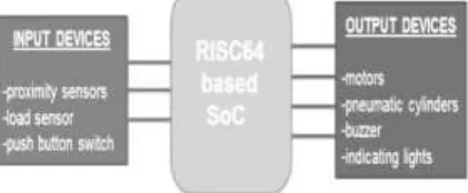
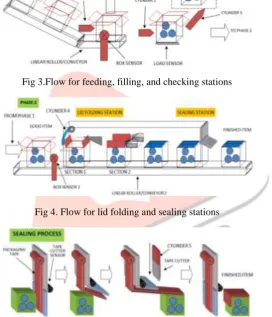
Fig 2.Conceptual Framework for AutomationFig. 2. Shows the general PLC block diagram used by the researchers to implement the automation of the system. From the manual operation, a programmable logic controller is used to convert the system into an automated process. Input components such as sensors and switches are used to indicate the condition corresponding to the hardware flow diagram of the PLC project design. The programmable logic controller interfaced the system and provided the ladder diagram for the design. Output components such as motors and pneumatic cylinders are used to indicate the desired objective of the system. Also, Fig. 3. shows the first phase of the system. As shown, it consists of three stations namely box feeding, the filling, and checking stations. The 2”x2”x2” card-board box is used as the object to be transported. The researchers used a small marble with the same weight to act as a sample material for experimental testing the prototype.
Fig 3.Flow for feeding, filling, and checking stations
Fig 4. Flow for lid folding and sealing stations
Fig 5.Sealing process station
Fig. 4 show the second phase of the design project. It is composed of two stations namely lid folding and sealing station. Fig. 5 illustrates the detailed automated process for the packaging station. A 1-inch width packaging tape is used to seal the boxes in a single linear direction. A proximity sensor is used to detect the length of the tape that will seal the boxes. A tape cutter made of stainless steel is also used in this station. Below is the discussion of whole operation:
1. When the start button is pressed, box shall be push under the hopper by cylinder 1.
2. Box sensor 1 is provided as to sense the presence of box under the hopper. When a box is detected, hopper motor runs, thus; dropping marbles to the box (box is stationary).
3. A counting sensor is provided as to monitor the correct number of marbles being drop to the box.
4. After the desired numbers of balls is dropped, a load sensor activates as to determine if the loaded box is overload, under load, or exact load. Good items are pushed to the next station, and phase by cylinder 2, while the under load box and the over load is pushed away from the line by cylinder 3, which is to be checked manually.
IJEDR1702139
International Journal of Engineering Development and Research (www.ijedr.org)842
6. When a box is sensed by box sensor 2, it shall activate cylinder 4, and folding the lid of the first section of the side of the box. 7. The second lid and section is folded, as the box moved on the specialized lid folding the obstacle, or as the box makes progress on the conveyor.8. Having a partially closed box, and a continuous running conveyor, it passes to the sealing station which finishes the packaging process. At this station, a packaging tape, and a cutter is positioned on a flip type window as to allow the incoming box to pass beneath it.
9. The tape cutter sensor shall be triggered, if the flip type window is moved from upward to downward position. This shall activate and turned the tape cutter to move downward via cylinder 5, and cut the tape.
10. Having finished the required task, the system shall point out if another process is to be commenced as invoke by the operator. 11. The finished item shall be collected at the end of the line by the on-duty personnel.
IV.IMPLIEMENTATION RESULTS
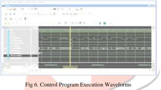
The control program for process control was implemented on the Nios SOPC and the testbench waveforms are shown below in figure 13. Process control data movement is shown on the data line.
Fig 6. Control Program Execution Waveforms
The receiver operation between the motion sensor and the Nios System is shown in figure 14. Object position vectors are transmitted by the motion sensor to the Nios System. The position vectors are 8 bit signals.
Fig 7. Motion Sensor Position Vector Waveforms
IJEDR1702139
International Journal of Engineering Development and Research (www.ijedr.org)843
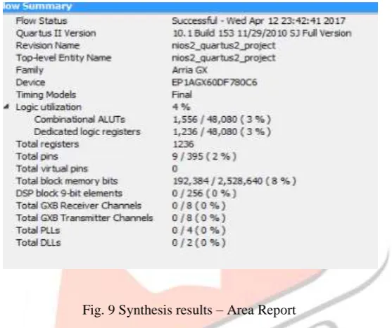
Fig. 8 Stepper Motor Control Vector WaveformsSynthesis results show that area requirement for the Nios based SOPC on an Arria GX FPGA is 4%. The estimated total power consumption is 776 mW. The timing analysis shows that minimum clock period is 8.6 ns. These results are shown in the synthesis and analysis figures 9, 10, and 11 shown below.
Fig. 9 Synthesis results – Area Report
The area results show that approximately 1500 LUTs and 1500 registers are required for design implementation out of a total available pool of 48000 LUTs and 48000 registers.
Similarly, the timing analysis report shows that apart from an 8.6 ns clock, the setup time achieved for the design is 7.2 ns and the hold time achieved is 0.2 ns. These are the worst case scenario results.
Fig .10 Timing analysis results
IJEDR1702139
International Journal of Engineering Development and Research (www.ijedr.org)844
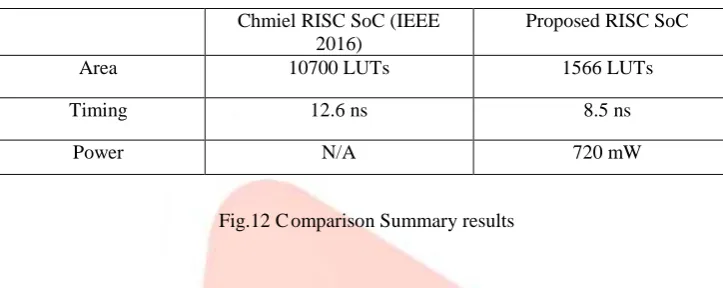
Fig .11 Power analysis resultsFig.12 C omparison Summary results
V.CONCLUSION
Today industrial automation software requirements include capability to implement applications involving widely distributed devices, high reuse of software components, formal verification that specifications are fulfilled. In this paper, an object oriented approach, the programming language together with a proper way to organize the inputs and outputs of FBs and supervisory control are proposed to implement industrial automation control systems to meet the new challenges of this field. A practical implementation of the above approach is realized and the results show the feasibility of this approach.
REFERENCES
[1] M. Amandine PIZZAGALLI, “Lithography technology and trends for Advanced Packaging”, Yole Développement, 75
Cours Emile Zola, 69100, Villeurbanne - Lyon, France, IEEE 2016.
J.ClerkMaxwell,ATreatiseonElectricityandMagnetism,3rded.,vol.2.Oxford:Clarendon,1892,pp.68–73.
[2] Miroslow chmiel, Wojciech kloska, Jan Mocha, “ FPGA based two processor CPU for PLC”, International conference on signals and electronic systems(ICSES), Sept 2016
[3] Ana Luisa Ramos, José Vasconcelos Ferreira and Fabio Bernardes, “Improving the Productivity of a Packaging Line Using Lean Manufacturing Tools and Simulation”, Proceedings of the 2015 International Conference on Industrial Engineering and Operations Management Dubai, United Arab Emirates (UAE), March 3 – 5, 2015.
[4] Joanna Marie M. Baroro, Melchizedek I. Alipio, Michael Lawrence T. Huang, Teodoro M. Ricamara, Angelo A. Beltran Jr., “Automation of Packaging and Material Handling Using Programmable Logic Controller”, International Journal of Scientific Engineering and Technology, Volume No. 3, Issue No. 6, pp.: 767 – 770. (ISSN: 2277 – 1581), 1 June 2014. [5] Francesco Basile, Senior Member, IEEE, Pasquale Chiacchio, Senior Member, IEEE, and Diego Gerbasio, “On the
Implementation of Industrial Automation Systems Based on PLC”, IEEE TRANSACTIONS ON AUTOMATION
SCIENCE AND ENGINEERING, 2013.
[6] Daniel Schütz, Andreas Wannagat, Christoph Legat, and Birgit Vogel-Heuser, Senior Member, IEEE, “Development of
PLC-Based Software for Increasing the Dependability of Production Automation Systems”, IEEE TRANSACTIONS
ON INDUSTRIAL INFORMATICS, VOL. 9, NO. 4, NOVEMBER 2013.
[7] W. Lepuschitz, A. Zoitl, M. Vallée, and M. Merdan, “Toward self- reconfiguration of manufacturing systems using automation agents,” IEEE Trans. Syst.Man Cybern. C, Appl. Rev., vol. 41, no. 1, pp. 52–69, Jan. 2011.
[8] P. Vrba, P. Tichy, V. Marik, K. H. Hall, R. J. Staron, F. P. Maturana, and P. Kadera, “Rockwell automation’s holonic and
multiagent control systems compendium,” IEEE Trans. Syst. Man Cybern. C, Appl. Rev., vol. 41, no. 1, pp. 14–30, Jan.
2011.
Chmiel RISC SoC (IEEE 2016)
Proposed RISC SoC
Area 10700 LUTs 1566 LUTs
Timing 12.6 ns 8.5 ns