Please cite this article as: M. K. Amirinejhad, M. Ranjbar, M. Karimkhany, Effects of Impeller Gap on Rotor Vibration in a High Speed Centrifugal Compressor: A Numerical and Experimental Analysis, International Journal of Engineering (IJE), TRANSACTIONS B: Applications Vol. 30, No. 5, (May 2017) 814-820
International Journal of Engineering
J o u r n a l H o m e p a g e : w w w . i j e . i rEffects of Impeller Gap on Rotor Vibration in a High Speed Centrifugal Compressor:
A Numerical and Experimental Analysis
M. K. Amirinejhada, M. Ranjbarb, M. Karimkhany*c
a Department of Mechanical Engineering, Islamic Azad University, Bushehr, Iran b Department of Mechanical Engineering, Razi University, Kermanshah, Iran c Department of Mechanical Engineering, Shahid Beheshti University, Tehran, Iran
P A P E R I N F O
Paper history: Received 08 October 2016
Received in revised form 12 December 2016 Accepted 10 March 2017
Keywords: Compressor Vibration High Speed Compressor Rotor Vibration Airflow Distribution
A B S T R A C T
Centrifugal compressors produce high pressure ratio and rotate at speeds. So, a tiny unbalance can produce severe vibration. In this paper, effects of impeller gap on rotor vibration in a high speed centrifugal compressor is investigated. For this purpose, a numerical and experimental analysis are carried out. The moving reference frame method in FLUENT software is used for modeling of geometries. Then, the motion of rotation components is introduced using UDF (User-Difined-Function) writing in C++ software and Define CG Motion macro. By using cloud points, three-dimensional geometry model of blades of this compressor is prepared. Finally, two-three-dimensional geometry of diffuser is added to blades and the final geometry is presented. Fluid flow inside the centrifugal compressor with and without considering blades vibration is studied. The numerical and experimental analysis of power spectrum density to determine the dominant vibration frequency cause of horizontal and vertical forces exerted on the compressor is studied. Results show that the dominant frequency of vibrations of forces exerted on the compressor is in the range of 9800 Hz, that is in good agreements with those reported by earlier researchers. Also, the main reason of centrifugal compressors shaft vibration is static and dynamic unbalance in shaft and other components of the compressor. In other words, the forces exerted on compressors blades do not affect the centrifugal compressor vibration. In the numerical studies, distribution of pressure, temperature, velocity and velocity vectors at different times are studied. Horizontal and vertical forces exerted on the compressor is represented. The mass flow rate of the compressor output for different cases of A/G ratio is presented and does not depend on amplitude of vibrations.
doi: 10.5829/idosi.ije.2017.30.05b.23
1. INTRODUCTION1
Centrifugal compressors have been more widely used in comparison with other types of compressors. Development of the compressors continued until 1950s. In those years, it became clear that in large cars, axial compressors will perform better than centrifugal ones. But, in the low rates, the efficiency of axial compressors can drop sharply. On the other hand, blades in this kind of compressor are small and manufacturing has its own limitations. In the 1960s, the need of military helicopters for small size turbines, centrifugal
*Corresponding Author’s Email: [email protected]
(M. Karimkhany)
compressors were led to the development. Following that, the high-speed centrifugal compressors were used in the military industries, oil and gas, power plants and refineries. It was optimized by using development of a computational code to check the performance of centrifugal compressors and constraints in designing [1]. Teipel and Wiedermann [2] developed the three-dimensional numerical code to determine the flow field in centrifugal compressors using Fortran programming language. To ensure the accuracy of numerical methods, Leboeufand et al. [3] obtained the results of their work by solving the three-dimensional numerical flow using RANS equations and compared them with experimental results. The results of their work reflected the strength of the fluid-flow modeling software to predict fluid flow
in the centrifugal compressors. Prasad et al. [4] did the numerical study of fluid flow in the centrifugal compressor. They studied the operation of compressor at different speeds (70%, 80%, 90%, 100% and 110% of the nominal round).As expected, the results of their work represent a reduction in compressor efficiency in a period of less or more than the nominal rounds. Ding and et al. [5] carried out a series of experimental investigations to study the effects of casing treatment on steady and transient performance of the compressor. Their results showed the improvement in compressor performance and the postponement of surge phenomena if holes are used in the frame. Eight low solidity vaned diffusers (LSVD1–LSVD8) were designed for a 240 kW centrifugal compressor [6]. Their experimental results proved the superior merits of the LSVDs relative to the vaneless and vaned diffuser. The effect of pulsating flow investigated by means of a steady gas-stand that was modified to produce engine-like pulsating flow [7]. Also, the effect of pressure pulses’ amplitude and frequency on the compressor surge line location was checked.
Pinarbasi [8] presented the three component hot wire measurements in the vaneless space and vane region of a low speed centrifugal compressor. The purpose of their study was to improve the understanding of the flow physics in a centrifugal compressor with vaned diffuser. Also, the mean 3-d velocities and six Reynolds stress components tensor used to determine the turbulence production terms which lead to total pressure loss [9].
A tandem impeller was designed to compensate for the volume flow increase for 2,2-Dichloro-1,1,1-trifluoroethane (HCFC123) [10] that absorbed the volume flow increase and also improved efficiency. Galindo et al. [11] carried out the experimental work that was focused on the measurement of compressor behavior within the surge zone by means of a specifically designed facility. Their model was based on the introduction of a fluid inertia term that accounted for the non quasi steady effects and the use of a compressor map extended to the surge and negative flows zone obtained from experimental tests. Jiang et al. [12] presented a dynamic model of a centrifugal compressor capable of system simulation in the virtual test bed (VTB) computational environment. Their model was based on first principles, i.e. the dynamic performance including the losses was determined from the compressor geometry and not from the experimentally determined characteristic performance curves. In their study, the compressor losses, such as incidence and friction losses, etc., were mathematically modeled for developing compressor characteristics. The CAD/CAM technologies for manufacturing centrifugal compressor impellers and turbine blades was investigated [13].
Sun et al. [14] developed the numerical methods for the performance analysis and the noise prediction of the centrifugal compressor impeller. An experimental study was described to explore the dominant sound generation mechanisms of the spectral components governing the overall noise level of centrifugal compressors [15]. Janson and et al. [16] carried out the experimental and theoretical analysis of unsteady flow phenomena in hydraulic turbines. Liu et al. [17] investigated three types of dynamic measurements (pressure, temperature and acoustic noise) to judge the surge points of compressor. Subramanian [18] examined numerically the influence of centrifugal growth on the rotor dynamic characteristics of a typical rotating labyrinth gas turbine seal.
In this research, the effect of vibrations of the rotor of the high speed centrifugal compressor on the distribution of velocity of airflow is investigated. For this purpose, a numerical and experimental analysis is carried out. The moving reference frame method in FLUENT software is used for modeling of geometries. Then, the motion of rotation components is introduced using UDF writing in C++ software and Define CG Motion macro. Finally, by solving unsteady fluid flow, network of solution is modified at any time. By using cloud points, three-dimensional geometry model of blades of this compressor is prepared. For simulation of two-dimensional geometry, a plate is passed from average height of blades and the image of intersection of this plate with the plate of blades is considered as the geometry of the blades. Finally, two-dimensional geometry of diffuser is added to blades and the final geometry is presented.
2. MODELING
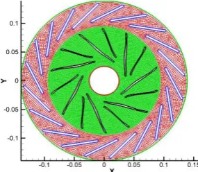
The centrifugal compressor in Iran's South Pars Gas Complex that is investigated in this paper. This compressor has three stages. In the first and second and third stage pressure increased to 1.2, 3.7 and 9.1 bars, respectively. There are three different methods in FLUENT software for numerical modeling of fluid flow with rotational coordinates that are: moving reference frame, sliding mesh and dynamic mesh. The moving reference frame method can be used in modeling of geometries with the variable of time. In order to use this method, we need to define the geometry of the solution. Then, the motion of rotation components is introduced using UDF writing in C++ software and Define CG Motion macro. Finally, by solving unsteady fluid flow, network of solution can be modified at any time. By using cloud points, three-dimensional geometry model of blades of this compressor is prepared and is shown in Figure 1. To simulate the two-dimensional geometry, a plate is passed from average height of blinds and the image of intersection of this plate with the plate of blades is considered as the geometry of the blades (Figure 2). On the other hand, in order to investigate rotor vibration effect on fluid flow distribution, diffuser of this compressor must be modelled.
The diffuser has 20 blades. Inner and outer diameters of this diffuser are 188.5 mm and 278.5 mm, respectively, and blades have 3.6 mm thickness and 60.4 mm length. Finally, two-dimensional geometry of diffuser are added to blades and the final geometry is shown in Figure 2. The networks used in numerical analysis of fluid flow within the compressor are shown in Figure 2.
3. REEULT AND DISCUSSION
3. 1. Fluid Flow Inside the Centrifugal Compressor Without Considering Vibrations of Blades
3. 1. 1. Numerical Studies Distribution of pressure, velocity and velocity vectors at different times are shown in Figures 3-5.
Figure 1. The three-dimensional geometry of the blades
Figure 2. The networks used in numerical analysis of fluid
flow within the compressor
In Figure 3, pressure at the tip of the diffuser blades is maximum; the main reason for this phenomenon is straight collision of airflow to those areas and shrinkage of duct of flow due to location of wheel blades near diffuser blades.
In this figures, high-pressure and low-pressure areas, in front of and behind the blades also can be seen clearly. Figure 4 shows the distribution of air velocity near the blades at different times.
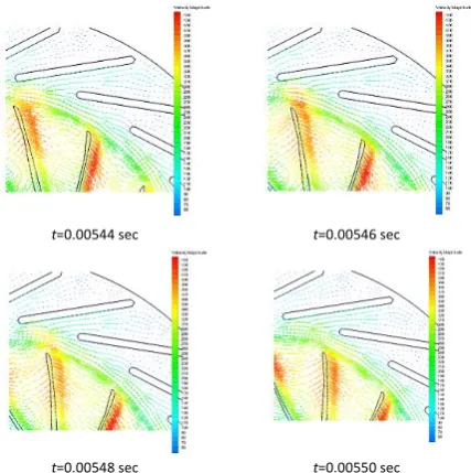
Also, Figure 5 shows the velocity vectors and distribution of velocity around the moving blades until the air access the diffuser blades. Horizontal and vertical forces exerted on the moving blades of compressor are calculated.
3. 1. 2. Convergence and Comparison Studies The boundary conditions that is used for modeling fluid flow in centrifugal compressor’s third stage is: input pressure 475 kpa, output pressure 850 kpa and the rotational speed 42500 rpm.
t=0.00546 sec
t=0.00544 sec
t=0.00550 sec
t=0.00548 sec
Figure 3. The distribution of pressure in blades at different
t=0.00546 sec
t=0.00544 sec
t=0.00550 sec
t=0.00548 sec
Figure 4. The distribution of velocity in blades at different
times
t=0.00546 sec
t=0.00544 sec
t=0.00550 sec
t=0.00548 sec
Figure 5. The distribution of velocity vector in blades at
different times
Power spectrum density to determine the dominant frequency of vibrations horizontal and vertical forces exerted on the moving blades of compressor is shown in Figures 6 and 7.
Also, the experimental power spectrum density to determine the dominant frequency of vibrations forces exerted on the moving blades of compressor is shown in Figure 8. This Figure shows that frequency of vibrations of blades of compressor is 42000 rpm that shows rotation velocity of compressor.
As can be seen from Figures 6-8, the dominant frequency of vibrations of forces exerted on the moving
blades of compressor is in the range of 9800 Hz that is in good agreements with those reported by earlier researchers.
By investigating the above-mentioned figures, we find that the main reason of vibrations of shaft of centrifugal compressor is static and dynamic unbalance in shaft and other components of the compressor. In other words, the forces exerted on the blades of the compressor does not have effects on the vibrations of centrifugal compressor.
Figure 6. The power spectrum density to determine the
dominant frequency of vibrations horizontal forces exerted on the moving blades of compressor
Figure 7. The power spectrum density to determine the
dominant frequency of vibrations vertical forces exerted on the moving blades of compressor
Figure 8. The experimental power spectrum density to
3. 2. Fluid Flow inside the Centrifugal Compressor with Considering Vibrations of Blades
3. 2. 1. Convergence and Comparison Studies Power spectrum density to determine the dominant frequency of vibrations of horizontal and vertical forces exerted on the compressor is shown in Figures 9 and 10. By using Labpulse measurement (vibration analyzer device) experimental analysis in time and frequency domain is done. Figures 9 and 10 sdominant frequency of vibrations of forces exerted on the moving blades of compressor is in the range of 9800 Hz that is in good agreements with those reported by earlier researchers.
By investigating these figures, we find that the main reason of vibrations of shaft of centrifugal compressor is static and dynamic unbalance in shaft and other components of the compressor. In other words, the forces exerted on the compressor’s blades does not affect the vibrations of centrifugal compressor.
3. 2. 2. Numerical Studies In this section, by considering the distance between the outer radius of the compressor impeller and the inner radius of the plate of diffuser (casing), three different cases are considered for A/G (A=amplitude and G=Gap). The frequency of vibrations of blades of compressor is considered 42000 rpm (700 HZ). The mass flow rate of the compressor output for different cases of A/G ratio is shown in Figure 11.
Figure 9. Power spectrum density to determine the dominant
frequency of vibrations of horizontal forces exerted on the compressor
Figure 10. Power spectrum density to determine the dominant
frequency of vibrations of vertical forces exerted on the compressor
Figure 11. The mass flow rate of the compressor output for
different cases of A/G ratio
The horizontal and vertical forces exerted on the moving blades of the compressor for different cases of A/G ratio are prepared. As can be seen, with increasing vertical vibrations amplitude of compressor, vibrations amplitude of forces exerted on the compressor in addition to its previous vibrations frequency (9800 HZ), has other frequency vibrations that is frequency vibrations of blades of compressor (700 HZ).
5. CONCLUDING REMARKS
In this paper, Effects of impeller gap on rotor vibration in a high speed centrifugal compressor is investigated. For this purpose, a numerical and experimental analysis was carried out. The moving reference frame method in FLUENT software was used for modeling of geometries. Then, the motion of rotation components was introduced using UDF writing in C++ software and Define CG Motion macro. Finally, by solving unsteady fluid flow, network of solution was modified at any time. By using cloud points, three-dimensional geometry model of blades of this compressor was prepared. For simulation of two-dimensional geometry, a plate was passed from average height of blades and the image of intersection of this plate with the plate of blades was considered as the geometry of the blades. Finally, two-dimensional geometry of diffuser was added to blades and the final geometry was presented.
Fluid flow inside the centrifugal compressor with and without considering vibrations of blades was studied. The numerical and experimental analysis of power spectrum density to determine the dominant frequency of vibrations of horizontal and vertical forces exerted on the compressor was studied.
Results have shown that the dominant frequency (the frequency that has maximum amplitude) of vibrations of forces exerted on the compressor is around 9800 Hz. Also, the main reason of shaft vibrations in centrifugal compressors is static and dynamic unbalance in shaft and other rotational components of the compressor.
multiplied by the rotor speed frequency. In addition, researches in this paper showed that the forces exerted on the compressors blades have a few effects on vibration amplitude in all frequencies include blade pass frequency (9800 Hz).
In numerical studies without considering vibrations of blades, distribution of pressure, temperature, velocity and velocity vectors at different times were studied. Results showed that pressure in the tip of the blades of diffuser was maximum. The main reason for this phenomenon was straight collision of airflow to those areas and shrinkage of duct of flow due to locating blades of impeller near blades of diffuser. High-pressure and low-pressure areas, in front of and behind the blades also were clearly observed. Results showed decreasing velocity after leaving them from the moving blades and the changes the output velocity of the moving blades interact with blades of diffuser. Horizontal and vertical forces exerted on the moving blades of compressor was represented.
In the numerical studies with considering vibrations of blades, with considering the distance between the outer radius of the wheel of the compressor and the inner radius of the plate of diffuser, three different cases were considered for A/G. The mass flow rate of the compressor output for different cases of A/G ratio was presented and mass flow rate of the compressor output didn’t depend on amplitude of vibrations.
The horizontal and vertical forces exerted on the compressor for different cases of A/G ratio were presented that cause increasing vertical vibrations amplitude of compressor, almost vibrations frequency around 9800 Hz that it is blade pass frequency of the compressor.
7. REFERENCES
1. Perdichizzi, A. and Savini, M., "Aerodynamic and geometric
optimization for the design of centrifugal compressors",
International Journal of Heat and Fluid Flow, Vol. 6, No. 1, (1985), 49-56.
2. Teipel, I. and Wiedermann, A., "A three-dimensional euler code for calculating flow fields in centrifugal compressor diffusers", Computers & Fluids, Vol. 19, No. 1, (1991), 21-31.
3. Leboeuf, F., Trébinjac, I., Ottavy, X. and Gourdain, N.,
"Aerodynamic studies in high-speed compressors dedicated to aeronautical applications", in 27th International Congress of The Aeronautical Sciences., 19-24.
4. Prasad, V.V., Kumar, M.L. and Reddy, B., "Centrifugal
compressor fluid flow analysis using CFD", Science Insight: An
International Journal, Vol. 1, No. 1, (2011), 6-10.
5. Ding, L., Wang, T., Yang, B., Xu, W. and Gu, C., "Experimental
investigation of the casing treatment effects on steady and transient characteristics in an industrial centrifugal compressor",
Experimental Thermal and Fluid Science, Vol. 45, (2013), 136-145.
6. Engeda, A., "Experimental and numerical investigation of the performance of a 240 kw centrifugal compressor with different
diffusers", Experimental Thermal and Fluid Science, Vol. 28,
No. 1, (2003), 55-72.
7. Galindo, J., Climent, H., Guardiola, C. and Tiseira, A., "On the
effect of pulsating flow on surge margin of small centrifugal
compressors for automotive engines", Experimental Thermal
and Fluid Science, Vol. 33, No. 8, (2009), 1163-1171.
8. Pinarbasi, A., "Experimental hot-wire measurements in a
centrifugal compressor with vaned diffuser", International
journal of heat and fluid flow, Vol. 29, No. 5, (2008), 1512-1526.
9. Pinarbasi, A., "Turbulence measurements in the inlet plane of a
centrifugal compressor vaneless diffuser", International journal of Heat and Fluid Flow, Vol. 30, No. 2, (2009), 266-275. 10. Nakagawa, K., Tanaka, S. and Kaneko, J., "An aerodynamic
investigation of a centrifugal compressor for HCFC123",
International Journal of Refrigeration, Vol. 15, No. 4, (1992), 199-205.
11. Galindo, J., Serrano, J., Climent, H. and Tiseira, A., "Experiments and modelling of surge in small centrifugal
compressor for automotive engines", Experimental Thermal
and Fluid Science, Vol. 32, No. 3, (2008), 818-826.
12. Jiang, W., Khan, J. and Dougal, R.A., "Dynamic centrifugal compressor model for system simulation", Journal of Power Sources, Vol. 158, No. 2, (2006), 1333-1343.
13. Chen, S.-L. and Wang, W.-T., "Computer aided manufacturing technologies for centrifugal compressor impellers", Journal of Materials Processing Technology, Vol. 115, No. 3, (2001), 284-293.
14. Sun, H., Shin, H. and Lee, S., "Analysis and optimization of aerodynamic noise in a centrifugal compressor", Journal of Sound and Vibration, Vol. 289, No. 4, (2006), 999-1018. 15. Raitor, T. and Neise, W., "Sound generation in centrifugal
compressors", Journal of sound and Vibration, Vol. 314, No. 3, (2008), 738-756.
16. Jansson, I., Åkerstedt, H.O., Aidanpää, J.-O. and Lundström, T.S., "The effect of inertia and angular momentum of a fluid annulus on lateral transversal rotor vibrations", Journal of Fluids and Structures, Vol. 28, (2012), 328-342.
17. Liu, A. and Zheng, X., "Methods of surge point judgment for
compressor experiments", Experimental Thermal and Fluid
Science, Vol. 51, (2013), 204-213.
Effects of Impeller Gap on Rotor Vibration in a High Speed Centrifugal
Compressor: A Numerical and Experimental Analysis
TECHNICAL NOTE
M. K. Amirinejhada, M. Ranjbarb, M. Karimkhanyc
a Department of Mechanical Engineering, Islamic Azad University, Bushehr, Iran b Department of Mechanical Engineering, Razi University, Kermanshah, Iran c Department of Mechanical Engineering, Shahid Beheshti University, Tehran, Iran
P A P E R I N F O
Paper history: Received 08 October 2016
Received in revised form 12 December 2016 Accepted 10 March 2017
Keywords: Compressor Vibration High Speed Compressor Rotor Vibration Airflow Distribution ديكچ ه اهروسرپمک ی رگ ی ز لااب راشف تبسن زکرم زا یی
لوت ی د هدرک نارود تعرس و ی
لااب یی مه هب ،دنراد ی ن لد ی ،ل دوجو ی ک مان ی ناز ی مرج ی م ،کچوک ی دناوت دش تاشاعترا ی د ی ا ی داج ا رد .دنک ی ن ثات ،هلاقم ی ر می ناز هلصاف هرپ اب د ی هراو ور رب ی تاشاعترا رد روتور ی ک روسرپمک رگ ی ز زا زکرم سررب ،لااب تعرس ی .تسا هدش هب نیا روظنم لانآ ی ز ددع ی امزآ و ی هاگش ی هدش ماجنا شور .تسا
MRF (Moving Reference Method)
رازفا مرن رد
FLUENT ارب ی لدم زاس ی سدنه ی هدافتسا
سپس .تسا هدش ،
ازجا تکرح ی کرحتم لدم هدش فیرعت عبات زا هدافتسا اب ی UDF (User-Defined-Function) رد هک نابز C++
ک تکرح ،تسا هدش هتشون ل ی CG اسانش ار یی م ی دنک زا هدافتسا اب .
Cloud Point
دعب هس لدم ی
اه هرپ ی م هتخاس روسرپمک ی
دوش اهن . ی ًات دعبود لدم ی د ی ف ی رزو هرپ لدم هب اه هفاضا هدش و لدم اهن یی م هتخاس ی دوش . رج ی نا روسرپمک رد اوه رگ
ی ز زا زکرم آ .تسا هدش هعلاطم روتور تاشاعترا نتفرگ رظن رد نودب و اب لان ی ز ددع ی و امزآ ی هاگش ی لاگچ زا ی طی ف ارب ناوت ی شان تاشاعترا هنماد هبساحم ی ن زا ی اهور ی قفا ی دومع و ی هعلاطم روسرپمک رب دراو
اتن .تسا هدش ی
ج م ناشن ی دنهد شان بلاغ تاشاعترا سناکرف هک ی
ن زا ی اهور ی رد ،روسرپمک رب دراو هنماد
9800
Hz
تسا
بوخ قباطت هک ی
قحت اب ی تاق گ هتشذ نچمه .دراد ی ن رتمهم ی ن لد ی ل تاشاعترا روتور ،روسرپمک ب ی لداعت ی تاتسا ی ک ی و د ی مان ی ک ی رد نآ روتور و اس ی ر ازجا ی راّود ب هب .تسا نآ ی نا د ی رگ ، ن ی اهور ی ثات ،روسرپمک هرپ رب هدراو ی
ر ی نآ تاشاعترا رب
ددع تاعلاطم رد .درادن ی
، زوت ی ع نامز رد تعرس و امد ،راشف اه
ی دش هعلاطم فلتخم ه ن .تسا ی اهور ی قفا ی دومع و ی دراو
م تبسن .تسا هدش هئارا روسرپمک رب ی ناز بد ی جورخ ی روسرپمک ارب ی داقم ی ر تبسن فلتخم A/G
هک تسا هدش هئارا
ن هتسباو نآ هب تاشاعترا هنماد رادقم ی
تس .