A Computerized Numerical System to Evaluate the
Effects of Skeletally Anchored Haas Palatal Expander
Tamer M. Nassef1,*, Amr E. Eldakroury2, Nagwa M. T. Mostafa3, Abou El yazeed M.3, Omnia A. Elhiny3
1Computer and Software Engineering Department, Misr University for Science and Technology, Giza, Egypt 2Orthodontcs Department, Cairo University, Cairo, Egypt
3Orthodontics and Pediatric Dentistry Department, National Research Centre, Giza, Egypt
Abstract
A three dimensional (3-D) model was generated from a Cone Beam Computed Tomography (CBCT) to evaluate the effects of skeletally anchored Haas palatal expander using finite element analysis, where the results present a high resolution 3-D model was obtained from the CBCT and revealed that low to moderate stress was obtained from the appliance with no stress concentration around the mini-screws. The study concluded that the appliance is a viable treatment option that produced stresses within the physiological limits.Keywords
Maxillary expansion, CBCT, Finite Element Analysis, Dental Modeling1. Introduction
Among the most remarkable aspects of palatal expansion is the predictability of the results following treatment [1]. Transverse dimension problems are dealt with usually by maxillary expansion through opening the mid-palatal suture by appropriate appliances. For an ideal maxillary expansion appliance, maximum skeletal and minimal dental effects are required. Unfortunately, most of the studies in the literature have concluded that the effects of maxillary expansion appliances are mostly dental in nature. The dento-alveolar effects are produced by the way the appliance is anchored. Haas stated that (The primary law of orthopaedics is “thou shalt utilize maximum anchorage to gain your orthopaedic objectives” [2]) but the dento-alveolar effect was unavoidable with the conventional appliance.
Recently, with the introduction of mini-implants a paradigm shift has occurred at the anchorage perspective. Conventional treatment mechanics have been enhanced by refining them with the use of mini-implants. As happening with every innovation, the learning curve is steep. Choosing the best way the mini-implant can enhance a certain treatment methodology needs a lot of trials and comparisons. Combining a traditional expansion appliance with mini- implant is one of these trials aiming to produce the desired maximal skeletal effect and a minimal dental one.
Finite element analysis is a numerical analysis method used to predict the effect of stresses on complex geometrical
* Corresponding author: [email protected] (Tamer M. Nassef)
Published online at http://journal.sapub.org/ajbe
Copyright © 2016 Scientific & Academic Publishing. All Rights Reserved
structures. There are broadly two types of application in biomechanical studies. The first is the analysis of stress and strain with a given force system that is applied to the teeth or the cranial complex. The second is the evaluation of the craniofacial growth with the given skeletal displacement observed during the growth changes [3]. Angel proposed the procedures of palatal expansion and it was consolidated clinically by Haas [1, 4].
The main Target of palatal expansion is the coordination of the mandibular and maxillary denture bases. The appliance should be designed to enhance the orthopedic movement and to decrease the orthodontic response.
El Dakroury et al [5], 2003, conducted a study to analyze the voice parameters of patients after rapid maxillary expansion using orthopaedic appliances or surgically assisted rapid maxillary expansion. They concluded that the encountered changes in voice parameters between the two groups are mainly due to different dental, muscular and skeletal responses in the two expansion procedures.
Mosleh et al [7], 2015, compared and evaluated the dentoskeletal effects of tooth-borne and 4-point bone-borne rapid maxillary expanders in growing children. They found that basal bone expansion at the level of the hard palate was produced by both expanders, more dental expansion, buccal rolling, and a greater increase in nasal width was produced by the tooth borne maxillary expanders, than did the bone borne maxillary expanders. It should be mentioned that the basis for modem finite element stress analysis was set down by Robert Hooke in 1678. It was firstly used in aerospace industry in the late sixties and in the early seventies it was applied in dentistry [8].
Boryor A. et al [9], 2010, used fresh and dried fixed human skulls to investigate the effects of high maxillary expansion forces on the skull. Only in one experiment the maxillary suture was not weakened. They also compared the strain measured on the zygomatic process of the skull with the results of a finite element model generated for this purpose. Increasing transversal force was applied on the alveolar process (teeth) until rupture. Maxilla displacement, the expanding forces and strain on the zygomatic process, were registered. They found that, during the experiments and FE simulation; the highest stress was observed on the alveolar process. They concluded that, the existence of appropriate models is important and that female specimens seem to rupture at a lower force than male ones. Specimens of both genders show a similar linear behavior in the force/strain curve within each gender group. There is a very low probability for opening of maxillary suture in adults during ultra-rapid maxillary expansion with tooth anchorage, also; complications and unwanted rupture could occur.
Cone beam computed tomography (CBCT) was presented by Mozzo et al [10] in 1998 as a new type of volumetric computed tomography. They evaluated radiation dose and accuracy of measurements and they concluded that this new system (CBCT) is very promising due to the good performances and low cost together with low radiation dose, which is interesting in view of large-scale use of the CT technique in such diagnostic application. Nassef et al [11-13] used the output of CT files to generate a 3-D finite element models and they conclude that Many clinicians find that the benefits of using CT in follow up outweighs the risks of increased radiation doses especially with modified scanners of lower radiation doses.
EI-Beialy et al [14], 2011, evaluated two methods of virtual 3-D skull the reliability and accuracy of different head orientations using three-dimensional CBCT scans. Twelve and eleven linear measurements respectively in the first and second methods, twelve distances were compared on the physical skull and the 3-D virtual skull in the centered and the other scanning positions in the first method, while in the second method, coordinates of 11 landmarks were identified in 5 different scanning positions. High concordance was seen between the CBCT centered-position measurements and the skull. Also a very high concordance was found between measurements of the centered relation to those from the different skull positions. They concluded that
changing the skull orientation did not affect the accuracy and reliability of CBCT measurements.
2. Construction of the Model
The selected patient was a male to benefit from the delayed longer maturation range compared to females, where their permanent dentition could be relatively completed while a considerable amount of skeletal growth remains [15].
The appliance is different from previously studied bone-borne appliances in corporation acrylic plates which provided a wider area for force application and a higher level of force near the center of resistance of each maxillary bone which is located superior and lateral to the distal root of the upper first molar [16]. Since the force is applied near or at the center of resistance, less or no moments are created. This moment is responsible for the dentoalveolar buccal rolling [17].
Nowadays CBCT gained more popularity [18], the advantages of this technology are fairly low cost, convenient machine size, 3D images of dentofacial regions, ease of operation, relatively quick scans and low radiation exposure as compared to traditional computed tomography [19-23].
During scanning, while the patient was closing in maximum intercuspation position, the cusps of upper and lower teeth intermingled in axial slices and it was hard to differentiate the end of a tooth and the beginning of the other, thus; the patient was asked to wear a splint made of thermoplastic material of 2 mm thickness.
I-CAT 3D cone beam imaging machine was used and DICOM files were exported to MIMICS software where image analysis was done by cropping the maxillary jaw with the full set of maxillary teeth, then segmentation mask was created by thresholding, were. Different tissues in the region of interest were identified through the selection of a range of grey values (Hounsfield unit).
Hounsfield unit (HU) is defined as: 𝐻𝐻𝐻𝐻= 1000𝜇𝜇−𝜇𝜇𝑤𝑤𝑤𝑤𝑤𝑤𝑤𝑤𝑤𝑤
𝜇𝜇𝑤𝑤𝑤𝑤𝑤𝑤𝑤𝑤𝑤𝑤 . (1)
Where, (μ) referred to the linear attenuation coefficient for
the respective material compared with water. The linear attenuation coefficient depends on parameters such as electron density, atomic number and the beam quality of the CBCT-scanner [25].
Manual editing functions facilitated drawing, modifying, erasing or restoring parts of images within the local threshold value of the mask. The axial, coronal and sagittal views as well as the 3-D mask were edited individually, then, the 3-D model was calculated and STL file files were exported to SolidWorks to get the geometrical outline.
images for contour interpolation which results in a 3-D that looks smoother and better (less gaps) [26], But in this study we were able to produce a smooth 3D with high resolution and fine topographic details.
In our study the palate showed the highest stresses with no stress concentration around the mini-screws which proves that the stresses were distributed over a large area and proved that the mini-screws did not receive all the stresses but functioned mainly as an anchorage for the appliance and the stresses were transmitted through the acrylic pads of the appliance. Stress present in the nasal floor and the displacement predicted in this area, supports the findings of
previous studies that found that there was significant increase in the nasal airway dimension following maxillary expansion which was related to expansion of the lateral nasal walls [27, 28]. It had been reported previously that some patients undergoing maxillary expansion feel pressure in the vault of the palate, in the region of the alveolar process, in the frontonasal region, under the eyes and generally throughout the face [28] this coincides with our findings, therefore, phenomena such as dizziness and a feeling of heavy pressure on the bridge of the nose, under the eyes and generally throughout the face can be explained.
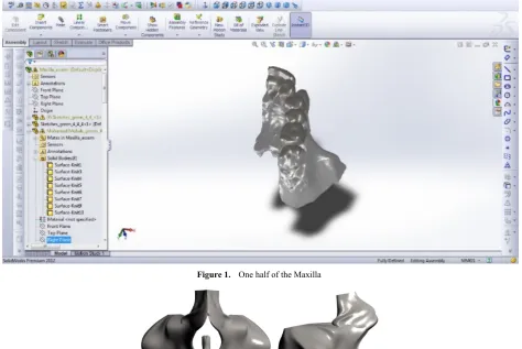
Figure 1. One half of the Maxilla
Figure 2. Mirrored Maxilla; (a) Frontal view, (b) Lateral view; (c) Palatal view, (d) Top view
d c
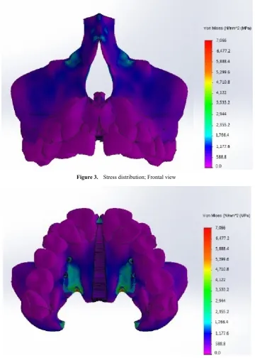
Figure 3. Stress distribution; Frontal view
Figure 4. Stress distribution; Palatal view
Table 1. Von Mises stress
Name of area Maximum stresses (Mpa)
Nasal floor 441.6
Zygomatico-alveolar crest 656.6
Orbital floor 1,510.4
Mid-paalatal suture 210.8 Maxillary tuberosity 710
Palate 2450
3. Results and Discussion
After running the analysis the results were collected, the results of interest were:
- Modelling - Stress distribution
3.1. Three Dimensional (3-D) Modelling
3.2. Stress Distribution
The results showed that collective stresses were all types of stresses occurred at each area at the same time so only Von Mises stress “equivalent stress” was calculated; Figures 3, 4. Mild to moderate stresses were produced by the appliance and there was no increase in stresses around mini-screws.
4. Conclusions
The skeletally anchored Haas palatal expander is a viable treatment option, where the results of the computerized numerical system showed no areas of high stress concentrations as they were distributed along a larger surface area by the acrylic pads and the mini-screws served mainly as an anchor. The application of the load must be at or as near as possible to the center of resistance of the maxilla and to achieve bone stress relaxation; the increasing relaxation time between two successive activations of the jackscrew is necessary. The limitations of this study involved several approximations in the material properties of the tissues. Since the material properties of the teeth do not affect the results significantly, all bony tissues were given the mechanical properties of cancellous bone and all teeth were given the properties of dentin. The finite element models did not include the whole skull, so the results represent only the response of that part of the craniofacial structure. Elements representing tissues were considered isotropic and solved with linear- elastic properties. It is not based on the individual skull geometry of each patient and it does not consider the different elastic modules of sutures during growth.
REFERENCES
[1] Andrew J. “Haas, Palatal expansion Just the beginning of dentofacial orthopedics,” Am J of Orthod 1970; 57(3): 219-255.
[2] Andrew J. Haas, “Rapid Expansion of the Maxillary Dental Arch and Nasal Cavity by Opening the Midpalatal Suture,” Angle Orthod 1961; 31: 73-90.
[3] Alireza Jafari et al, “Study of Stress Distribution and Displacement of Various Craniofacial Structures Following Application of Transverse Orthopedic Forces-A Three-dimensional FEM Study,” Angle Orthod 2003; 73: 12–20.
[4] Angell EH. “Treatment of irregularities of the permanent or adult teeth,” Dental Cosmos 1860; 1:540-544,599-600. [5] AE El Dakroury, WM Refai, AH Labib. “Voice variation
related to rapid maxillary expansion,” Egy. Orth. Journal 2003; 23: 27-42.
[6] Mohamed Ghoneim. “Three dimensional evaluation of the effects of skeletally anchored Haas palatal expander,” Cairo University. Faculty of Oral and Dental Medicine. Department of Orthodontics; 2011.
[7] Mennatallah Ihab Mosleh, Mohamed Amgad Kaddah, Fatma Abdou Abd ElSayed, Hend Salah ElSayed. “Comparison of transverse changes during maxillary expansion with 4-point bone-borne and tooth-borne maxillary expanders,” Am J Orthod Dentofacial Orthop 2015; 148: 599-607.
[8] Vandana KL and Kartik M.”Finite element method- perio-endo concept,” Endodontology; 2004; 16:38-41. [9] Boryor A, Hohmann A, Wunderlikch A, Geiger M. “In-vitro
results of rapid maxillary expansion on adults compared with finite element simulations,” Journal of Biomechanics 2010; 43: 1237-1242.
[10] .Mozzo P, Procacci C, Tacconi A, Martini PT, Andreis lA. “A new volumetric CT machine for dental imaging based on the cone-beam technique: preliminary results,” Eur Radiol 1998; 8: 1558-1564.
[11] T. M. Nassef, N. H. Solouma, M. Alkhodary, M. K. Marei and Y. M. Kadah, “Extraction of human mandible bones from multi-slice computed tomographic data,” 2011 1st Middle East Conference on Biomedical Engineering, Sharjah, 2011, pp. 260-263
[12] T. M. Nassef, R. M. Fliefel, M. K. Marei, N. H. Solouma and Y. M. Kadah, "Computer assisted determination of mandibular cystic lesion volume from computed tomographic data," 2011 1st Middle East Conference on Biomedical Engineering, Sharjah, 2011, pp. 92-95.
[13] Nassef, T.M. Computer-Assisted Tissue Engineering for Dental Applications: Multi-Object Reconstruction Technique. LAP Lambert Academic Publishing; February 2012.
[14] El-Bialy AR, Fayed MS, El-Bialy AM and Mostafa YA. “Accuracy and reliability of cone-beam computed tomography measurements: Influence of head orientation,” Am J Orthod Dentofacial Orthop 2011; 140:157-165. [15] Bishara SE, Staley RN. “Maxillary expansion: clinical
implications,” Am J Orthod Dentofacial Orthop, 1987; 91: 3-14.
[16] Proffit W, Fields H, Sarver D. “Contemporary orthodontics,” Mosby Elsevier; 2007.
[17] Lee KG, Ryu YK, Park YC, Rudolph DJ. “A study of holographic interferometry on the initial reaction of maxillofacial complex during protraction,” Am J Orthod Dentofacial Orthop, 1997; III: 623-632.
[18] Braun S, Bottrel JA, Lee KG, Lunazzi n, Legan HL. “The biomechanics of rapid maxillary sutural expansion,” Am J Orthod Dentofacial Orthop, 2000; 118:257-261.
[19] Moreira CR, Sales MA, Lopes PM, Cavalcanti MG. “Assessment of linear and angular measurements on three-dimensional cone-beam computed tomographic images,” Oral Surg Oral Med Oral Pathol Oral Radiol Endod, 2009; 108:430-436.
[20] Ballrick JW, Palomo JM, Ruch E, Amberman BD, Hans MG. “Image distortion and spatial resolution of a commercially available cone-beam computed tomography machine,” Am J Orthod Dentofacial Orthop, 2008; 134:573-582.
[22] Periago DR, Scarfe WC, Moshiri M, Scheetz JP, Silveira AM, Farman AG. “Linear accuracy and reliability of cone beam CT derived 3-dimensional images constructed using an orthodontic volumetric rendering program,” Angle Orthod, 2008; 78: 387-395.
[23] Silva MA, Wolf U, Heinicke F, Bumann A, Visser H, Hirsch E. “Cone-beam computed tomography for routine orthodontic treatment planning: a radiation dose evaluation,” Am J Orthod Dentofacial Orthop, 2008; 133:640 e641-645. [24] Brooks SL. “CBCT Dosimetry: Orthodontic Considerations,”
Seminars III Orthodontics, 2009; 15: 14-18.
[25] Tamer M. Nassef. “New Segmentation Approach to Extract Human Mandible Bones Based on Actual Computed Tomography Data,” American Journal of Biomedical Engineering, 2012; 2(5): 197-201.
[26] R. Moustafa, Tamer M. Nassef, M. Alkhodary, Mona K. Marei, Magdy A. Awadalla. “A New Interactive 3-D Numerical Model of the Human Mandible for Peri-Implant Analysis in-Vivo Compared With Cone Beam Computed Tomography 3-D Quality,” American Journal of Biomedical Engineering, 2012; 2(1): 9-16.
[27] Altug-Atac AT, Atac MS, Kurt G, Karasud HA. “Changes in nasal structures following orthopedic and surgical assisted rapid maxillary expansion,” Int. J. Oral Maxillofac Surg. 2010; 39: 129-135.