B.E SEM V (EXTC) Experiment No. 02 Page | 1
Name:
Department. :
EXTC
Class & Semester:
T.E (Third Year), Sem V
Subject:
OSTL (Open Source Technology Lab)
_________________________________________
Experiment No. 02
Aim:
To Implement Different Types Of Clampers
Using LTSpice.
Roll No:
Date:
Practical In-charge Sign:
B.E SEM V (EXTC) Experiment No. 02 Page | 2 AIM:
To Implement Different Types Of Clampers Using LTSpice.
Tools Used:
LTSpice
Description
: T
he positive or negative peak of a signal can be positioned at the desired level by using the clamping circuits. As we can shift the levels of peaks of the signal by using a clamper, hence, it is also called as level shifter.The clamper circuit consists of a capacitor and diode connected in parallel across the load. The clamper circuit depends on the change in the time constant of the capacitor.The capacitor must be chosen such that, during the conduction of the diode, the capacitor must be sufficient to charge quickly and during the nonconducting period of diode, the capacitor should not discharge drastically. The clampers are classified as positive and negative clampers based on the clamping method.
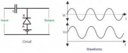
1. Negative Clamper
Negative Clamper
During the positive half cycle, the input diode is in forward bias- and as the diode conducts-capacitor gets charged (up to peak value of input supply). During the negative half cycle, reverse does not conduct and the output voltage become equal to the sum of the input voltage and the voltage stored across the capacitor.
2.Negative Clamper with Positive Vr
B.E SEM V (EXTC) Experiment No. 02 Page | 3
It is similar to the negative clamper, but the output waveform is shifted towards the positive direction by a positive reference voltage. As the positive reference voltage is connected in series with the diode, during the positive half cycle, even though the diode conducts, the output voltage becomes equal to the reference voltage; hence, the output is clamped towards the positive direction as shown in the above figure.
3.Negative Clamper with Negative Vr
Negative Clamper with Negative Vr
By inverting the reference voltage directions, the negative reference voltage is connected in series with the diode as shown in the above figure. During the positive half cycle, the diode starts conduction before zero, as the cathode has a negative reference voltage, which is less than that of zero and the anode voltage, and thus, the waveform is clamped towards the negative direction by the reference voltage value.
4. Positive Clamper
Positive Clamper
B.E SEM V (EXTC) Experiment No. 02 Page | 4 5.Positive Clamper with Positive Vr
Positive Clamper with Positive Vr
A positive reference voltage is added in series with the diode of the positive clamper as shown in the circuit. During the positive half cycle of the input, the diode conducts as initially the supply voltage is less than the anode positive reference voltage. If once the cathode voltage is greater than anode voltage then the diode stops conduction. During the negative half cycle, the diode conducts and charges the capacitor. The output is generated as shown in the figure.
6.Positive Clamper with Negative Vr
Positive Clamper with Negative Vr
The direction of the reference voltage is reversed, which is connected in series with the diode making it as a negative reference voltage. During the positive half cycle the diode will be non conducting, such that the output is equal to capacitor voltage and input voltage. During the negative half cycle, the diode starts conduction only after the cathode voltage value becomes less than the anode voltage. Thus, the output waveforms are generated as shown in the above figure.
Note : The diode used in LTSpice is 1N4148 & VREF = 3V & For Input Sine wave
B.E SEM V (EXTC) Experiment No. 02 Page | 5
Clampers can be used in applications
The complex transmitter and receiver circuitry of television clamper is used as a base line stabilizer to define sections of the luminance signals to preset levels.
Clampers are also called as direct current restorers as they clamp the wave forms to a fixed DC potential.
These are frequently used in test equipment, sonar and radar systems.
For the protection of the amplifiers from large errant signals clampers are used.
Clampers can be used for removing the distortions
For improving the overdrive recovery time clampers are used.
Clampers can be used as voltage doublers or voltage multipliers.