International Journal of Emerging Technology and Advanced Engineering
Website: www.ijetae.com (ISSN 2250-2459, ISO 9001:2008 Certified Journal, Volume 7, Issue 8, August 2017)
259
Experiment Analysis of Inertia Augmented Flywheel and
Development of a Prediction Model using ANFIS
Vishal J Dhore
1, Ketan V Dhande
2, Sandip S Patil
31,2,3Assistant Professor, Guru Gobind Singh College of Engineering and Research Centre, Nashik, India
Abstract— An experimental analysis was conducted for measurement of a performance of inertia augmented flywheel. A test bed was developed with the use of two stroke engine.
Experimental performance was then measured for
determination of efficiency of the flywheel at various loads and speed. It is observed that with increase in load from 1500 gm to 4000 gm. efficiency increases and maximum efficiency was observed as 79.86% at a load of 4000 gm. From the available data ANFIS model was developed to predict the
efficiency. Good agreement was observed between
experimental and predicted values with an average error of 9.04%.
Keywords—Inertia, Flywheel, Efficiency, ANFIS.
I. INTRODUCTION
Flywheel is a device that stores the rotating kinetic energy. The moment of inertia of a flywheel resists the changes in rotational speed. The amount of energy stored in a flywheel is proportional to the square of its rotational speed. Energy is transferred to a flywheel by applying torque to it, thereby increasing its rotational speed and hence it’s stored kinetic energy. Conversely, a flywheel releases stored energy by applying torque to a mechanical load, thereby decreasing the flywheels rotational speed. Some applications of a flywheel includes automotive engines, press machines, etc. because the energy source, torque from the engine, is intermittent. Delivering energy at rates beyond the ability of a continuous energy source. This is achieved by collecting energy in the flywheel over time and then releasing the energy quickly, at rates that exceed the abilities of the energy source [1].
First design of a flywheel was appeared in 1980. This design considers the spacers which are positioned between adjacent rims of a multi-rim composite flywheel in alignment with hub spokes thereof to improve flywheel performance while minimizing radial stress [2]. The University of Texas at Austin Centre for Electro mechanics designed and tested a flywheel energy storage system conventionally for power averaging on a hybrid electric transit bus. It was observed that continued testing are made along with recommendations for improvements to the existing design [3].
The dual mass flywheel for a vehicle was tested [4] and it was observed that the damper springs comprises a plurality of springs, each having different spring coefficients and the damper springs are supported by a plurality of sliding guides or blocks [4]. Twin flywheel comprising first and second co-axially arranged flywheel masses which are mounted for limited angular rotation relative to each other. Test results indicated that one or more links, or pivots or acting between the flywheel masses there may be controlling means to control the relative rotation of the flywheel masses [5]. Magnetic bearings are used to carry the flywheel weight axially. The axial unconstraint by the mechanical bearings allows the flywheel to freely grow or shrink in axial length from poisson effect contraction that occurs when rotating to very high speeds and stress levels as well as from thermal expansions from motor generator heating or other sources, and also insures that the magnetic bearing carries all of the flywheel weight, thus greatly extending the life of the mechanical bearings [6]. Both centrifugal effects and redirection forces act radially on the arc spring which induces friction. A numerical simulation of the DMF model is compared to measurements for model validation. Finally the observe ability of the engine torque using the DMF is discussed [7]. The rotating Kinetic Energy Storage System (KESS) is suitable as temporary energy storage in electric vehicles due to its insensitivity to the number of charge-discharge cycles and its relatively high specific energy. The size and weight of the KESS for a given amount of stored energy are minimized by decreasing the moment of inertia of the rotor and increasing its speed [8]. The a method for controlling a power train for an automotive vehicle
includes determining a desired flywheel torque,
International Journal of Emerging Technology and Advanced Engineering
Website: www.ijetae.com (ISSN 2250-2459, ISO 9001:2008 Certified Journal, Volume 7, Issue 8, August 2017)
260
The dual mass flywheel for a driver train of a motor vehicle includes a primary flywheel mass, a secondary flywheel mass and a coupling device. The coupling device includes at least two pivot levers associated with the secondary flywheel mass that interact with a control profile formed on the primary flywheel mass. The pivot levers are pretension against the control profile in a radial direction by an elastic element. A control segment of the elastic element is disposed radially inside the control profile [10].Literature review so far forces the author to develop the compact flywheel for inertia augmentation. Experimental analysis was then made for measurement of effect of Load and Speed on the Power and Efficiency of the flywheel. Based on the results of experimental data prediction model for Predicting the efficiency at variety of loads and speed was developed using the Adaptive Nero Fuzzy Inference System. Availability of such prediction model will also help to identify the performance at working load without any experimentation.
II. EXPERIMENTAL METHODOLOGY
Flywheel inertia is stored when we revolve the engine slightly before letting the clutch disengage this small amount of extra power helps in getting the motorcycle underway with minimal effort. By borrowing power for a few seconds, the engine has to develop less to move from a standing start. Once the clutch is completely engaged, inertia can no longer be borrowed from the motorcycle and can only use what it produces in real time.
[image:2.612.352.535.236.384.2]Thus it is safety for the flywheel, inertia plays a major role in vehicle optimized performance and by suitable modifying the flywheel mass of flywheel can be reduces by still maintaining the inertia.
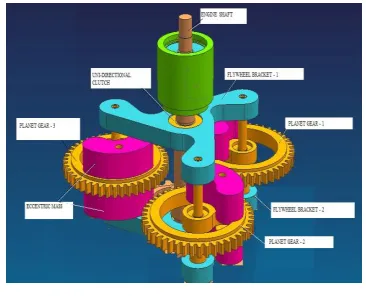
Fig. No.1 Inertia Augmentation Mechanism
Two gear wheel rotors are swiveling stored on a main rotor shaft. The main rotor shaft is for his part stored on the tax axle swiveling. The gear wheel rotors reach into the tax gear wheel and unreel around this.
On the gear wheel rotors mirror-symmetrically eccentric cam weights are appropriate to the tax axle. During a circulation of the rotors around the tax gear wheel move the eccentric cam weights on a certain course, which runs eccentrically to the tax axle. This course results from two rotations, which are engaged into one another. The eccentric cam weights turn around the axles of the gear wheel rotors and these turn around the tax axle.
Fig. No.2 3D Model of Compact Flywheel Using Inertia Augmentation Mechanisms
Thus test rig were design and developed table 1 shows the design specifications
Table 1.
Design Specification of Elements
Sr. No. Element Specification
1 Planet Gear Module 2 mm, Number of teeth is 44,
Addendum Diameter is 92 mm and Pitch Circle Diameter is 88 mm
2 Engine Shaft Diameter is 6.8 mm
3 Bearing Bearing Number 6003-2Z , 6002-2Z,
4 Gear Pin Diameter is 6 mm and length is 10 mm
5 Unidirectional
Clutch
Torque is 1.65786 x 10³ N.mm
6 Coupling Shaft Diameter are 24mm, 16mm, 36mm
7 Flywheel Shaft Length is 195 mm
8 Bearing of
Flywheel Shaft
Bearing Number 6005
[image:2.612.91.241.538.633.2]International Journal of Emerging Technology and Advanced Engineering
Website: www.ijetae.com (ISSN 2250-2459, ISO 9001:2008 Certified Journal, Volume 7, Issue 8, August 2017)
[image:3.612.51.289.135.270.2]261
Fig. No.3 Test Bed for Experimental PerformanceFigure 2 and 3 represents the assembly and details of the developed flywheel augmented technique. A test bed with engine mounted flywheel was developed for conducting trials at various loads. Test bed utilizes a two stroke petrol engine; table 2 represents specifications of the engine.
Table No.2
Specification of Two Stroke Petrol Engine
Sr. No. Parameter Specification
1 Make Crompton Greaves
2 Model IK-35
3 Bore Diameter 35 mm
4 Stroke 35 mm
5 Power 1.2 BHP
6 Speed 5500 RPM
7 Torque 1.76 Nm at 5000 RPM
8 Capacity 34 CC
9 Dry Weight 4.3 Kg
Compact flywheel was mounted with test bed and trials were conducted at the engine speed of 1300 rpm. Rope brake dynamometer was used for measurement of transmitted torque and power of the flywheel. With the use of dead weights load was varied from 1500 gm to 5000 gm. This ensures the complete range of engine power delivery. Speed was then noted to calculate the power and efficiency transmitted. Digital tachometer with a range of 0 to 10000 rpm and model LT DT-2234C was used for measurement of speed. Readings are then repeated for each load variation.
III. RESULTS AND DISCUSSION
Experiments were conducted with developed
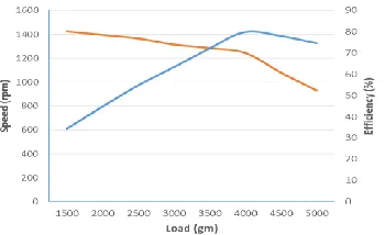
experimental setup. Load on the flywheel was varied from 1500 gm to 5000 gm. Load and input speed was measured and the power output from the flywheel was measured to determine the efficiency of flywheel. Fig. 4 represents the effect of variation of load on the output speed and efficiency of the flywheel. It is observed that with increase in load on flywheel speed decreases. As load increase from 1500 to 4000 gm speed decrease by 12%, however as load increases from 4000 to 5000 gm speed decrease by 25%. This is the major cause for increase in efficiency up to a load of 4000 gm and again it decreases by 7 to 8%. This can also be attributed to load carrying capacity of two stroke petrol engine.
IV. DEVELOPMENT OF ANFISPREDICTION MODEL
[image:3.612.360.535.572.679.2]The experimental data set was collected out of which 80% datasets were utilized as a training data and the remaining 20% data sets as a testing data. The fuzzy Inference System was trained with training data sets and training for 1000 epochs. To verify the accuracy of prediction other testing data sets were used. The training was conducted using Sugeno type fuzzy inference system with different rule, three membership function of each input parameter, hybrid of least square – gradient descent learning algorithm and linear output. The membership is categorized in low, medium and high for each input parameter. The analysis of experimental data was conducted on MATLAB work station. The data input to the ANFIS workbench of MATLAB was in the form of four columns. The first three columns were treated as input and the last column as output data for the training Fuzzy inference system (FIS). The experimental data is utilized to train FIS using bell shape, triangular and trapezoidal membership function.
International Journal of Emerging Technology and Advanced Engineering
Website: www.ijetae.com (ISSN 2250-2459, ISO 9001:2008 Certified Journal, Volume 7, Issue 8, August 2017)
[image:4.612.320.552.137.700.2]262
Fig. No.5 ANIS Model FIS StructureThe selected training data is loaded Adaptive neuro fuzzy inference tool box of MATLAB from the workspace. This training and testing data was loaded in MATLAB session window. FIS structure was generated with MATLAB Fig 5 represents the FIS structure.
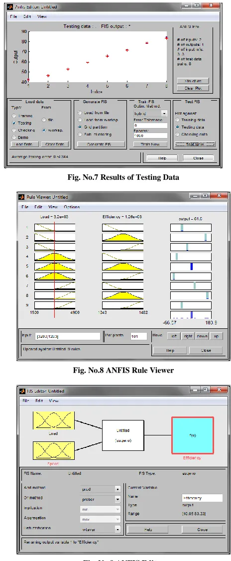
Gaussian membership function was selected and then training data was loaded. Total 1000 epochs were considered for training of the FIS. Fig 6 represents the training with ANFIS model. The observed error at 553 epochs was about 0.30353 only. Test data was then loaded from session window and the model was tested. Average testing error observed was only about 0.5033. Fig 7 shows the results of testing with ANFIS model. Fig 8 and 9 represents ANFIS Ruler Viewer and ANFIS Editor for the given input and output variables.
Fig. No.6 Training for 1000 Epochs
[image:4.612.55.287.137.332.2]Fig. No.7 Results of Testing Data
Fig. No.8 ANFIS Rule Viewer
[image:4.612.60.278.515.698.2]International Journal of Emerging Technology and Advanced Engineering
Website: www.ijetae.com (ISSN 2250-2459, ISO 9001:2008 Certified Journal, Volume 7, Issue 8, August 2017)
[image:5.612.47.283.305.503.2]263
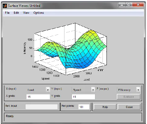
Fig. 10 shows the surface viewer for the developed model. It is observed that at minimum loading of the engine with increase in speed from 1100 to 1250 rpm efficiency was increased and observed as maximum 96% at a speed of 1250 rpm. However efficiency was decreased with further increase in speed. Efficiency was about 48% at a speed of 1400 rpm. At a load of 3000 gm similar behavior was observed, however the efficiency was quite lower than at a load of 2000gm. Predicted efficiency with ANFIS model was then compared with experimental values; good agreement was observed between the predicted and experimental value with an AVERAGE ERROR OF 9.043. Fig. 11 represents the agreement of predicted and experimental results.Fig. No.10 Surface plot for Effect of Load and Speed on Efficiency
Fig. No.11 Results of Experimental vs ANFIS Predicted
V. CONCLUSION
Experimental analysis was conducted for the inertia augmented flywheel. It was observed that with increase in load speed was decreased and the efficiency of the flywheel was increased. At a load of 4000 gm. Efficiency was maximum and observed as 79%. Prediction model was developed using ANFIS which has a good agreement with experimental data with an error band of 9% only.
REFERENCES
[1] S S Ratan, ―Theory of Machines‖, Third Edition, Tata McGraw Hill Education Private Limited, ISBN-13:978-0-07-014477-4, Page No. 461 to 470.
[2] Fridericy, Palos Verdes Estates (1980), Multi-Rim Flywheel Attachment, United States Patent, and Patent Number: 4,186,623, Application Number 892,587.
[3] R J Haley, J P Kajs, R C Thompson, J H Beno (1998), Design and Testing of a Flywheel Battery for a Transit Bus, Society of Automobile Engineers, 1999-01-1159.
[4] Park, Dong-Hoon, Suwon-Si, Kyunggi-Do (KR), (2000), Dual Mass Flywheel for Automobile Vehicle, European Patent Application, and Patent Number EP 1 046 834 A2, Application Number: 00105556-5. [5] Alastair John Young, Kenilworth, (2000), Twin Mass Flywheel, United States Patent, Patent Number 6 029 539, Application Number: 09/125 340.
[6] Richard Benito Fradella, San Juan Capistrano (2004), Robust Minimal-Loss Flywheel Systems, United States Patents, Patent Number: US 6 794 777 B1, Application Number: 10/739 119. [7] Bjorn Bolund, Hans Bernhoff, Mats Leijon (2005), Flywheel Energy
and Power Storage System, Science Direct, 11 (2007) 235 – 258. [8] Ulf Schaper, Oliver Sawodny, Tobias Mahl and Uli Blessing (2009),
Modeling and Torque Estimation of an Automotive Dual Mass Flywheel, American Control Conference, Hyatt Regency Riverfront, st Louis, Mo, USA, June 10-12, 2009, WeB16.6.
[9] Walter J Ortmann, Saline (2011), Controlling Torque in a Flywheel Power Train, United States Patent Application Publication, Publication Number: US 2011/0071000 A1, Application Number: 12/562 187.
[image:5.612.52.285.533.685.2]