International Journal of Emerging Technology and Advanced Engineering
Website: www.ijetae.com (ISSN 2250-2459, ISO 9001:2008 Certified Journal, Volume 9, Issue 3, March 2019)
191
Rectangular Slot Patch Antenna Design for S-Band
Applications
Pendli Pradeep
1, KNS Ganesh
21,2
Assistant Professor, ECE Dept, SNIST Abstract— Small size Patch antenna is designed in this
paper. Rectangular shape patch is used for radiation. It is a low profile, less cost and weightless radiating rectangular shape patch antenna that are capable to achieve greater performance over wireless communication systems operating at S-band frequency. This microstrip rectangular patch antenna is having Rogers RT/duroid 5880(tm) dielectric substrate. It is simulated after design using ansys HFSS software is used, and optimization is done to get the improved result using a rectangular slot on radiating patch. The center frequency is chosen for this antenna is 3.30 GHz. Which is useful for WiMAX applications, GPS applications and many in S-band applications. This Designed rectangle patch shape antenna have a simple rectangular slot. This simple RMPA is designed with 35mm*25mm with substrate thickness 1.6mm. Microstrip patch antennas are commonly needed because these are having many advantages like as low volume, and low fabrication cost. The designed final antenna performance is measured like VSWR, bandwidth, gain, surface current density, return loss, and input impedance of antenna. This proposed rectangle slot antenna has given good results.
Keywords—HFSS, MSPA, CMSPA, S-BAND
I. INTRODUCTION
Transmission of signals or energy or information for the purpose of communication i.e transmission of information from one place to other place over a long distance is assisted by telecommunication. In present days, wireless and telecommunication systems generally involved in advanced electronic transmitters and receivers such as television, mobile, telephone, radio system or computer system. Satellite, telecommunication and wireless mobile communication system applications are generally involved with microstrip patch antennas because of their attracted features like light weight, small size, low cost production, low profile, simple fabrication steps and simple integration with their components [1]. Existence of Microstrip patch antenna are identified around in 1950s. But during this time very less work was done on microstrip patch antennas.
Until 1970s, these microstrip antennas became quite popular as the advantages of these microstrip patch antennas existence were well known to the researchers.[2] Mobile phone is need a very small size antenna which can easily be fit inside the body of cellular mobile phone, although tried always continuing increasing the gain, polarization, bandwidth, and directivity of these antennas by making it either truncated, etched, slotted or grounded plane of these microstrip antennas are modified. A truncated RMPA is designed to improve the performance of defected RMPA for GSM application [3]. In this way rectangle slot is etched on this designed microstrip rectangle patch antenna to meet better results. The advantages of these antennas were known to every researcher. Patch antennas find several applications in wireless communication, communication systems and Worldwide Interoperability for Microwave Access (Wi-MAX), Global Positioning system (GPS), biomedical diagnosis, RFID etc. [1]-[3]. Recent days need wireless communication with better results in various applications. Moreover, many numbers of wireless users are increasing every day and due to that spectrum availability is shortage problem is occurred. In coming generation communication networks like as 5G and its advanced technology will use millimeter-wave frequencies [4].
International Journal of Emerging Technology and Advanced Engineering
Website: www.ijetae.com (ISSN 2250-2459, ISO 9001:2008 Certified Journal, Volume 9, Issue 3, March 2019)
[image:2.612.66.288.143.231.2]192
Figure 1 Microstrip Antenna fringing fields
Microstrip patch antennas are initially radiate because of their fringing fields existence between the radiating patch edge and the grounded plane. Dielectric substrate is placed between patch and ground. The microstrip patch antenna can be fed by several of methods. Every method has their own advantages and disadvantages. These feed methods are classified into two different categories- non-contacting and contacting methods. In the first method, EM filed coupling to be done to transfer power from microstrip line and radiating patch these types are includes aperture feeding and proximity feeding. In the second method, the RF power is directly given to the radiating patch using a microstrip line or probe feed [6]..
II. DESIGNED ANTENNA LAYOUT AND SPECIFICATIONS
A rectangular microstrip antenna is very useful and commonly used for a UWB system communication applications as well as S-band applications. The designed antenna’s center frequency is3.3 GHz. The radiating patch does not contain any slots. The proposed rectangular shape patch antenna has been designed using a dielectric substrate material Rogers RT/duroid with dielectric constant is equal to Ꜫr= 2.2 and height of substrate is taken as (h) = 1.6 mm.
Figure 2 Designed Rectangular Patch antenna
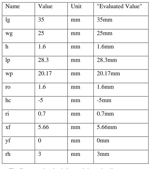
The proposed antenna parameter values are mentioned in the below table.
TABLEI DESIGN PARAMETERS
Name Value Unit "Evaluated Value"
lg 35 mm 35mm
wg 25 mm 25mm
h 1.6 mm 1.6mm
lp 28.3 mm 28.3mm
wp 20.17 mm 20.17mm
ro 1.6 mm 1.6mm
hc -5 mm -5mm
ri 0.7 mm 0.7mm
xf 5.66 mm 5.66mm
yf 0 mm 0mm
rh 3 mm 3mm
The Rectangular slot is located these details
The Position of rectangular slot is located at "-px, py, h" with values "-8mm , 5mm , 1.6mm" and Axis is Z with XSize is -2mm and YSize is -8mm.
[image:2.612.320.567.156.433.2] [image:2.612.51.286.528.656.2]International Journal of Emerging Technology and Advanced Engineering
Website: www.ijetae.com (ISSN 2250-2459, ISO 9001:2008 Certified Journal, Volume 9, Issue 3, March 2019)
[image:3.612.56.283.130.259.2]193
Figure 3 Designed Rectangular Slot Patch antenna
From the Figure 5 it can be understood that Rectangular slot is used on patch because of that the proposed and designed antenna is giving best results as compared to same antenna without slot.
III. RESULTS AND DISCUSSION
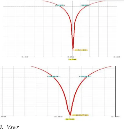
These results are obtained for Simple patch antenna with a slot and without slot. Using a rectangle slot on a Rectangular antenna is given good return loss and VSWR values. It shows the performance of an antenna.
TABLEII
RESULTS ANALYSIS WITHOUT SLOT AND WITH SLOT ON PATCH
Parame ter
Operati ng frequen
cy [GHz]
Retu rn loss
Gain[d Bi]
VSW R
Impeda nce
Withou t Slot
3.30
-29.70
5 1.07 47.26+i2 .01
With Slot
3.26
-54.13
5 1
49.90-i0.17
A. Return Loss
Return Loss is the loss of power. We can measure this in the form of energy reflected by the mismatch load in a lossy transmission line. i.e the load impedance is not equal to characteristics impedance. Reflection coefficient is very useful parameter. Which is the important factor and measures return loss. Sometimes it referred to as standing wave ratio (SWR). Return loss can represented as, RL = -20 log [K] here K is Reflection Coefficient.
This designed simple microstrip Rectangle shape patch antenna is given return loss -29.70 dB at the frequency 3.3 GHz with bandwidth 140 MHz and the same antenna with rectangular slot is giving return loss -54.13 dB at resonant frequency 3.26 with sane bandwidth.
B. Vswr
[image:3.612.327.540.198.420.2]International Journal of Emerging Technology and Advanced Engineering
Website: www.ijetae.com (ISSN 2250-2459, ISO 9001:2008 Certified Journal, Volume 9, Issue 3, March 2019)
194
C. Input ImpedanceThe below figure shows input impedance of an antenna with real value 47.56 ohms and inductive value i2.01 ohms. if input impedance of an antenna real part is 50 ohms and imaginary part is zero then reflected wave is zero it means complete transmission. So, using impedance matching technique it can be possible to get 50ohm value. Rectangular slot is included in simple microstrip patch antenna get real part of impedance close 50 ohms but in the design, it is giving close value 49.90 ohms and imaginary value is capacitive value -i0.17 ohms.
D. Surface Current Density
International Journal of Emerging Technology and Advanced Engineering
Website: www.ijetae.com (ISSN 2250-2459, ISO 9001:2008 Certified Journal, Volume 9, Issue 3, March 2019)
195
IV. CONCLUSION
In this paper entire work is used to present a simple microstrip patch antenna to achieve negligible return loss and useful bandwidth for Wi-MAX frequency range applications and s band applications. The return loss is minimized by suitable impedance matching techniques. This antenna is fed with coaxial feeding technique to provide impedance matching and the placed is located. This microstrip patch antenna designed with dielectric substrate Rogers RT/duroid 5880(tm), Simple RMPA is designed with 35mm*25mm with substrate thickness 1. 6mm. The center frequency of Rectangular patch shape antenna is 3. 30 GHz. It gives return loss -29.70dB. To improve this return loss a Rectangle shape slot is used on radiating patch. This modified antenna is given return loss -54.13dB because of impedance match with slot. The performance of the designed patch antenna with and without slots were analyzed and simulated to get results like bandwidth, return loss, surface current density in terms of magnitude and vector analysis and these results are improved with simple rectangular slot on patch antenna.
REFERENCES
[1] A.S.M. Bakibillah1, Md. Sakhawath Hossain2, Ivy Saha Roy3 “Design of a micro strip patch antenna to minimize return loss for WI-MAX application” IJARCCE Vol. 3, Issue 12, December 2014.
[2] Navreet Kaur, Shivani Malhotra, “A Review On Significance Of Design Parameters Of Microstrip Patch Antennas” 978-1-5090-0893-3 2016 IEEE.
[3] Hemant Kumar Gupta, Bhupesh Gautem, Poonam Sinha,Abha Soni, “Design of Very Low Return Loss, Rectangular Microstrip Patch Antenna for Cellular and Mobile Communication” International Journal of Electronics and Electrical Engineering Vol. 1, Manuscript received June 1, 2012; revised August 4, 2013. [4] Youssef El Gholb, Mohamed El Bakkali, Ahmed Mounsef, Ikram
Tabakh,Najiba El Amrani El Idrissi “A 9-shaped Antenna for 5G Applications” 978-1-5386-2123-3 2017 IEEE.
[5] Vijayalaxmi S W, Dr.A Sreenivasan “Design and Simulation Of Ircular Microstrip Patch Antenna” (ICIMIA 2017) 978-1-5090-5960-7 201978-1-5090-5960-7 IEEE.
[6] Alak Majumder “Rectangular Microstrip Patch Antenna Using Coaxial Probe Feeding Technique to Operate in S-Band” (IJETT) - Volume4Issue4- April 2013.
[7] Muhammad Rasheduzzaman1, Md Muhtasim Billah3 “Performance analysis of a Hexagonal Microstrip Antenna for S-band spectrum using hfss” 978-1-4673-8688-3 2015 IEEE.
[8] Houda Werfelli, Khaoula Tayari, Mondher Chaoui, Mongi Lahiani, Hamadi Ghariani “Design of Rectangular Microstrip Patch Antenna 2nd International Conference on Advanced Technologies for Signal and Image Processing” - ATSIP'2016 March 21-24, 2016, Monastir, Tunisia 978-1-4673-8526-8 2016 IEEE.