Towards Interference Alignment for Distributed
Large-Scale MIMO Hardware Architecture and
Implementation
Savitri Galih1,*, Mohammed El-Absi2, Thomas Kaiser2
1Widyatama University, Cikutra 204A, Bandung, Indonesia
2Institute of Digital Signal Processing, University of Duisburg-Essen, Duisburg, Germany
Copyright©2019 by authors, all rights reserved. Authors agree that this article remains permanently open access under the terms of the Creative Commons Attribution License 4.0 International License
Abstract
Massive MIMO or Large Scale MIMO is apromising solution for achieving superior data rates in 5G communication systems. However it has limitation in term of scalability and coverage for users that has highly spatial separation. Distributed massive MIMO is expected to enhance these drawbacks. One main problem arises in this scheme is the MIMO interference channel conditon that can be coped by interference alignment algorithm. The main consideration for interference alignment algorithm in distributed Massive MIMO is to achieve low complexity precoding to eliminate interference channel condition and to design efficient hardware architecture for its implementation. Previous research regarding IA for Distributed Massive MIMO indicates that the complexity issues is still not widely discussed. This paper proposed the low complexity IA scheme for large scale MIMO system based on limited interferer and the implementation of low cost interference alignment and wireless synchronization for distributed MIMO using software defined radio hardware. From the simulation result it is shown that limited interferer IA algorithm achieve acceptable BER performance ,i.e. in order of 10-3. The hardware implementation of the IA precoding matrix computation is also discussed and base on the experiment it is show that the proposed algorithm and architecture achieved higher hardware performance compared to the linear IA.
Keywords
Distributed Massive MIMO, InterferenceAlignment, FPGA
1. Introduction
Delivering superior data rates without sacrifying the quality of service is the key task for the wireless communication business. This task is well suited to the objectives of the 5G communication systems for achieving
higher data rates. However, with the enormous growth of mobile data traffic due to the high number of mobile video streaming and mobile internet operation, it is challenging to manage the resulting condition, i.e. limited wireless spectrum and resources. One of the recommended solutions of this problem is Massive MIMO. Extensive research has been carried out since the first launch of Large Scale MIMO (Massive MIMO) to attain much greater scale of MIMO advantages i.e (higher energy efficiency, higher data rate , higher reliability, and lower interference) (Larsson et al., 2014). Massive MIMO denotes the large number antenna fixed connected at base station. Despite of the advantages, massive MIMO has limitation in term of scalability and spatial diversity or coverage for highly spread user. To enhance these drawbacks distributed Massive MIMO possibly will be a supreme way out. Distributed MIMO with physically distributed transmitters and receivers lead to the MIMO interference channel condition. Each firm one to one association between multiple transmitters and receivers will produce interferences between each transmission link. Recent research activities regarding analysis of the MIMO interference channel in topics of interference alignment has received significant attention among researchers. Interference Alignment is basically instituted by precoding methods for the MIMO interference channel (Yang and Hanzo, 2015). The alignment process of the interference essentially is transmit schemes that are constructed to make the interfering signals from transmitter is as low as possible (Schmidt et al., 2010; Cadambe and Jafar, 2008).
condition and to design accurate synchronization to enable coherent transmission.
Several recent studies in the topics of IA and/or precoding technique for Large scale MIMO system (Larsson et al., 2014; Shepard et al., 2012; Cerato and Viterbo, 2009; Suzuki et al., 2012; Marzeta, 2010) hardly emphasize the issue of computational complexity of the precoding/IA scheme. This paper will propose the low complexity IA scheme for large scale MIMO system based on limited interferer. We limit the interferer that contributes to the preceding matrix to reduce the complexity.
Moreover the implementation of low cost interference alignment for distributed massive MIMO using Xilinx ISE Dedsign platform is also discussed.
2. Review of Precoding Scheme for
Large Scale MIMO System
Precoding process, which employ an antenna array to lead transmitted signal directly to the intended receiver antenna, is the core of Multi User MIMO. Precise Channel State Information is required for the precoding design in MU MIMO (Rogalin et al., 2014).
Since the beginning of large scale MIMO system, which has obtained great interest recently due to the its numerous advantages in term of capacity, interference robustness, e.t.c, there are some studies discussed about precoding process in this massive MIMO system. However there are some issue regarding the computational complexity of IA and precoding schemes required for the system. It required excessive process to compute large scale precoding matrix in large scale MIMO system
Since distributed MIMO with its interference channel nature will be mainly discussed, in this work we focus primarily on low complexity interference alignment technique for large scale condition.
There has been large amount of work on precoding and IA scheme for large scale antenna system. By exploiting polynomial expansion for rewriting the matrix inversion then truncate it, (Mueller et al., 2016) proposed low complexity linear precoding that can be implemented in large scale system. Despite its function to eliminate precoding matrix precomputation and reduce transmitted symbol delay, the truncated polynomial expansion precoding implementation for Interference alignment need different approach that vastly difficult. For interference networks (Chen and Lau, 2014) developed two tier precoding with subspace alignment motivated by the clustering behavior of the user terminal. This scheme is implemented for classic (undistributed) massive MIMO with large number of antennas is placed in one centered place by considering one ring local scattering model. With such local condition requirement, this scheme’s
performance and feasibility is still unproved for
implementation in distributed large scale MIMO system. [16] proposed large scale system precoding algorithm by continually optimize receiving and transmitting precoding vectors iteratively based on Interference Alignment criterion and achieve significant performance gains. Despite its high performance result, this algorithm has not addressed high complexity issue which raise substantial obstacle in hardware implementation process.
3. Interference Alignment with Limited
Interferer
3.1. System Model
Let us consider the large scale (16 rank and 32 rank) distributed MIMO interference channel with K user and N Number of antennas per user at each transmitter and receiver (Figure 1).
The received signal at the kth receiver at time t is represented as follows :
) ( 2
2 1
1() () () () ... () ()
)
( k k kK k kt
k t H t X t H t X t H t X t Z
Y = + + + +
(1) Where, k∈
{
1,2,...,K}
is the user index, Yk(t) and) (t
Xk is the received signal at the kth receiver and transmitted signal from the kth transmitter respectively,
) (t
Hkj is the frequency domain channel coefficient from
transmitter j to receiver k at time t and Zk(t)is the additive white Gaussian noise (AWGN) term at receiver k. Some assumption is taken in the system i.e : Channel State Information (CSI) at each node is perfectly known, all noise terms are independent identically distributed (i.i.d) zero mean complex Gaussian.
3.2. Linear Interference Alignment Review
(Cadambe et al., 2008) discussed linear interference alignment algorithm in K-user MIMO interference channel with N receive and transmit antenna by employing symbol extension of the channel. In this condition, transmitted message is encoded by multiplication with IA precoding matrix V and the received signal at the ith receiver can be written as :
( )
( ) ( )
( ) ( )
( ) ( )
( )
1 1 1 2 2 2
i i i
ij j j i
t t t t t
t t t
= + +
+ +
Y H V X H V X
H V X Z
(2)
where Hij is N x N frequency domain channel matrix
between ith receiver and jth transmitter, Xj is symbol that is
transmitted from jth node, and Zi is zero mean AWGN
vector at receiver i.
transmitted signal the received signal is decoded by suppression matrix U given by (El-Absi et al., 2012):
[
]
(
ij j)
i null H V
U = (3)
The linear IA algorithm carries out zero forcing to all undesired precoding vector at the receiver to eliminate interference. The interference vectors are linearly independent with the desired signal space.
3.3. Proposed IA
In this research we aim to achieve low complexity Interference Alignment algorithm by proposing the limited interferer Interference Alignment for K-User MIMO. 3.3.1. Large Scale K-User SISO Interference Channel
For Large scale scenario, if the (Cadambe et al., 2008) Interference Alignment algorithm is used to determine V1
will require high matrix dimension,i.e if K = 32 and n = 1, the V1 matrix will consist of 2N=2(32-1)(32-2)-1. This condition lead to high complexity computation required for the IA process.
We modified IA precoding equation in 1st receiver V1
from (Cadambe et al., 2008) in order to reduce the complexity in large scale system by limiting the maximum index of the equation. The cellular network phenomenon stated that the far-away interference signal power is highly decrease due to the distance between the non-adjacent user. Therefore we can limit the range of the IA precoding equation to the number of significant interferer instead of the number of the user.
To determine the number of the significant interferer, we choose it based on modification of the theorem that characterize the feasibility of interference alignment stated below (Bresler et al., 2011).
1 2 + ≤ L N
d (4) where d= degree of freedom, N = Number of antenna per user and L= number of interferer. For N = 1 and d =1, we get L= 3.
Base on the above assumption, for K user Single input single output system, we limit the dimension of the interference alignment precoding equation’s upper bond index from the number of user to the number of limited interferer(L) as shown in equation below:
[ ]
( )
{
}
∈ ∀ =
∏
nV mk
l m m l mk .., 2 , 1 , 0 : , , 1 α α w
T (5)
where m,l∈
{
2,3,..,L}
,m≠l,(
m,k) ( )
≠ 2,3 [ ] ( )j ij i i
j H HS
T 1 1
−
= (6)
( )
( )
211 23 13 1
1 H H H
H
Sj = i − − (7)
3.1.2. Large Scale K-User MIMO Interference Channels
In the large scale K-User MIMO interference channels systems, to decode the datastreams from the received signal vector, each undesired precoding vector space must have full intersection as follows:
At Receiver 1:
) ( )
( )
(H12V2 span H13V3 spanH1KVK
span = ==
At Receiver 2:
) (
) ( )
(H21V1 span H23V3 span H2KVK
span = ==
At Receiver 3:
) ( )
( )
(H31V1 spanH32V2 span H3KVK
span = == (8)
At Receiver K:
) (
) ( )
(HK1V1 =span HK2V2 = =span HKK−1VK−1
span
The above equations can be restricted with the Interference Alignment method described as
) ( )
( )
(H12V2 span H13V3 span H1KVK
span = = (9)
K KV H V H V
H21 1= 23 3== 2
K KV H V H V
H31 1= 32 2 == 3 (10)
K K K K
KV H V H V
H 1 1= 2 2== ( −1)
Base on [Cadambe] Vi, i=2,3,...,K determined by
( )
31 11 32
2 H H V
V = −
( )
21 1 1 233 H H V
V = − (11)
(
)
1 11 ) 1
( H V
H
VK K K K
− −
=
Base on equation (20a) and the assumption that the limited interferer is equal to 3 as in equation (4), we use same factor H13V13 to determine Vi, i =4,5,..K below.
( )
13 3 1 144 H H V
V = −
( )
13 3 1 155 H H V
V = − (12)
(
)
13 3 11 H V
H
VK K
−
=
for determining V1, we use the equation below.
( )
1 1)(V span EV
span = (13) where
( )
( )
( )
1 2123 13 1 12 32 1
31 H H H H H
H
E= − − −
[ ]
E
eig
V
1=
3.1.3. Computational Complexity Discussion
With an increased number of antennas in large scale MIMO scheme, Interfence Alignment process has to examine larger Interference Alignment precoding matrix (V).
In this section, the computational complexity of linear Interference Alignment algorithm from (Cadambe et al., 2008) and proposed IA is compared. The complexity is computed based on the number of multiplication required to compute Interference Alignment precoding matrix (V).
By using same factor (h13.v3) for Vi (i=4 to K) we can reduce computional complexity since the factor only compute once and store it to memory and is read every Vi (i=4 to K) computation, instead of compute it K – 3 times as in eq.(12)
Figure 1. Computational Complexity
For each i, i= 1 to K where K is the number of user with each M antenna, it require one M rank matrix inversion and two M rank matrix multiplication. The computation will highly increase for large scale condition.
In Fig. 1 and table 1 computational complexity comparison between Linear IA from (Cadambe et al., 2008) and proposed IA is shown.
Table 1. Computational Complexity
IA Algorithm Multiplication #
Linear IA [Cadambe] K.(M2+M)
Proposed Algorithm (M2+M)
4. Simulation Result
In this section, we observe the bit error rate (BER) performance of proposed limited interference based IA algorithm in the large scale Distributed MIMO system and the effect of costas loop synchronization in this larga scale system. In our simulation, we set up two scenario 16 and 32 distributed transmitters, each has 2 antennas and we also consider the case that the number of user (K) is 16 and 32. An i.i.d complex Gaussian distribution has built the channel matrix Hij with zero mean and unit variance. For all the simulation we use QPSK modulation.
[image:4.595.74.275.294.418.2]The simulation contain two part, i.e one dedicated Masternode and 32 users distributed MIMO system. The Master node sends a reference signal to transmitters. By using this reference signal, the transmitters can estimate the offsets of each distributed transmitter. Costas loop then synchronize the signal by compensating the offsets. After synchronization process takes place, the transmitters carry out proposed limited interferer based IA algorithms so that the transmitted signal can be retrieved without error due to interference in the desired receiver.
Table 2. BER Performance Difference after Sync
Number of User BER Performance Difference (dB)
16 10 dB
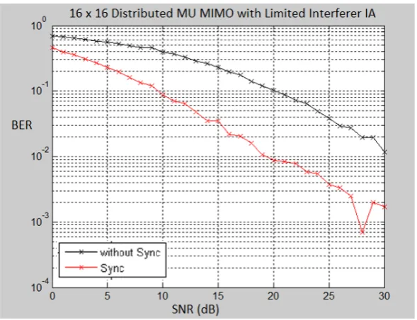
[image:4.595.151.446.527.753.2]Figure 2. BER performance of 16 x16 Distributed MU MIMO with Limited Interferer IA
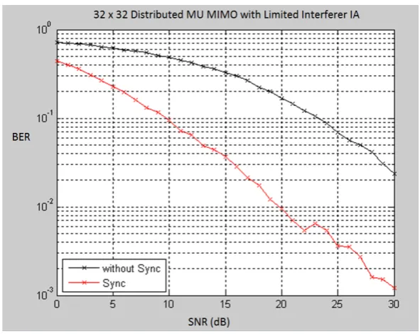
Figure 3. BER performance of 32 x 32 Distributed MU MIMO with Limited Interferer IA
Figure 2 and 3 presents the simulation of the synchronized and unsynchronized 16 and 32 users Distributed MIMO which employ proposed limited interferer IA algorithm respectively. In this plot we can observe that the distributed synchronization algorithm increase the BER performance by 10 dB at axis (BER) value 10-1 for 16 users and 13 dB at BER value 10-1 for 32 users. We can conclude that the effect of the distributed synchronization in larger scale of distributed MIMO is higher than the less scale. The increasing of performance in larger scale distributed MIMO is due to higher number offset experienced by all transmitters that is compensated by the synchronization process.
Moreover, we can also observe the performance of the proposed IA algorithm. The simulation results show that the BER performance of the proposed limited interferer IA algorithm achieve acceptable BER performance (10-3).
5. Hardware Implementation
In this section we discuss hardware implementation of limited interferer IA and the linear IA using VLSI technology.
5.1 Hardware Architecture
This section explains two architectures for calculating precoding matrix of IA in distributed large scale MIMO system. The first architecture implements the linear IA approach from reference (Cadambe et al., 2008) and the next architecture is mapped for proposed limited interferer method. The explanation of the two architecture enables us to compare the hardware performance of the two approaches.
Matrix Multiplier Unit RAM A
RAM B
X +
[image:6.595.99.497.77.380.2]Acc RAM C Controller
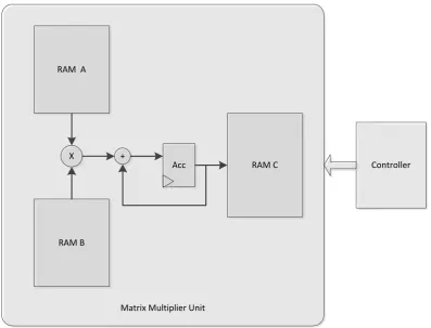
Figure 4. Architecture of Limited Interferer IA Precoding Matrix Multiplication
The architecture of limited interferer (based on eq 12) is depicted in fig 4. The d the limited interferer IA only have one matrix multiplication module. On the other hand, the linear IA arcchitecture have two matrix multiplication modules. The proposed IA can reduce the number of matrix multiplication since it has preprocessing unit that compute another matrix multiplication only once, i.e. computes H13.V3 one time.
We used Xilinx ISE 14.7 and Xilinx Core Generator for designing the architecture, VHDL synthesis and place-and-route. The FPGA device for implementation target is Spartan 6 family XC6SLX4 device.
a. Architecture of Linear Interference Alignment
In Linear Interference Algorithm from[Cadambe] the interferer for every antenna index must be considered. Precoding Matrix (Vi, i= 2 to K) is determined by equation
11. The hardware architecture contain two matrix multiplier module and five memories. First Matrix Multiplier calculate Hi1.V1 (i=2 to K). and the second Matrix Multiplier calculate Vi (i= 2 to K) Both Matrix Multiplier must compute K-1 times to determine the precoding matrices.
b. Architecture of Limited Interferer Interference Alignment
The proposed hardware architecture (figure 4) consists of three memories and one Matrix Multiplier module. The Matrix Multiplier module performs calculation to retrieve
main IA precoding matrix in equation (12). For the Limited Interferer IA precoding matrix computation, we also need the inverse of channel coefficient matrix. The first input RAM stores the inverse of channel coefficient (Hij-1 ) and the second input RAM store the H13V13 calculation result. We assumed that channel coefficient matrix is already known and has been pre computed.
In order to achieve low complexity hardware implementation, we propose memory shared architecture that reduce the matrix multiplication computation. The number of the matrix multiplication process is reduce by precomputing factor in eq (12) one time and store it to one memory (RAM B). Hence, RAM B operates as shared memory accessed during matrix multiplication computation for every precoding vector space index. Since the H13V13 multiplication doesn’t have to calculate everytime we compute each precoding matrix (V4to VK), the computational complexity is highly reduced.
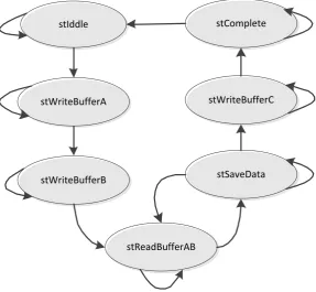
5.2. Finite State Machine (FSM)
To carry out the hardware implementation, the computation proces is partitioned into a number of state. The FSM diagram of proposed algorithm is depicted in figure 5
a. Linear IA State
1)State stIdle: No activity, go to state stWriteBufferA01 if signal write enable and buffer select = 1
2)State stWriteBufferA01: Write data Hk1 to RAM
A01, go to state stWriteBufferA02 when counter reach 1024 ( RAM size)
3)State stWriteBufferA02: Write data Vk to RAM A02 go to state stReadBufferA0 when counter reach 1024 ( RAM size)
4)State stReadBufferA0: read data Hk1 and Vk for multiplying process, go to state stSaveDataA when counter A01 and counter A02 reach 32 (number of user/antenna).
5)State stSaveDataA: ready to save the matrix
multiplying result
6)stWriteBufferA: write the matrix multiplying result to RAM A, go to state stWriteBufferB when counter reach 1024 (RAM size)
7)stWriteBufferB: write data H(K-1)K to RAM B, go to state stWriteBufferB when counter reach 1024 (RAM size)
8)stReadBufferAB: read data Hk1 and Vk multiplying result and H(K-1)K for second multiplying process, go to state stSaveData when counter A and counter B reach 32 (number of user/antenna).
9)stSaveData: ready to save the second matrix
multiplying result
10) stWriteBufferC: write the second matrix
multiplying result to RAM C, go to state
stComplete when counter reach 1024 (RAM size)
11) stComplete: k-index Precoding Matrix is ready,
go to stIdle.
b. Limited Interferer State
The state of the Linear IA algorithme are listed in the following
1) State stIdle : No activity, go to state
stWriteBufferA01 if signal write enable and
buffer select = 1
2) stWriteBufferA : write the precomputed H13 and V3 to RAM A, go to state stWriteBufferB when counter reach 1024 (RAM size)
3) stWriteBufferB : write data H1k to RAM B, go to state stWriteBufferB when counter reach 1024 (RAM size)
4) stReadBufferAB : read data Hk1 and Vk
multiplying result and H(K-1)K for second multiplying process, go to state stSaveData when counter A and counter B reach 32 (number of user/antenna).
5) stSaveData: ready to save the second matrix
multiplying result
6) stWriteBufferC : write the second matrix
multiplying result to RAM C, go to state
stComplete when counter reach 1024 (RAM
size)
stComplete : k-index Precoding Matrix is ready, go to stIdle.
stIddle
stWriteBufferA
stWriteBufferB
stReadBufferAB
stSaveData stWriteBufferC
stComplete
[image:7.595.154.442.452.717.2]5.3. Hardware Implementation Result
The design and development used Xilinx ISE 14.7 for VHDL synthesis and post place and route simulations. Both linear and limited interferer are implemented on Xilinx Spartan 6 FPGA. We compare the the maximum frequency and hardware resource usage of the main IA precoding matrix in two algorithms. Based on the architecture described in section 4.1, the main precoding matrix calculation is mapped as a customized hardware units on FPGA.
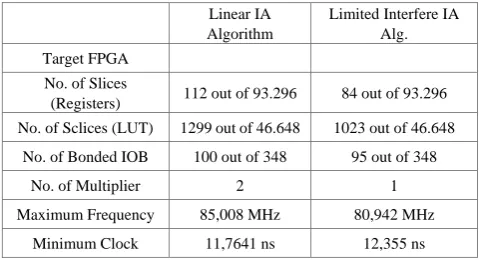
Table 3 summarizes the comparison of the post place and route frequency and the FPGA resource utilization for 32 x 32 MIMO System between linear IA and proposed Limited Interferer IA. The Result show that the Linear IA Algorithm utilizes more multipliers, more FPGA Slices and more memory than Limited Interferer IA Algorithm, due to the Linear IA algorithm contains more matrix multiplication process.
The number slice of registers in table 3basically is used as flip flops representing finite state machine. Since Since Linear IA algorithm has more states than limited interferer IA, it uses more flip flops. Limited interferer IA reduced the number of slice register by 25 %. The number of slice LUTs can be acquired from the accumulation of the slice use as Logic (Arithmatic Logic Function), the number of slice used as memory and the number of slice used exclusively as route-thrus (routing paths between slices). The greatest part that contributes to the number of Slice LUTs in linear IA is the number used as memory, since it has more dual port RAM than proposed limited interferer IA. From the table, ot is shown that the number of slice LUTs is reduced by 21 %.
Table 3. FPGA Resource Usage for Linear IA and Limited interferer IA
Linear IA Algorithm
Limited Interfere IA Alg. Target FPGA
No. of Slices
(Registers) 112 out of 93.296 84 out of 93.296 No. of Sclices (LUT) 1299 out of 46.648 1023 out of 46.648
No. of Bonded IOB 100 out of 348 95 out of 348
No. of Multiplier 2 1
Maximum Frequency 85,008 MHz 80,942 MHz
Minimum Clock 11,7641 ns 12,355 ns
The second last row is the maximum frequency retrieved by the synthesis tool. It can be observed that Limited Interferer IA achieve lower maximum frequency by 4%.
Next hardware performance evaluation is carry out by estimating power consumption and area of the FPGA Implementation. The power consumption is estimated using the XPower Analyzer tool included in ISE. The power utilized by all components is accumulated using the capacitance model of the target device and the specific switching information (toggle rates, signal rates, and frequency information) to calculate the power consumption
estimation.
The computation rate for IA algorithm especially for precoding matrix calculation with N receive and transmit antennas is defined by (Huang et al., 2008).
state avg
n
clk
f
N
C
.
.
max=
[image:9.595.54.294.493.623.2]where fmaxis frequency of the system in Megahertz, nstate is number of state and clkavgis average number of clock cycle per state with bit per dimension is assumed equal to 1.
Table 4. Computation rate for Linear IA and Limited interferer IA
Linear IA Limited Interferer IA
Transmit/Receive Antennas 32 32
System Frequency 85 MHz 80 MHz
Number of State 11 7
Average Clock Cycle per State 4,162 4,623
Computation Rate 53,484
Mbps 87,869 Mbps
The simulation result exhibit that the average computation time per state is 4,623 clock cycle for Linear IA and 4,162 cycle for limited interferer IA. The computation rate of the two algorithm is given table 4. It is showed that the Limited Interferer IA algorithm is 1,64 times faster than Linear IA algorithm.
6. Conclusions
In this paper, we present the limited interferer based Interference Alignment algorithm and its precoding matrix system architecture and implementation for large scale distributed MIMO. In order to reduce the precoding matrix for large scale MIMO scenario, instead of use the user index to build the matrix, we limit it to the number of interferer that calculate by degree of freedom equation. Through the simulation result, it can be observed that the proposed limited interferer IA algorithm achieve acceptable BER performance.
We apply memory shared architecture to reduce the matrix multiplication computation since the shared memory store the precomputing factor one time so the matrix multiplication doesn’t need to carry out every time we calculate the precoding matrix.
The system is prototyped on a Xilinx XC6SLX4-2-CSG75T device. It is showed that the Limited Interferer Algorithm has lower hardware complexity and has 1,64 times faster than Linear IA and use 21 % fewer FPGA LUT slices.
Part of this work has been published in a preliminary form in CEEC 2015 (Galih et al., 2015)
REFERENCES
B. Cerato and E. Viterbo, “Hardware implementation of [1]
low-complexity detector for large MIMO,” in Proc. IEEE ISCAS'2009, pp. 593-596, Taipei, May 2009.
Bresler, G., Cartwright, D., Tse, D.: Feasibility of [2]
Interference Alignment for the MIMO Interference Channel: The Symmetric square case . In IEEE Information Theory Workshop (ITW), 2011, pp. 47-451.
C. Shepard, H. Yu, N. Anand, L. E. Li, T. L. Marzetta, R. [3]
Yang, and L. Zhong, “Argos: Practical Many-Antenna Base Stations,” in Proc. ACM Int. Conf. Mobile Computing and Networking (MobiCom), Aug. 2012
Cadambe ,V.R., Jafar S.A.: Interference Alignment and [4]
Degrees of Freedom of the K-User Interference Channel. IEEE Transactions on Information Theory, pp.3425-3441 (2008)
Chen, J., Lau, V.K.N.: Two-Tier Precoding for FDD [5]
Multi-cell Massive MIMO Time-Varying Interference Networks. IEEE Journal on Selected Areas in Communications, special issue on 5G wireless communication systems, Vol.32, no. 6, pp. 1230-1238(2014)
E. G. Larsson, F. Tufvesson, O. Edfors, and T. L. Marzetta: [6]
Massive MIMO for Next Generation Wireless Systems. IEEE Commun. Mag., vol. 52, no. 2, pp. 186-195 (Feb. 2014)
F. Quitin, M.M. Rahman, R. Mudumbai and U. Madhow, [7]
“Distributed beamforming with software-defined radios: frequency synchronization and digital feedback” in Proceeding of Global Communications Conference (GLOBECOM), Anaheim, Dec. 2012.
Galih, S., El-Absi, M., Hoffmann, M., Kaiser, T.: Wireless [8]
Synchronization and Interference Alignment with Limited Interferer for Distributed Large Scale Multi User MIMO. In Computer Science and Electrical Engineering Conference (CEEC), 2015
H.V. Balan, R. Rogalin, A. Michaloliakos, K.Psounis, and G. [9]
Caire, “AirSync: Enabling Distributed Multiuser MIMO with Full Spatial Mutiplexing,” IEEE/ACM Trans C. Pepin, and G. Eason, B. Noble, and I.N. Sneddon, “On certain integrals of Lipschitz-Hankel type involving products of Bessel functions,” Phil. Trans. Roy. Soc. London, vol. A247, pp. 529-551, April 1955. (references)
Huang, X, Liang C, Ma, J.: System Architecture and [10]
Implementation of MIMO Sphere Decoders on FPGA. In IEEE Transactions on Very large Scale Integration (VLSI) System Vol. 16, No, 2, February 2008.
Jing, J., Wei, Lv.: A Large-Scale MIMO Precoding [11]
Algorithm Based on Iterative Interference Alignment. Cybernetics and Information Technologies, Vol. 14, No. 3 (2014)
Kammoun, A., Mueller, A., Bjornson, E., Debbah, M.: [12]
Linear Precoding Based on Polynomial Expansion: Large-Scale Multi-Cell MIMO Systems. IEEE Journal of Selected Topics in Signal Processing, Vol. 8 Issue: 5 (2014) L. Marzetta, “Noncooperative Cellular Wireless with [13]
Unlimited Numbers of Base Station Antennas,” IEEE Trans. Wireless Communications, vol. 9, no. 11, pp. 3590-3600, Nov. 2010.
M. El-Absi, M. El-Hadidy, T. Kaiser, “Antenna Selection for [14]
Interference Alignment based on Subspace Canonical Correlation,”; presented at 2012 International Symposium on Communications and Information Technologies (ISCIT), Gold Coast, Australia, 2 – 5 October 2012.
Madhow, U., Brown III., D.R., Dasgupta, S., Mudumbai, S. : [15]
Distributed Massive MIMO: algorithms, architectures and concept systems. In: Information Theory and Applications Workshop (ITA) (2014)
Mueller, A., Kammoun, A., Bjornson, E., Debbah, M. : [16]
Linear precoding Based on Polynomial Expansion: Reducing Complexity in Massive MIMO. EURASIP Journal on Wireless Communications and Networking (2016)
R. Rogalin, O.Y. Bursalioglu, H.C. Papadopoulos, G. Caire, [17]
A.F. Molisch, A. Michaloliakos, H.V. Balan, and K. Psounis, "Scalable Synchronization and Reciprocity Calibration for Distributed Multiuser MIMO", ;presented at IEEE Transactions on Wireless Communications, 2014, pp.1815-1831.
Schmidt, D.A., Utschick, W., Honig, M.L. : Large Scale [18]
Performance of Interference Alignment in Single-Beam MIMO Network . In: Global Telecommunications Conference (GLOBECOM), Miami (2010)
Suzuki, R. Kendall, K. Anderson, A. Grancea, D. Humphrey, [19]
J. Pathikulangara, K. Bengston, J. Matthews, and C. Russell, “Highly Spectrally Efficient Ngara Rural Wireless Broadband Access Demonstrator,” in Proc. IEEE International Symposium on Communications and Information Technologies (ISCIT), October 2012.
T. M. Schmidl and D. C. Cox, “Robust frequency and timing [20]
synchronization for OFDM,” IEEE Trans. on Commun.,vol. 45, no. 12, pp. 1613–1621, Dec. 1997
Yang, S., Hanzo, L. : Fifty Years of MIMO Detection: The [21]
Road to Large-Scale MIMOs. IEEE Communications Surveys & Tutorials, vol.17, Issue 4 (2015)
Z. Yang, Y. Bai, Z. Zhao, “Design and Implementation of [22]