International Journal of Emerging Technology and Advanced Engineering
Website: www.ijetae.com (ISSN 2250-2459, Volume 2, Issue 2, February 2012)222
Identification of Various Internal Faults of Transformer
Based on No-load Current Analysis
Rushi R. Desai
1, Amit N. Patel
2, Vinod R. Gupta
3,
1PG Student, Electrical Engg. Department, Nirma University, SG Highway, Ahmedabad, Gujarat, India. 2
Asst. Prof. Electrical Engg. Department, Nirma University, SG Highway, Ahmedabad, Gujarat, India. 3Sr. Manager, Electrical Research & Development Association, Makarpura, Vadodara, Gujarat, India.
1[email protected] 2[email protected] 3
Abstract—The internal faults of transformer can be identified by various techniques. The proposed technique is by the analysis of no-load current and harmonic contents present in it. The no-load current of transformer is non-sinusoidal for sinusoidal input voltage. And hence it contains harmonics in healthy condition of transformer. But if transformer has any internal fault then the no-load current magnitude and its harmonic content will vary depending upon the type of fault. The winding fault increases the %THDi and magnitude of
no-load current, whereas the core fault increases only the %THDi
of no-load current. For winding fault if the inter-turn fault is on the primary side then both %THDi and magnitude of
no-load current increases but if the inter-turn fault is on secondary side then only magnitude of no-load current will increase.
Keywords—Transformer Internal Faults, %THDi, No-load
current analysis, Harmonics.
I. INTRODUCTION
The transformer no-load current contains significant information about transformer winding and core condition. The %THD in no-load current and magnitude of no-load current can be used as a tool to identify the core and winding faults. The %THD and magnitude of no-load current in any transformer should be as low as possible. But it is not possible to reduce it to zero; hence efforts are made in order to reduce the %THD and magnitude of no-load current. In case of no-load current analysis of transformer the load test is carried out on transformer and the no-load current signal is processed to extract the harmonic contents present in it. By extracting harmonics from no-load current the analysis is carried out which results in to a clear conclusion about transformer situation.
The No-load current of transformer is non-sinusoidal for sinusoidal input voltage. The same can be explained from the following equations
(1)
(2)
From eq. (2) it is evident that if the flux produces in core is sinusoidal, and hence the current should also be a perfect sinusoidal. Unfortunately, this is not true since the transformer will reach to a state of near saturation at the top of the flux cycle. Hence at this point, more current is required to produce a certain amount of flux.
Fig.1 Transformer No-load current
Aiman Hassan Al-Haj et al. in [1] analyzed the effect of various factors on transformer no-load current and %THD in no-load current.
International Journal of Emerging Technology and Advanced Engineering
Website: www.ijetae.com (ISSN 2250-2459, Volume 2, Issue 2, February 2012)223
Robert D. Henderson et al. in [6] shows the effect of harmonic on power quality and transformer, these results in to transformer core saturation and increase in %THD.Y. Baghzouz et al. in [7] analyzed the effect of transformer no-load line current and shows the variation in %THD in no-load current by varying the transformer connections.
In this paper an indigenous technique has been proposed to identify various internal faults in transformer. In case of normal transformer the harmonics in no-load line current varies as connection of three-phase winding, design parameters and manufacturer changes. So for given healthy transformer the no-load test is done and the harmonic contents are measured in no-load current. Then same procedure is applied to faulty transformer provided that the manufacturer, connection of winding and rating of transformer will be same. Then extract the harmonic contents present in no-load current of faulty transformer. Compare the result for healthy and faulty transformer to identify the fault.
II. FACTORS AFFECTING THE NO-LOAD CURRENT OF TRANSFORMER
1. Flux Density: The flux density is the driving factor for no-load current of transformer. As no-load current consists of two components Iw and Iµ, the magnetizing component (Iµ) varies depending upon flux density and B-H curve. The other various factors affects the no-load current is explained in reference [1].
2. Stacking Technique: There are two main stacking techniques for the transformer cores. These are the conventional Butt lap and the Step lap techniques. In the Step lap joint, theoverlapping length is divided into few steps. In Butt lap joint there is only one step. The Step lap technique results in lower exciting current compared the Butt lap [1].
The rms values of the no-load of the butt lap are much higher than those of the step lap core [1]. However the THD and most of the harmonic components of the step lap core are higher. Thus having a lower no-load current should not be taken as an indication of lower harmonics.
3. Saturation Effect: Transformer may be drawn into saturation due to two reasons. An increase in the applied voltage will cause a symmetrical saturation. The flow of a DC current into the transformer also causes saturation. In both the cases the %THD in no-load current increases.
4. Fault in Transformer: The no-load current of transformer is significantly affected because of internal fault in transformer. Different faults results in to different %THD in no-load line current. This paper shows the effect of core fault and winding fault on no-load current.
III. ARRANGEMENT FOR NO-LOAD HARMONIC TESTING
The arrangement for measurements is given in figure 2. Measurements were carried out to find out the harmonic content in the no-load voltage and current at LV side of the transformer under test.
Harmonics in voltage and current were measured and analyzed using the power analyzer at 90%, 100% and 110% of the rated voltage. The voltage and current signals were directly fed to the recording device. The voltage and current waveforms were analyzed for different order of harmonics (up to the 25th) using the Fast Fourier Transform (FFT) algorithm. The total harmonic distortion (THD %) was then computed as given below:
(3)
Fig.2 Arrangement for Harmonic Measurement
IV. ESTIMATION OF CORE CONDITION
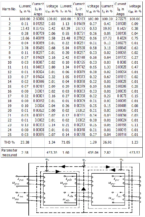
The no-load harmonic test was carried out on transformer having the rating of 100kVA, 11/0.433 kV, YNyn0. The results are as shown in table 1. The careful observation of results of %THD and magnitude of no-load current indicates that the magnitude of no-load current is within the range of limit but %THD in Y-phase is quite high compare to other two phases. In practical case the Y-phase no-load current is always have lesser magnitude and higher %THD compare to other two phases.
International Journal of Emerging Technology and Advanced Engineering
Website: www.ijetae.com (ISSN 2250-2459, Volume 2, Issue 2, February 2012)224
Whereas the magnitude of no-load current is less in Y-phase compare to other Y-phases because the reluctance offered to the flux of R and B-phase is quite high as the path for both the flux is from centre limb and two end limbs. But for Y-phase the reluctance offered to the flux is same for each end limbs and hence the magnitude of Y-phase no-load current is less (fig.3).In given transformer the Y-phase %THD in no-load current is quite high which needs to analyze for its magnetic behaviour. So by measuring only the no-load current of transformer we can predict the behaviour of transformer condition.
TABLEI
[image:3.612.44.289.297.665.2]HARMONIC ANALYSIS OF NO-LOAD CURRENT 100 KVA TRANSFORMER
Fig. 3 Transformer Flux Path
V. IDENTIFICATION OF WINDING FAULT
The winding fault can be present in HV, LV or in both. Now to identify that the inter turn fault in HV, LV or both the no-load harmonic test is useful indicator. If there is inter turn fault in primary then no-load harmonic test results in to increase in %THDi & magnitude of no-load current, whereas if the inter turn fault is in secondary then the no-load harmonic test results in to increase in magnitude of no-load current only. The practical result leads to the same conclusion.
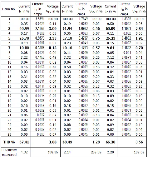
TABLE II
HARMONIC ANALYSIS OF NO-LOAD CURRENT FOR 10 KVA TRANSFORMER
[image:3.612.321.556.325.648.2]International Journal of Emerging Technology and Advanced Engineering
Website: www.ijetae.com (ISSN 2250-2459, Volume 2, Issue 2, February 2012)225
(B) FAULT IN PRIMARY (R-PHASE)TABLE III
HARMONIC ANALYSIS OF NO-LOAD CURRENT FOR 100 KVA TRANSFORMER, FAULT IN SECONDARY (R-PHASE)
[image:4.612.44.281.132.403.2]The results from table II (b) shows that the increase in %THDi and magnitude of no-load current for inter turn fault in primary. And the table III shows the no-load harmonic test results for inter turn fault in secondary winding of R-phase. For the simulation of inter turn fault the tapings available on the windings are shorted with external link as shown.
Fig. 4 Simulation of Inter-turn Fault
The results obtained are practical and from table III it is clear that for applied voltage of 104 the no-load current drawn is 20 A. This large amount of current reflects the winding fault in any of the winding. To identify that the inter turn fault in which winding, harmonic analysis of no-load current was done. And the results from table II (b) and table III clearly shows that if the inter turn fault present in primary then %THDi and magnitude of no-load current both will increase, where as if the inter turn fault is on secondary then only magnitude of no-load current will increase.
VI. CONCLUSION
[image:4.612.333.569.214.390.2]International Journal of Emerging Technology and Advanced Engineering
Website: www.ijetae.com (ISSN 2250-2459, Volume 2, Issue 2, February 2012)226
VII. REFERENCES
[1] Aiman Hassan Al-Haj and Ibrahim El-Amin, 2000, Factors That Influence Transformer No- Load Current Harmonic, IEEE Transaction on Power Delivery Vol.15 No.1.
[2] George J.Wakliesh, Power System Harmonics: Fundamentals, Analysis & Design, 1stedition, Springer publications, New York, USA.
[3] I.Daut, Syafruddin Hasan, Soib Taib, Risnidar Chan, M.Irwanto, June-2010, Harmonic Content as Indicator of Transformer Core Saturation, Selngor, Malaysia.
[4] IEEE: 519:1992, IEEE Recommended Practices and Requirements for Harmonic Control in Electrical Power Systems.
[5] Liao Ruijin, Sun Caixin, Chen Weigen, Wang Caisheng, Sept.1998, On-Line Detection of Gases Dissolved in transformer Oil and the Faults Diagnosis, Toyohashi, Japan.
[6] Robert D. Henderson, Patrick J. Rose, June 1994, Harmonics: The effect on Power Quality and
Transformers, North Carolina, USA.