64:5 (2013) 13–17 | www.jurnalteknologi.utm.my | eISSN 2180–3722 | ISSN 0127–9696
Full paper
Jurnal
Teknologi
Comparison Between Two Different Types of Microcontroller in
Developing Optical Tomography Controller Unit
M. Fadzli Abdul Shaiba*, Ruzairi Abdul Rahimb, Siti Zarina M. Mujia, Naizatul Shimab, Mohd Zikrillah Zawahirb
aFaculty of Electrical & Electronic Engineering, Universiti Tun Hussein Onn Malaysia, 86400, Parit Raja,Batu Pahat, Johor Darul Takzim, Malaysia bProcess Tomography and Instrumentation Engineering Research Group (PROTOM-i), Infocomm Research Alliance, Faculty of Electrical Engineering,
Universiti Teknologi Malaysia, 81310 UTM Johor Bharu, Johor, Malaysia
*Corresponding author: [email protected]
Article history
Received :1 May 2013 Received in revised form : 9 July 2013
Accepted :5 August 2013
Graphical abstract
Abstract
This paper describes the comparisons on the usage of different PIC microcontroller towards the development of optical tomography controller for fan beam projection. The advantage and disadvantage for each PIC towards the development of tomography sensors is discussed. The transmission and receiving conditioning circuit integrate with PIC is presented and explained. This paper is vital for further development of optical tomography system as a whole system.
Keywords: Optical tomography; microcontroller
© 2013 Penerbit UTM Press. All rights reserved.
1.0 INTRODUCTION
Process tomography is one of the online imaging techniques to observed internal characteristic of material flow inside the pipeline without the needs to obstruct the material flow. Early revolution of tomography started for medical purpose which is then been applied for industrial application where online monitoring is concerned [1]. Optical Tomography is one of the branches in tomography which is generally applied to observed mixture of solid and gas (e.g. granular flow or liquid and gas (e.g. water in bubble column) [2]. Indeed, there are several other tomography techniques available but optical tomography is considered safest technique since this sensors is equally sensitive to parameter measured in all position throughout the measurement volume and its sensitivity is independent on the distribution inside and outside measurement region [3].
In initial step on developing optical tomography, the determination of suitable microcontroller is crucial to ensure this system function in real time manner. The main function of using PIC microcontroller is to create activation pulse for transmitting signal from sensors device. Besides, this microcontroller also needed to convert analogue data from receiving sensors to digital data for further manipulation by PC.
Most of the previous researchers utilising the combination of the PIC microcontroller or designed circuit with Data Acquisition System (DAQ) [4-6,13] and the others using the combination of different PIC microcontroller using I2C protocol
to develop optical tomography system [7]. This is due to limiting of port available for most of the microcontroller for converting analogue data to digital form. The usage of DAQ can capable to convert the analogue the, the cost of each DAQ card is very high. The other alternative of method of data conversion could be considered.
2.0 SENSORS CONFIGURATION FOR OPTICAL TOMOGRAPHY
The main concept in optical tomography involves the attenuation of light when the particle flowing across the pipe obstructs the light beam projection [8]. This will cause lower reading of voltage across the receiver which is used to construct the tomogram.
Figure 1 Sensors configuration for OT system
Base on the sensors projection, appropriate transmitter and receiver conditioning circuit is needed to drive the IR LED sensors. For the operation of optical tomography system, there are several step need to be followed. Base on Figure 1, one of the transmitters is activate (e.g. Tx0) while the rest of the transmitter (Tx1 till Tx15) remains deactivate. At the same time, all the receiver (Rx0 till Rx15) receives the signal for further processed. The same process will be repeated for final transmitter Tx15. After all the reading signals from the transmitter are obtained, the signal will undergo the analogue to digital conversion before been processed for image reconstruction.
3.0 MANAGING PORT FOR SIGNAL TRANSMISSIONS AND RECEIVING DATA
On managing the activation of each transmitter (Tx0 till Tx16), the function of microcontroller is very important on executing the task. Indeed, there are variety types of microcontroller available such as PIC, dsPIC or ADUINO. In selecting which microcontroller could be used, there are several characteristics need to be considered. First is the amount of ports needed to activate each of the transmitters. In this case, 16 ports are needed to activate 16 transmitters. Next is the capability of selective port to convert the analogue data to digital (ADC) form. In case of fan beam optical tomography, 16 ADC port is needed since it consist of 16 receivers. Finally, the transmission for data switching and analogue data to be converted to digital form should be as quick as in microsecond. Thus, in this case, there are two microcontroller to be considered which are PIC 18F4520 and dsPIC30F6014A. The characteristics of each PIC to fulfill the requirement will be analysed.
3.1 Managing Port for PIC18F4520
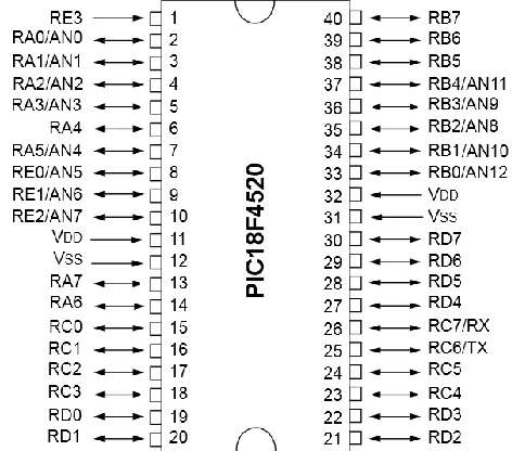
[image:2.612.322.558.60.268.2]As shown in Figure 2 and Table 1, PIC 18F4520 consists of 34 input/output ports. For development of optical tomography fan beam projection illustrated as Figure 1, 16 ports for this microcontroller is needed for transmitting signal while another 16 ports as receiver for antxalogue signal [10].
Figure 2 Input & Output arrangement for PIC18F4520
Table 1 List of input & output port for PIC18F4520
PORT
Total port number
RA0-RA5
6
RB0-RB7
8
RC0-RC7
8
RD0-RD7
8
RE0-RE3
4
[image:2.612.323.564.537.660.2]Before determine which port of this microcontroller giving signals to each of the transmitter, ADC ports need to be identified. In this case, 16 ports are needed to be use as ADC ports. As shown in Table 2, only 13 ports are available in this type of microcontroller. Hence, 13 ports will be used as ADC ports (master) and another 3 ports left will be obtained from another identical microcontroller (slave).
Table 2 List for ADC PORT
Analog to Digital Conversion(A DC) port
AN 0
AN 1
AN 2
AN 3
AN 4
AN 5
AN 6
AN 7
Port Number RA
0 RA 1
RA 2
RA 3
RA 5
RE 0
RE 1
RE 2
Analog to
Digital Conversion(A DC) port
AN 8
AN 9
AN 10
AN 11
AN 12
Port Number RB2 RB
3 RB 1
RB 4
RB 0
Table 3 List for transmitter ports
Transmitter Tx0 Tx1 Tx2 Tx3 Tx4 Tx5 Tx6 Tx7
Port Number RC0 RC
1 RC 2
RC 3
RC 4
RC 5
RD 0
RD 1
Port Number Tx8 Tx9 Tx
10 Tx 11
Tx 12
Tx 13
Tx 14
Tx 15
Port Number RD
2 RD 3
RD 4
RD 5
RD 6
RD 7
RB 6
RB 7
As shown from Table 3, most RC ports & RD ports will be used as port for transmitting signal except RC6 and RC7 since it already has been used for UART ports.
[image:3.612.326.564.333.516.2]As mention previously, for ADC process two microcontrollers is needed to execute the task. In order to communicate between two microcontrollers, the Universal Asynchronous Receiver/Transmitter (UART) ports will be used. The UART port is consist of port RC6 as Tx and RC7 as Rx. This port will be connected to another UART port at second microcontroller. As shown in Figure 3, port RC6 (Tx) from the first microcontroller will be connected to port RC7 (Rx) from the second microcontroller whereas port RC7 (Rx) from first microcontroller will be connected to Port RC6 (Tx) from second microcontroller. Both of the microcontrollers need to be ground at one common point.
Figure 3 UART connection
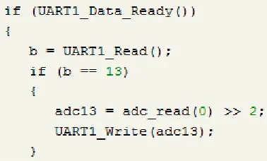
As shown from the source code below using Micro C compiler, the first microcontroller will trigger the second microcontroller by transmitting number 13 to the second microcontroller through UART port RC6.
When second microcontroller receive the numbers send by first microcontroller via UART port RC7, as shown in the source below, the analogue data will be converted into digital form then will be send back to first microcontroller via UART port RC6. The first microcontroller will received the digital data via UART port RC7 to the master microcontroller to be collected and send to PC.
For transferring the digital data from first microcontroller to PC, data will be transferred via UART. Since for PIC18F4520 only has one pairs of UART ports, virtual UART ports is introduced called “softUART”. In order to create “softUART”, any two unused port will be utilized as Rx and Tx port. Only 3 ports left for this microcontroller. Hence, port RB7 will be used as Rx and RA4 as Tx port. This port will be connected to serial communication port for transmission of digital data to PC side for further process. The source code almost the same as previous code expect need to write Soft_UART_Write for data transmitting to PC as shown below:
3.2 Managing Port for dsPIC30F6014A
As shown in Figure 4 and Table 4, dsPIC30F6014A microcontroller consists of 66 input/output ports [11]. As mention previously, optical tomography for fan beam configuration involved on activating 16 sensors for signal transmission purpose. For this microcontroller, all RB ports (RB0 until RB15) is use to activate transmitting signal which involved total 16 port.
Figure 4 Input/output port arrangements for dsPIC30F6014A
Table 4 List of input/output port for dsPIC30F6014A
Port
RA6-RA7
RA9-RA10
RA12-RA15
RB0-RB15
RC1-RC4
Total port number
2 2 3 16 4
Port
RC13-RC15
RD0-RD15
RF0-RF8
RG0-RG3
RG6-RG9
Total port number
3 16 4 4 4
Port
RG12-RG15
Total port number
[image:3.612.327.558.566.700.2] [image:3.612.58.247.601.715.2]For receiver side, as mention previously, total port needed for receiving analogue signal from the transmitter to be converted to digital signal is 16 ports. As shown from Table 5, dsPIC30F6014A consists of 16 analogue to digital conversion port (RB0 until RB15). This quantity is enough for the system to convert the entire analogue data received from the receiver of the optical sensors. In this case, all the data can be directly connected to all the port without the needs to communicate with other microcontroller to ensure adequate port is obtained. Source code below shows the conversion of analogue data to digital for one of the receivers Rx0.
Table 5 List for ADC port for dsPIC30F6014A
Analogue to Digital
Conversion(ADC) AN0 AN1 AN2 AN3
Ports RB0 RB1 RB2 RB3
Analogue to Digital
Conversion(ADC)
Port AN4 AN5 AN6 AN7
Ports RB4 RB5 RB6 RB7
Analogue to Digital
Conversion(ADC)
Port AN8 AN9 AN10 AN11
Ports RB8 RB9 RB10 RB11
Analogue to Digital
Conversion(ADC)
Port AN12 AN13 AN14 AN15
Ports RB12 RB13 RB14 RB15
After the analogue signal is converted to digital signal by ADC port, the data need to be transferred to PC. For dsPIC30F6014A, there are two UART point available which RF2 & RF3 are for UART1 and RF4 & RF5 for UART2. This means, all the digital data can be transferred to PC without the needs to introduce virtual UART as mention previously. In this case, RF2 & RF3 will be used for data transferring.
After the analogue data been converted to digital signal, the data can be transferred to PC using serial communication port. Since most of the current PC currently do not have serial port, Universal Serial Bus(USB) to UART converter module will be use to transfer the data[12]. Besides, ground need to be introduced as one common point between the microcontroller and USB to UART converter module. As shown source code below, there are two set of data need to be transferred, which are low byte and high byte data since for dsPIC30F6014A, it can give accuracy up to 12 bit data transferring.
4.0 INPUT & OUTPUT SIGNALS FROM Tx & Rx
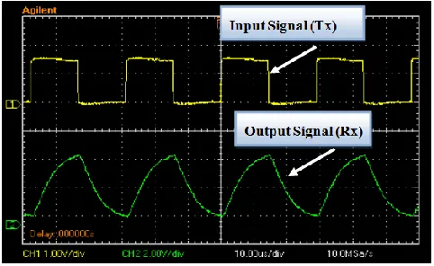
[image:4.612.54.289.257.452.2]As illustrated in Figure 5, the input signal is set to operate on frequency of 33kHz where the output signal obtained is 4.24V[9]. Rx signals shows voltage of the output increase gradually until steady state is achieve during activation state of Tx projection. During deactivation state, the voltage of the output will be reduced to zero gradually. The data from the Rx is in analogue form which will be converted to digital data by corresponding microcontroller. In this case either PIC18F4520 or dsPIC30F6014A can be used.
Figure 5 Signal from Tx and Rx of optical tomography system
5.0 CONCLUSIONS
Both of the microcontroller PIC 18F4520 and dsPIC30F6014A has its own advantage and disadvantage where it is depends on the applications. In this case, it clearly shown that for optical tomography which use 16 transmitters and 16 receivers, the usage of dsPIC30F6014A is better compared to PIC 18F4520. The reason is, with 16 ADC ports, dsPIC30F6014A will able to cater the entire analogue signal to be converted to digital signal from the transmitter. There is no need to communicate with other microcontroller to complement input port which is not enough for PIC18F4520. Besides, the programming for communication between two PIC is quite troublesome for PIC18F4520. Microcontroller dsPIC30F6014A has two UART points which is more than enough to transfer the digital data to PC for further processed. The transferring of digital data is not easy when using PIC18F4520 since virtual UART need to be introduced to replace UART point which has been used for analogue to digital conversion. This method also (virtual UART) is time consuming since it need time to convert normal port into UART port. However, if the input of the analogue data need to be processed is less or same with 8 data, PIC18F4520 is a good option since it could be cost effective and the initial set up for PIC18F4520 is much simpler compared to dsPIC30F6014A.
Acknowledgement
References
[1] Tomasz Dyakowski, Laurent F. C. Jeanmeure, Artur J. Jaworski. 2000.
Applications of Electrical Tomography for Gas–Solids and Liquid–
Solids Flows—A Review. Powder Technology. 112: 174–192.
[2] S. Ibrahim, et al. 2012. Concentration Measurements of Bubbles in a
Water Column Using an Optical Tomography System. ISA Transation.
51(6): 821–826.
[3] G A Johansen, T Frøystein, B T Hjertakery and Ø Olsen. 1996. A Dual
Sensor Flow Imaging Tomographic System. Meas. Sci. Technol. 7: 297–
307.
[4] Ruzairi Abdul Rahim, Jon Fea Pang, Kok San Chan. 2005. Optical Tomography Sensor Configuration Using Two Orthogonal and Two Rectilinear Projection Arrays. Flow Measurement and Instrumentation. 16(5): 327–340.
[5] Ruzairi Abdul Rahim, L. C. Leong, K. S. Chan, M. H. Rahiman, J. F.
Pang. 2008. Real Time Mass Flow Rate Measurement Using Multiple Fan Beam Optical. ISA Transactions. 47: 3–14.
[6] Yingna Zheng,Qiang Liu,Yang Li,Nabil Gindy. 2006. Investigation on
Concentration Distribution and Mass Flow Rate Measurement for
Gravity Chute Conveyor by Optical Tomography System. Measurement.
39: 643–654.
[7] S. Zarina Mohd Muji. 2012. Optical Tomography for Solid Gas
Measurement Using Mix Projection. Thesis, UTM.
[8] Green, R. G., Horbury, N. M., Abdul Rahim, R., Dickin, F. J., Naylor,
B. D. and Pridmore, T. P. 1995. Optical Fibre Sensors For Process Tomography. Meas. Sci. Technol. Meas. Sci. Technol. 6: 1699–1704.
[9] M. Fadzli B Abdul Shaib, Ruzairi Abdul Rahim, Siti Zarina M. Muji,
Leow. 2012. Pei Ling, M. Mahadi Abdul Jamil, A Study on Optical
Sensors Orientation for Tomography System Development. Sensors &
Transducers Journal. 140(5): 45–52. [10] Microchip. 2009. PIC18F4520 Data Sheet. [11] Microchip. 2011. dsPIC6014A Data Sheet.
[12] Siti Zarina M. Muji, Ruzairi Abdul Rahim. 2010. Two Microcontrollers Interaction Using C, Second International Conference on Computer Research & Development. 7-10 May. 290–292.
[13] R. Abdul Rahim. S.Z Mohd. Muji. January 2013. Optical Tomography: Image Improvement using Mix Projection of Parallel and Fan Beam
Mode. Measurement Journal (ISSN: 0263-2241). Elsevier Science. 46: