BRINGING ORDER IN SEGMENTS FOR A ROBUST NETWORK IN
MOBILE SERVICES
Abdulfattah Muhyiddeen, R. Mohd Nor and M. M. Hafizur Rahman Department of Computer Science, International Islamic University Malaysia, Kuala Lumpur, Malaysia
E-Mail: [email protected]
ABSTRACT
Common overlay network arranges nodes in a particular topology such as a ring, a tree or a hyper-tree on top of its’ physical network and takes advantage of its structure to improve network efficiency. The structured overlay network may provide efficient routing but the constructed structured network may not consider physical proximity in the physical network. The construction of any structured network requires nodes to be topologically sorted. Topologically sorting nodes is not a difficult task, however, to keep nodes in a correct state where transient faults exist like the overlay network created on top of the mobile network can be daunting. In this paper, we introduce an algorithm to improve the performance of an overlay network by ensuring physical proximity. Furthermore, the linearized nodes will self-stabilize to a correct state as soon as the transient fault stops. A segment based self-stabilizing linearizing algorithm that creates a linear overlay network (topologically sorting) over the mobile network is proposed.
Keywords: self stabilization, p2p, mobile networks, network efficiency.
INTRODUCTION
The advancement of technology in smart devices allows cheap and continuous access to the Internet. According to the Internet Live Stats [13], Internet users exceed 3 billion users and it is still growing in numbers. This statistics alone is a cautionary sign for public online systems such as social network and instant messaging services to redesign their network to be scalable to handle large number of users. One of the ways to deal with large number of users is to decentralize the load of the server where the burden of the server is distributed among users. However, this distributed approach comes with challenges. One of such challenges is the handling of transient faults.
In a large system, transient faults may occur quite frequently. Transient faults are faults that occur due to some temporary condition in the network such as a bit-flip due to lightning overcharge which may result in misconfiguration of the network or disconnection of network services due to temporary power failure. Even a small transient error in the slightest scale may snowball into crippling the whole system and affect all of the users if it is not managed properly. Such an incident can be a nightmare to maintain, time consuming and costly to repair, such as what is experience on 12th June 2015 where Level 3 (one of the world’s largest Internet Service Provider) had failed to handle the routing properly which resulted in disturbance of Internet service for several hours even after the routing fault was corrected [13]. In a traditional client-server model, clients use the help of a server to relay messages to utilize the use of storage, computation or network resources. A heavy load on the server due to overwhelming client activity can result in a bottleneck or worse crash the server. One solution to this is to distribute the server load.
In a distributed model, messages are relayed among several clients and servers, usually called nodes or
peers. Unfortunately, one of the challenges on distributing server load is to manage routing of messages that can be constantly changing with respect to link quality, network topology and network accessibility. Many applications of distributed systems manage its links to other nodes using distributed routing tables. Since routing information among nodes is distributed across the network, an occurrence of transient fault on any node could possibly affect the whole network. If the problem affects the rest of the network, repairing the network will be a very tedious task since it would be very hard to distinguish between a correct and wrong routing table that each node needs to use. Simply resetting the whole network will indeed be a cheaper and faster solution but this will destroy every ongoing transaction.
Our contribution in this paper is to propose a self-stabilizing algorithm to construct an efficient network for mobile devices. One of the key features of this algorithm is constructing an overlay network with linear topology by arranging nodes according to their GPS coordinate. In the linear topology, nodes are grouped within segments. These segments are fully utilized for routing purposes where nodes are not only identified by their identifier numbers, but also which segments they belong. The existence of a linear topology allows the construction of a structured overlay network commonly used to reduce the diameter of the network for efficient routing for example trees, hypertree, or skip-list [16] structure.
methodology section, we provide an informal description
of our solution. Later in our algorithm description section, we introduce the algorithm used in each node to construct a self-stabilizing linear network. The theoretical results section discuss the advantages of our algorithm. Finally, we explain our future research direction as well as the need for such solution in the future works and conclusion section.
RELATED WORK
In this paper, we present related work by researchers in the area of self-stabilizing algorithms, distributed computing and peer to peer field. According to Onus et al., [15], linearization is a basic and necessary step to arrange connected graphs. They proposed a linearization algorithm for random graphs in polylogarithmic time. Gupta et al. [1], later prove that performance of the network is determined by how the network is constructed and organized. The aim for all topology construction is to minimize the overlay routing hops. Therefore the linearization step in this case is necessary for making an efficient algorithm.
In a self-stabilizing network, nodes or peers in the network rely on message passing to send information to each other. However, a fundamental constraint exist as nodes crashes in the network. Mohd Nor et al., [18] highlighted that one of the fundamental constraints of peer to peer system is the impossibility to connect a disconnected network or discard peer identifiers that are not present in the system. Essentially, the author proves that peers can create two independent graphs, G1 and G2
and remain disconnected due to crashes. This problem exist because there is no way for a peer in graph G1 to
rediscover another peer in graph G2 if there is no path
from G1 to G2 .
The fundamental constraint can be circumvented if there exist an ever present node or super peer to provide the path from any disconnected graphs. Yang et al. [4], defined super peers as nodes that function as a server and also as similar as other peers at the same time. A super peer is expected to be reliable and does not suffer crashes. Super peers mainly exist to handle a fundamental constraint as nodes crashes in asynchronous distributed systems.
A few papers address self-stabilization of network topologies. The Iterative Successor Pointer Rewiring Protocol [9] and the Ring Network [20] organize the nodes in a sorted ring. Onus et al. [15] linearize a network into a sorted linked list. However, they use a simplified synchronized communication model for their algorithm. There are several studies of more sophisticated structures relying on networks to be initially topologically sorted. H´erault et al. [12] describe a self-stabilizing spanning tree algorithm. Caron et al. [6] present a Snap-Stabilizing Prefix Tree for peer-to-peer systems while Bianchi et al. [5] shows stabilizing peer-to-peer spatial filters. Clouser et al. [8] propose a deterministic
self-stabilizing skip list for shared register communication model while Mohd Nor et al. [17] propose a deterministic self-stabilizing 1-2 skip-list in a message-passing model with low atomicity suitable for peer-to-peer systems. Gall et al. [11] discuss models that capture the parallel time complexity of locally self-stabilizing networks that avoids bottlenecks and contention. Scheideler et al. [21] generalize insights gained from graph linearization to two dimensions and present a self-stabilizing construction for Delaunay graphs. In another paper, Jacob et al. [14] present a self-stabilizing, randomized variant of the skip graph and show that it can recover its network topology from any weakly connected state in O(log2 n) communication rounds with high probability in a simple, synchronized message passing model. Berns et al. [3] present a general framework for the self-stabilizing construction of any overlay network. However, the algorithm requires the knowledge of the 2-hop neighborhood for each node and involves the construction of a clique.
One of the closest to our approach is presented by Feldotto et al. [23] which considers bandwidth for construction of the topology rather than using physical proximity. The authors takes on a more practical parameter rather than relying on a logical parameter. However, Feldotto et al. paper differs to our approach as their main goal is to eliminate unnecessary hops and our parameter is to ensure physical proximity between peers remain local to their segments.
NOTATION AND COMPUTATIONAL MODEL In this section of this paper we will introduce some of the notations and computational model being used in this paper. An algorithm is considered reliable if it can tolerate and overcome any transient faults that occur during run time. Nodes in distributed systems should be self-stabilizing and able to reconstruct the network themselves, if for any reason the system is perturbed in any way.
An algorithm is considered scalable if it has good performance for joining a particular distributed network and good performance for routing messages from a specific source to a specific destination. Performance is measured by calculating number of hops for specific task: (i) construction, (ii) joining and leaving of nodes, (iii) routing messages.
The degree of autonomousity is measured by how minimal each node depends on outer resources such as a dedicated or a group of nodes to maintain the network and to route messages. The lesser amount of dependencies on other nodes, the higher the degree of autonomousity.
sending messages to it. Message routing is handled by the
underlying network. We thus assume that the nodes are connected by a communication channel. In a mobile service, we can assume such a channel is handled by the local mobile network operator such as EDGE, 3G or 4G networks.
For the computational model used in this paper, each node contains a set of variables and actions. A channel is a special variable type whose values are sets of messages. That is, we consider non-FIFO (First In First Out) channels. The channels may contain an arbitrary number of messages, i.e. the channels are unbounded. We assume that the only information any message can carry is node identifiers. We further assume that each message carries only one identifier. Message loss is not considered. Since message order is unimportant, we consider all messages sent to a particular node as belonging to the single incoming channel of this node.
METHODOLOGY
The algorithm works by sorting nodes in a linear topology which is divided into segments. Nodes are first grouped into segments based on their physical position and later, sorted according to their respective segments.
For the sake of discussion, let’s make the assumption that the network coverage is the whole peninsular of Malaysia. Albeit, this methodology can be applied to many different scenarios concerning network proximity based on several different metrics. For example, nodes can be divided into segments in an organization based on physical location proximity or in a hierarchy of bandwidth speeds based on network speeds proximity. It can also be in a specific regional locations across the globe based on hop count proximity. In the case of the whole peninsular of Malaysia, a number of super nodes are deployed across the region based on current telecommunication network providers. Each of the super node will represent a segment throughout the country. When other node joins the network, they will send a message to the closest super node and they will be linearized along this backbone according to the segment where the super node is located.
Since the assumption of this algorithm is for mobile services, it is fair to say that each node are given a unique identifier (a cell phone number, an IP address or a manufacturer assigned serial number) each. It can also be assumed that each node have the ability to know their own GPS coordinate via onboard GPS chip that exist on most mobile devices to indicate their physical position or rely on values provided by close by routers and cell-phone towers. Each node are interconnected in an existing network provided by the network provider of each mobile device. Following these assumptions, the construction of the topology is divided into several steps:
a. Super nodes
Super nodes are selectively distributed across the whole region. The algorithm behaves exactly the same with other nodes in a homogeneous manner, except the fact that a super node will never leave the segment. Super nodes will be a reference point for a newcomer node joining the system for the first time or a previous node who have left the network and require to rejoin the network. The super nodes are initially linearized to form a logical line which will construct an overlay network backbone.
b. Logical backbone and segmentation
A logical jagged line is drawn across the peninsular of Malaysia which will be the logical backbone of this algorithm. As initially describe, this is initially consist of super nodes. As shown in Figure-1, the logical backbone for the algorithm is targeted to create a linear topology among all interconnected nodes in the peninsular of Malaysia. The logical backbone is predefined in the algorithm and visible for all nodes by storing it in their memory. The backbone is divided into segments where all of the nodes will be grouped according to the closest segment it belongs to according to where they are physically located.
Figure-1. Logical backbone. The line is drawn across the peninsular of Malaysia. It is divided into segments. Each
segment is represented by a super node.
c. Location segment projection
the closest super node that represents the segment. For a
node to project on the closest segment, each node will calculate projection points on every segments available and compare the distance between the its’ position with the closest points on every segment to get which segment contain the closest projection point from their position. Then, nodes will be grouped into segments which contain the closest projection point to them. As discussed earlier in this section, each node has a unique identifier given to them by their network providers. Each node will then concatenate their segment number as a prefix to their identifier number. The concatenation of their segment number with their identifier number will be a new mutable identifier in this overlay network and will be used for the purpose of routing messages later.
d. Linearization
After the nodes are grouped into segments according to their physical locations, the nodes will start to linearize themselves. Nodes within the same segment will be sorted according to the identifier number while segments are sorted according to the segment numbers. Each segments will be connected to each other. To realize this, a special node (super node) is required for each segment which will be the reference points for all other nodes to enter the segments and for segments to be connected. These special nodes have similar property like other nodes, except there are ensured to be always alive in the network. Figure-2 illustrates the end results of 4 nodes after the linearization process. Each node is ordered by segment number first, then by its identifier.
Figure-2. Example of 4 nodes being linearized and written in “a-b” format. “a” indicates the segment number while “b” indicates the original id of the nodes. The figure shows
nodes are sorted according to the segment number first then the nodes original number.
e. Routing messages
Messages are routed from sender to receiver in several steps. The sender will extract the identifier number of the receiver to get its segment number. If the receiver is in the same segment with the sender, the sender will forward the message to other nodes within the same segment. Other nodes who receive the message will check whether the message belongs to them or not. If not, the messages will be forwarded until the message reaches the desired receiver. If the receiver is not within the same segment, the message will end being forwarded to a super node within the segment. The message will then be forwarded to the receiver’s segment directly utilizing the structured overlay network constructed on via the super
nodes. A node in the segment will receive the message and forwards it to the desired receiver.
ALGORITHM DESCRIPTION
The algorithm works by deploying several super nodes in several strategic locations. Later, each area where the super node exists is considered as a segment. The segments are numbered in sequence starting from the number 1. The location (GPS coordinate) of every super nodes are visible for all new coming nodes only. Each node will try to calculate which super node is the nearest to it. Once the node finds which super node is the nearest, the node will identify itself to be in the same segment by storing the segment number.
One of the advantages of peer-to-peer in distributed computing is it does not suffer from the problem of single point of failure. A super node is a node that acts like a centralized server for a specific task, which to some extend is unavoidable or rather needed to assure connectivity when all other nodes fail. The concept of having a super node might be contradicting with the aim of distributed computing as of this case. However, to circumvent the problem of crashed and non-existing identifiers in the network, implementation of a super node is unavoidable since it facilitate other nodes. Implementation of a super node is also a realistic approach since most network services rely on several servers with reliable up times. Specifically, the implementation of a super node in this paper is required due to the following constraints: (i) to be a reference point for newcomer nodes in specific segments (ii) to ensure all segments are connected.
Nodes may not be fairly distributed between segments in this algorithm, because it depends on their physical location. This is because the main aim of the algorithm is not to distribute the nodes fairly, but to avoid unnecessary hops across segments. Messages are routed directly to the desired segments before it reach desired node. Therefore, if messages is to be sent from a node to other node in its same segment, the message will not be sent further out of the segment first before reaching the receiver.
Assume originally all nodes has a unique serial number each, the node will identify itself by concatenating the segment number with its serial number. This concatenation of segment number and serial number is referred to as ID number for this algorithm and the ID number will be used throughout the algorithm for constructing, linearizing, stabilizing and routing process. The segment number is concatenated as a prefix to the serial number; therefore, nodes are first sorted according to the segment number. After that, they are sorted according to its serial number.
neighbor. For every cycle, each node will execute the
following steps:
1. read message and execute command from the message
2. send notification message every time out, send message to left node with parameter "1" and also right node (if exist) with parameter "2" indicating their neighbors that it is their direct neighbor.
When a node joins the network, it will set nearest super node as left neighbor and let the right neighbor empty (it can be positive infinity). In its first execution, it will notify its left neighbor (nearest super node initially) by sending a message with parameter "1" to tell the super node that they are currently neighbors. And then finish the execution.
When the super node or any node receive the message (notification) with parameter "1" it will check whether the node (sender of the message) is suitable to be its right neighbor (the sender's left if receiver's right) or not. There are several possibilities when receiving message with parameter "1":
i. If the sender's id is smaller than the receiver's id, and the sender's id is also smaller than receiver's left neighbor’s id, receiver will suggest the sender to set receiver's left neighbor as sender's left neighbor also (message with parameter "" (empty) and "sender's id").
ii. If the senders id is smaller than the receiver id, but the sender id is bigger than receiver's left neighbor’s id, the receiver will send a message to its left neighbor to suggest it to make the sender as its right neighbor (message with parameter "4" and "sender's id"). Then receiver will set its left neighbor as sender and notify the sender about that (message with parameter "1")
iii. If sender's id is bigger than receiver's id, but smaller than receiver's right neighbor’s id, the receiver will send a message to its right neighbor to suggest it to make the sender as its left neighbor (message with parameter "3" and "sender's id"). Then receiver will set its right neighbor as sender and notify the sender about that (message with parameter "2")
iv. If the sender's id is bigger than the receiver's id, and the sender's id is also bigger than receiver's right neighbor’s id, receiver will suggest the sender to set receiver's right neighbor as sender's left neighbor. v. If the sender's id is smaller than the receiver's id but
receiver’s left neighbor is negative infinity (receiver is the left most node), receiver will make sender as its left neighbor and notify the sender about that.
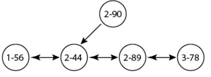
Figure 3-a illustrates a node with segment number 2 and identifier 90 trying to join the segment number 2. The mutable id for this node is 2-90. The node with mutable id 2-90 tries to calculate the segment it
belongs to by comparing its id with a list of other ids belonging to other super nodes in its algorithm. Following the algorithm mentioned in this section, node with id 2-90 will eventually receive a message from node id 2-44 about node id 2-89. The node will then try to contact node 2-89 and attached itself as node 2-89 right neighbor. The result of this process is known as linearization as it linearizes nodes according to their ids. An illustration of this is shown in Figure-3b.
Figure-3a. Linearization process. Node 1-56, 2-46, 2-89 and 3-78 are already linearized. Node 2-90 wants to join the network. Bidirectional arrow indicates both node store each other’s id and aware that they are neighbors. Unidirectional arrow indicates that only one node make the other node as neighbor, not the other way round. In this example, node 2-90 sends a message to 2-44 when making it as neighbor. Receiving the message, node 2-44 will send 2-89’s id to 2-90. Upon receiving the id, 2-90 will also send message to 2-89 to join the network.
Figure-3b. When node 2-89 realized that 2-90 is bigger than it but smaller than its right neighbor, 2-89 make 2-90 as its new right neighbor and ask 3-78 to make 2-90 as its new left neighbor. Finally, all nodes are successfully linearized.
THEORETICAL RESULTS
Each peer updates its links based on messages it receive in its incoming channel. It does not depend on any global knowledge or information from other peers other than messages it receive from other peers. Therefore, each peer behaves independently. It must be noted here that if a transient fault occurs, the incoming message in a peer may be incorrect. This will cause the network to be in an incorrect state. However, once the transient fault stops, the network will correct itself since the algorithm will process messages that are sent by other peers and process those messages locally. It will not depend on the results of other nodes in the network.
[image:5.612.325.536.214.291.2]
relatively far away in the logical overlay network. This
could happen when nodes that are right next to each other have significantly huge distance in their logical space id. For example, a node with id 10 is relatively very far away from a node with id 400. Since nodes are arranged using their identifiers in an overlay network, 2 peers can be significantly far away in the overlay network. To illustrate the effects of this, let us refer to Figure-4 for example. If node ‘A’ wants to send a message to node ‘E’, physically it can be done directly without sending the message through other nodes in the physical network but in the logical network or overlay network, it cannot be done directly. Node with identifier ‘A’ needs to send the data to the node with identifier ‘B’ first, and when node with identifier ‘B’ received the message it will forward this message to node identifier ‘C’ and so on until it reach node with identifier ‘E’. This is obviously result in an inefficient method to routing messages.
In another case, if a node with identifier ‘A’ wants to send a message to another with node identifier ‘B’ and at the same time a node with identifier ‘E’ wants to send a message to another node with identifier ‘F’, on the logical network it might seems that this two messages does not cross each other’s path. However, an overlay network exist on top of the physical network and relies on the physical network to relay messages. This will result on a bottleneck occurring on a gateway or on a shared path along the routes in the physical network. In this scenario, it shows that a good algorithm on a logical network might not give the same performance on the existing physical network because it does not take proximity in consideration. Therefore, considering the GPS coordinate of the nodes for construction of the logical network topology helps to increase the performance of routing in the distributed network.
Figure-4. Mapping between an existing networks with an overlay network in a linear topology.
FUTURE WORKS
This paper discuss the use of physical proximity in linearizing nodes for the purpose of constructing a linearize set of peers on the overlay network. It is known through literature that a complex network can only be constructed if nodes are initially topologically sorted. The existence of an overlay network with linearize identifiers allows the construction of a more complex structured network that can be implemented to reduce the diameter of the overall network. Since linear networks performs poorly, O(n) complexity, the future direction of this research area is to develop an algorithm that can construct a structured network similar to hyper trees, trees or skip-list to reduce the network complexity to O(log N).
To extend this research further, a simulation study could be done to compare theoretical results with simulation results. It is expected that this algorithm will locally try to fix its left and right neighbor during a transient fault and eventually construct a correct state for a system with linearize nodes. However, it would interesting to see to what extent the network can reconstruct itself despite recurring transient faults.
On the implementation of super node in this algorithm, ideally super nodes should be more decentralized and peers should be less dependent on super nodes. This opens up to a huge number of research area pertaining to maintaining peers to be part of a cluster of super nodes rather than a single super node.
Finally, the algorithm can be further improved by introducing more parameters for the linearization process such as bandwidth, type of node (phone or computer), type of sub network and so forth which will make the algorithm more practical to be implemented (in smart phone era).
CONCLUSIONS
This study will contribute to enhance distributed computing systems which are currently an ongoing trend, especially after the introduction of the cloud computing and big data concept in mobile devices network. Distributed computing is very good in managing huge storages. Matei et al., [19], Chao et al., [7] and Chu et al., [10] also mentioned that distributed computing has become an important method for huge data processing across platforms. According to Sinha et al., [22] distributed computing also can be used to solve complex calculation by distributing the task of calculation to multiple computers to generate the results.
ACKNOWLEDGEMENTS
This paper is made possible through funding provided by Ministry of Education under the RAGS program (RAGS 12-042-0042).
REFERENCES
[1] Ankur Gupta, Lalit K. Awasthi. 2011. Peer-to-Peer Networks and Computation: Current Trends and Future, Computing and Informatics, Vol 30, No 3, 2011.
[2] A. Rowstron, P. Druschel. 2001. Pastry, Scalable, distributed object location and routing for large-scale peer-to-peer systems. In Proc. of Middleware.
[3] Berns, A., Ghosh, S., Pemmaraju, S.V. 2010.: Brief announcement: a framework for building self-stabilizing overlay networks. In: Proc. of the 29th
ACM Symp. on Principles of Distributed Computing (PODC), pp. 398–399.
[4] Beverly Yang, Hector. 2003. Designing a Super-peer Network.
[5] Bianchi, S., Datta, A., Felber, P., Gradinariu, M. 2007. Stabilizing peer-to-peer spatial filters. In: ICDCS 2007: Proceedings of the 27th International
Conference on Distributed Computing Systems, p. 27. IEEE Computer Society Press, Washington, DC, USA.
[6] Caron, E., Desprez, F., Petit, F., Tedeschi, C. 2010. Snap-stabilizing prefix tree for peer-to-peer systems. Parallel Processing Letters 20(1), 15–30.
[7] Chao Jin, Christian Vecchiola, Rajkumar Buyya. 2008. MRPGA: An Extension of MapReduce for Parallelizing Genetic Algorithms, Fourth IEEE International Conference on eScience, pp.214-221
[8] Clouser, T., Nesterenko, M., Scheideler, C. 2008. Tiara: A Self-stabilizing Deterministic Skip List. In: Kulkarni, S.S., Schiper, A. (eds.) SSS 2008. LNCS, vol. 5340, pp. 124–140. Springer, Heidelberg.
[9] Cramer, C., Fuhrmann, T. 2005. Self-stabilizing ring networks on connected graphs. Technical Report 2005-5, System Architecture Group, University of Karlsruhe.
[10] C.T. Chu, S. K. Kim, Y.-A. Lin, Y. Yu, G. Bradski, A. Y. Ng, and K. Olukotun. 2007. Map-reduce for machine learning on multicore, Advances in Neural Information Processing Systems .Cambridge, MA: MIT Press, pp. 281-288.
[11] Gall, D., Jacob, R., Richa, A., Scheideler, C., Schmid, S., Täubig, H. 2010.: Time complexity of distributed topological self-stabilization: The case of graph linearization, pp. 294-305
[12] Hérault, T., Lemarinier, P., Peres, O., Pilard, L., Beauquier, J. 2006. Brief Announcement: Self-stabilizing Spanning Tree Algorithm for Large Scale Systems. In: Datta, A.K., Gradinariu, M. (eds.) SSS 2006. LNCS, vol. 4280, pp. 574-575. Springer, Heidelberg.
[13] Internet Live Stats. 2015. Retrieved on July 13, 2015, from http://www.internetlivestats.com.
[14] Jacob, R., Richa, A., Scheideler, C., Schmid, S., Täubig, H. 2009. A distributed polylogarithmic time algorithm for self-stabilizing skip graphs. In: Proc. of the 28th ACM Symp. on Principles of Distributed
Computing (PODC), pp. 131-40.
[15] Onus, M., Richa, A., Scheideler, C. 2007. Linearization: Locally self-stabilizing sorting in graphs. In: Proc. 9th Workshop on Algorithm
Engineering and Experiments (ALENEX). SIAM, Philadelphia.
[16] Pugh, W. 1990. Skip lists: A probabilistic alternative to balanced trees, Communications of the ACM 33.
[17] Rizal Mohd Nor, Mikhail Nesterenko, Christian Scheideler. 2011. Corona: A Stabilizing Deterministic Message-Passing Skip List, Stabilization, Safety, and Security of Distributed Systems, Lecture Notes in Computer Science Volume 6976, 2011, pp 356-370.
[18] Rizal Mohd Nor, Mikhail Nesterenko, Sébastien Tixeuil. 2011. Linearizing Peer-to-Peer Systems with Oracles, Stabilization, Safety, and Security of Distributed Systems Lecture Notes in Computer Science Volume 8255, 2013, pp 221-236.
[19] Matei Zaharia, Andy Konwinski, Anthony D. Joseph, Randy H. Katz and Ion Stoica. 2008. Improving MapReduce Performance in Heterogeneous Environments, OSDI 2008, pp. 29-42.
[20] Shaker, A., Reeves, D.S. 2005. Self-stabilizing structured ring topology P2P systems. In: Proc. 5th
IEEE International Conference on Peer-to-Peer Computing, pp. 39–46.
[22] Sinha, A., Saini, T., Srikanth, S.V. 2014. Distributed
computing approach to optimize road traffic simulation, Parallel, Distributed and Grid Computing (PDGC), 2014 International Conference pp.360,364.