Cloud-‐Based Structural Model Conversion and Analysis
Thesis By
Christopher G. Janover, P.E.
In Partial Fulfillment of the Requirements
For the Degree of
Doctor of Philosophy
California Institute of Technology Pasadena, California
2016
© 2015
Christopher G. Janover, P.E.
Acknowledgements
I would like to begin by thanking The California Institute of Technology for
providing me with an outstanding education and financial support over the last four
years, as well as the opportunity to do research in a field about which I have grown so
passionate.
I would like to thank my two advisors, Dr. Tom Heaton and Dr. John Hall, who
have guided me through my experience at Caltech. They gave me the freedom to pursue
research in a field in which I was immensely interested, and were always there to offer
guidance when it was needed.
I wish to thank the MCE staff for their hard work which allowed me to focus on
my education and research.
I would also like to express my gratitude to my fellow graduate students who
spent the past four years with me. The time we spent together studying for our
qualification exams, doing homework, and doing research made the whole process
more enjoyable. A special thank you to Arnar Bjornsson, Grant Hollis, Ryan Hurley, and
Ramses Mourhatch for their help testing and vetting my work. A huge thank you to
Anthony Massari, who spent the past three years working closely with me. Anthony
spent a great deal of his time helping me fix my problems and come up with great ideas.
I would like to extend a large thank you to my amazing girlfriend Adriana
Carmona, who spent nearly the past three years putting up with me throughout this
you were the not-‐so-‐calm force who did all of the worrying for me. You were the best
and this would have been much more difficult without you. A thank you to Sherlock for
being the best corgi around.
Above all I would like to thank my parents. Everything I have accomplished is
because of your guidance and unwavering support. You are always looking out for me
and always have my best interest in mind. Without you, none of this would have been
Abstract
STEEL, the Caltech created nonlinear large displacement analysis software, is
currently used by a large number of researchers at Caltech. However, due to its
complexity, lack of visualization tools (such as pre-‐ and post-‐processing capabilities)
rapid creation and analysis of models using this software was difficult. SteelConverter
was created as a means to facilitate model creation through the use of the industry
standard finite element solver ETABS. This software allows users to create models in
ETABS and intelligently convert model information such as geometry, loading, releases,
fixity, etc., into a format that STEEL understands. Models that would take several days to
create and verify now take several hours or less. The productivity of the researcher as
well as the level of confidence in the model being analyzed is greatly increased.
It has always been a major goal of Caltech to spread the knowledge created here
to other universities. However, due to the complexity of STEEL it was difficult for
researchers or engineers from other universities to conduct analyses. While
SteelConverter did help researchers at Caltech improve their research, sending
SteelConverter and its documentation to other universities was less than ideal. Issues of
version control, individual computer requirements, and the difficulty of releasing
updates made a more centralized solution preferred. This is where the idea for Caltech
VirtualShaker was born. Through the creation of a centralized website where users
could log in, submit, analyze, and process models in the cloud, all of the major concerns
allows users to create profiles where defaults associated with their most commonly run
models are saved, and allows them to submit multiple jobs to an online virtual server to
be analyzed and post-‐processed. The creation of this website not only allowed for more
rapid distribution of this tool, but also created a means for engineers and researchers
with no access to powerful computer clusters to run computationally intensive analyses
without the excessive cost of building and maintaining a computer cluster.
In order to increase confidence in the use of STEEL as an analysis system, as well
as verify the conversion tools, a series of comparisons were done between STEEL and
ETABS. Six models of increasing complexity, ranging from a cantilever column to a
twenty-‐story moment frame, were analyzed to determine the ability of STEEL to
accurately calculate basic model properties such as elastic stiffness and damping
through a free vibration analysis as well as more complex structural properties such as
overall structural capacity through a pushover analysis. These analyses showed a very
strong agreement between the two softwares on every aspect of each analysis.
However, these analyses also showed the ability of the STEEL analysis algorithm to
converge at significantly larger drifts than ETABS when using the more computationally
expensive and structurally realistic fiber hinges. Following the ETABS analysis, it was
decided to repeat the comparisons in a software more capable of conducting highly
nonlinear analysis, called Perform. These analyses again showed a very strong
agreement between the two softwares in every aspect of each analysis through
instability. However, due to some limitations in Perform, free vibration analyses for the
story moment frame could not be conducted. With the current trend towards ultimate
capacity analysis, the ability to use fiber based models allows engineers to gain a better
understanding of a building’s behavior under these extreme load scenarios.
Following this, a final study was done on Hall’s U20 structure [1] where the
structure was analyzed in all three softwares and their results compared. The pushover
curves from each software were compared and the differences caused by variations in
software implementation explained. From this, conclusions can be drawn on the
effectiveness of each analysis tool when attempting to analyze structures through the
point of geometric instability. The analyses show that while ETABS was capable of
accurately determining the elastic stiffness of the model, following the onset of inelastic
behavior the analysis tool failed to converge. However, for the small number of time
steps the ETABS analysis was converging, its results exactly matched those of STEEL,
leading to the conclusion that ETABS is not an appropriate analysis package for analyzing
a structure through the point of collapse when using fiber elements throughout the
model. The analyses also showed that while Perform was capable of calculating the
response of the structure accurately, restrictions in the material model resulted in a
pushover curve that did not match that of STEEL exactly, particularly post collapse.
However, such problems could be alleviated by choosing a more simplistic material
Contents
Acknowledgements ... iii
Abstract ... v
Contents ... viii
List of Figures ... xii
List of Tables ... xvi
Introduction ... 17
Software Discussion ... 20
1 SteelConverter ... 22
1.1 STEELCONVERTER -‐ INTRODUCTION ... 22
1.2 ETABS MODEL CREATION ... 24
1.2.1 Grid System ... 25
1.2.2 Line Elements ... 26
1.2.3 Restraints ... 29
1.2.4 Releases ... 30
1.2.5 Loading / Load Combinations ... 30
1.2.6 Sections / Custom Sections ... 31
1.2.7 Springs ... 31
1.2.8 Walls ... 31
1.2.9 Decking ... 32
1.2.10 Materials ... 34
1.3 STEELCONVERTER CONFIGURATION FILE ... 35
1.4 POST PROCESSING TOOLS ... 46
1.4.1 LoadData ... 46
1.4.2 Plot Undeformed Shape ... 47
1.4.3 Plot Dynamic Analysis ... 51
1.5 COMMENTARY ... 54
1.5.1 Diaphragms ... 54
1.5.2 Vertical Connection Elements ... 56
1.5.3 Modeling of Secondary Frames ... 58
1.5.4 Rayleigh Damping ... 58
1.5.5 Releases ... 59
1.5.6 Damping / Special Columns ... 64
1.5.7 Special Columns ... 64
1.5.8 Recommended Values ... 67
1.5.9 Element Strong Axis / Weak Axis Orientation ... 70
1.5.10 Nodal Mass ... 71
1.5.11 Decking ... 71
1.5.13 Gravity ... 72
1.5.14 Panel Zones ... 72
1.5.15 Element Connectivity ... 73
1.5.16 Axial Load Eccentricity ... 74
1.5.17 Node Numbering ... 74
1.6 STEEL INPUT FILES ... 76
1.6.1 for001 ... 76
1.6.2 for002 ... 84
1.6.3 for003 ... 84
1.6.4 for020 ... 84
1.6.5 for021 ... 84
1.6.6 for029 ... 85
1.7 RUNNING STEEL ON A PBS SERVER ... 86
1.7.1 Directory Setup ... 86
1.7.2 Server Scripts ... 86
1.7.3 Submitting a Job ... 90
1.7.4 Monitoring Results ... 90
1.8 SAMPLE 6 STORY MODEL ... 92
1.8.1 ETABS Model ... 92
1.8.2 Sample .e2k file ... 94
1.8.3 Sample SteelConverter Configuration File ... 94
1.8.4 Sample STEEL Input File ... 94
1.8.5 Sample STEEL Output File ... 94
1.9 CHANGE LOG ... 95
2 Caltech VirtualShaker ... 96
2.1 INTRODUCTION ... 96
2.2 GETTING STARTED ... 97
2.2.1 Running the U6 – Base sample model ... 97
2.2.2 Creating a Model with the Baseline Default ... 106
2.3 VIRTUALSHAKER BACK-‐END DESCRIPTION ... 108
2.3.1 Amazon Web Services ... 108
2.3.2 EC2 Servers ... 109
2.3.3 S3 Cloud Storage ... 111
2.3.4 SQS Messaging ... 112
2.3.5 SQL Database Design ... 113
2.4 FEATURES ... 116
2.4.1 Creating an Account ... 116
2.4.2 Creating Defaults ... 118
2.4.3 Modifying a Default ... 120
2.4.4 Uploading Ground Motions ... 121
2.4.5 Creating a Model ... 123
2.4.6 Creating an Analysis ... 125
2.4.7 Customizing an Analysis’s Configuration ... 127
2.4.8 Submitting an Analysis ... 128
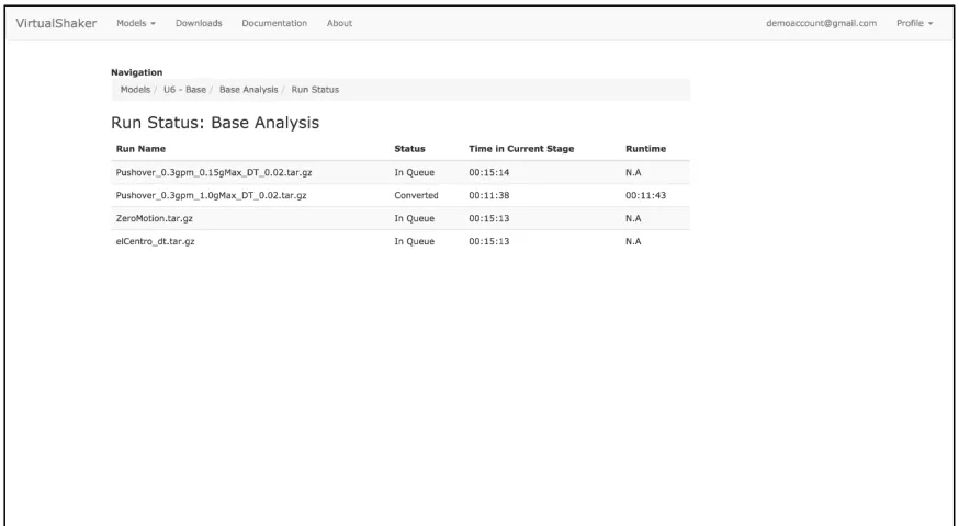
2.4.9 Viewing Analysis Status ... 129
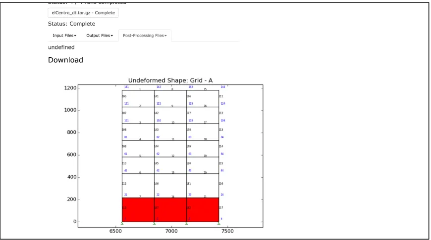
2.4.10 Viewing / Downloading Results ... 131
2.4.12 Documentation ... 134
2.5 RESULTS & POST-‐PROCESSING ... 136
2.5.1 Input Files ... 136
2.5.2 Output Files ... 136
2.5.3 Post-‐Processing Files ... 137
2.6 CONFIGURATION DESCRIPTION ... 140
2.6.1 Model Information ... 140
2.6.2 Analysis Options ... 141
2.6.3 Damping Options ... 143
2.6.4 Diaphragm Options ... 145
2.6.5 Convergence Options ... 146
2.6.6 Fiber Options ... 147
2.6.7 Vertical Constraint Options ... 148
2.6.8 Load & Post-‐Processing Options ... 150
2.6.9 Response Time History Options ... 152
2.6.10 Material Model Options ... 154
2.6.11 Foundation Node Options ... 155
2.7 CHANGELOG ... 157
3 STEEL Verification ... 158
3.1 ETABS TO STEEL COMPARISON ... 158
3.1.1 Introduction ... 158
3.1.2 ETABS Model Description ... 159
3.1.3 Material Model Description ... 160
3.1.4 Analysis Discussion ... 161
3.1.5 Cantilever Column ... 162
3.1.6 Three Story Moment Frame ... 166
3.1.7 Three Story One Bay Chevron Brace Frame ... 170
3.1.8 Two Bay Three Story Moment Frame ... 175
3.1.9 Two Bay Chevron Brace Frame ... 181
3.1.10 Twenty Story Moment Frame ... 188
3.2 PERFORM3D STEEL COMPARISON ... 193
3.2.1 Introduction ... 193
3.2.2 Perform3D Model Description ... 194
3.2.3 Material Model Description ... 195
3.2.4 Perform3D Analysis Limitations ... 197
3.2.5 Analysis Discussion ... 199
3.2.6 Cantilever Column ... 200
3.2.7 Three Story Moment Frame ... 204
3.2.8 Three Story One Bay Chevron Brace Frame ... 207
3.2.9 Two Bay Three Story Moment Frame ... 210
3.2.10 Two Bay Chevron Brace Frame ... 213
3.2.11 Twenty Story Moment Frame ... 216
3.3 TWENTY STORY ANALYSES ... 219
3.3.1 Introduction ... 219
3.3.2 Software Description ... 220
3.3.3 Model Description ... 221
3.3.5 Software Limitations ... 231
3.3.6 Pushover Analysis Comparison ... 233
3.3.7 Nepal Time History Analysis ... 239
3.4 CONCLUSION ... 251
3.5 LESSONS LEARNED ... 254
Works Cited ... 256
Appendix ... 259
APPENDIX A – SAMPLE 6-‐STORY X-‐BRACE BUILDING .E2K FILE ... 259
APPENDIX B – SAMPLE STEELCONVERTER CONFIGURATION FILE ... 282
APPENDIX C -‐ SAMPLE STEEL FOR001 INPUT FILE ... 286
APPENDIX D – SAMPLE STEEL SECTION CONVERSION FILE ... 302
APPENDIX E – SAMPLE STEEL SLAB CONVERSION FILE ... 310
APPENDIX F – SAMPLE STEEL SEED FILE (FOR029) ... 311
APPENDIX G – SAMPLE STEEL GRID CONVERSION FILE ... 312
APPENDIX H – SAMPLE STEEL MATERIAL CONVERSION FILE ... 313
APPENDIX I – SAMPLE STEEL SECTION CONVERSION FILE ... 314
List of Figures
Figure 1-‐1 -‐ Example ETABS Grid Systems ... 25
Figure 1-‐2: Example of Non-‐Acceptable and Acceptable Element Meshing ... 26
Figure 1-‐3: Example of Acceptable and Non-‐Acceptable Column Placement ... 28
Figure 1-‐4: ETABS Column Bracing Requirement ... 29
Figure 1-‐5: ETABS Decking Input ... 32
Figure 1-‐6: STEEL Decking Input ... 33
Figure 1-‐7: Acceptable ETABS Deck Placement ... 33
Figure 1-‐8: STEEL Diaphragm Depiction ... 54
Figure 1-‐9: Vertical Connection Elements -‐ Core ... 56
Figure 1-‐10: Vertical Connection Elements -‐ Outrigger ... 57
Figure 1-‐11: Extra Restraints placed on Secondary Frames ... 58
Figure 1-‐12: STEEL Element Fiber Description ... 60
Figure 1-‐13: STEEL Beam/Column Segment Description ... 60
Figure 1-‐14 -‐ Special Column Force Distribution ... 66
Figure 1-‐15: STEEL Beam, Column, and Brace Element Connectivity Information ... 73
Figure 1-‐16: STEEL Basement Wall Element Connectivity Information ... 73
Figure 1-‐17: Axial Load Eccentricity Factor Variable Description ... 74
Figure 1-‐18: Automatic Node Numbering Technique for SteelConverter ... 75
Figure 1-‐19: STEEL Slab and Deck Input Dimensions ... 84
Figure 1-‐20: 6 Story Example Structure – Isometric View ... 93
Figure 2-‐1 -‐ Downloads ... 97
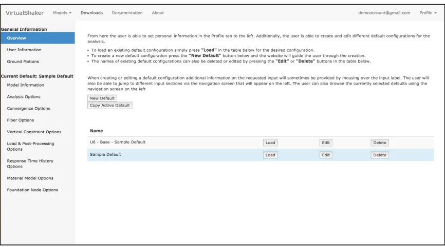
Figure 2-‐2 -‐ Profile Overview ... 98
Figure 2-‐3 -‐ Profile Overview with U6 -‐ Base default active ... 99
Figure 2-‐4 -‐ New Model ... 99
Figure 2-‐5 -‐ Model Created ... 100
Figure 2-‐6 -‐ New Analysis ... 101
Figure 2-‐7 -‐ Analysis Created for sample model ... 102
Figure 2-‐8 -‐ Sample Analysis Submitted ... 103
Figure 2-‐9 -‐ Sample Model Run Status Tooltip ... 103
Figure 2-‐10 -‐ Sample Model Run Status page ... 104
Figure 2-‐11 -‐ Sample Model Results Page ... 104
Figure 2-‐12 -‐ Sample Model Undeformed Shape ... 105
Figure 2-‐13 -‐ Baseline Default Profile Overview ... 107
Figure 2-‐14 -‐ AWS Workflow ... 108
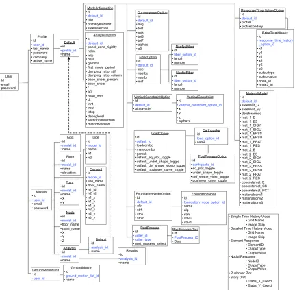
Figure 2-‐15 -‐ VirtualShaker SQL Database ... 115
Figure 2-‐16 -‐ Home Page: Login ... 116
Figure 2-‐17 -‐ New User: Login Screen ... 117
Figure 2-‐19 -‐ Default Overview ... 119
Figure 2-‐20 -‐ Typical Default Options Page ... 120
Figure 2-‐21 -‐ Configuration Tooltip ... 121
Figure 2-‐22 -‐ Ground Motions Upload ... 122
Figure 2-‐23 -‐ Model Creation ... 124
Figure 2-‐24 -‐ Model Analysis Listing ... 124
Figure 2-‐25 -‐ Models Listing ... 125
Figure 2-‐26 -‐ New Analysis ... 126
Figure 2-‐27 -‐ Analysis Options ... 126
Figure 2-‐28 -‐ Configuration Overview ... 128
Figure 2-‐29 -‐ Configuration Example ... 128
Figure 2-‐30 -‐ Model Submitted ... 129
Figure 2-‐31 -‐ Run Status Popup ... 130
Figure 2-‐32 -‐ Detailed Run Status ... 130
Figure 2-‐33 -‐ Results Page ... 131
Figure 2-‐34 -‐ Results Dropdown ... 132
Figure 2-‐35 -‐ Results Embedded Image ... 133
Figure 2-‐36 -‐ Downloads Page ... 134
Figure 2-‐37 -‐ Documentation Page ... 135
Figure 2-‐38 -‐ New Post-‐Process ... 137
Figure 2-‐39 -‐ Model Information ... 141
Figure 2-‐40 -‐ Analysis Options ... 142
Figure 2-‐41 -‐ Damping Options ... 144
Figure 2-‐42 -‐ Diaphragm Options ... 145
Figure 2-‐43 -‐ Convergence Options ... 146
Figure 2-‐44 -‐ Fiber Options ... 148
Figure 2-‐45 -‐ Vertical Constraint Options ... 149
Figure 2-‐46 -‐ Load & Post Processing Options ... 151
Figure 2-‐47 -‐ Load & Post-‐Processing Options -‐ Analysis Configuration ... 152
Figure 2-‐48 -‐ Response Time History Options ... 153
Figure 2-‐49 -‐ Material Model Options ... 154
Figure 2-‐50 -‐ Foundation Node Options ... 156
Figure 3-‐1 -‐ STEEL Material Model Description [1] ... 161
Figure 3-‐2 -‐ Cantilever Column Model Description ... 163
Figure 3-‐3 -‐ Cantilever Column -‐ Free Vibration Analysis ... 164
Figure 3-‐4 -‐ Cantilever Column – Pushover Analysis ... 165
Figure 3-‐5 – Three Story Moment Frame -‐ Model Description ... 167
Figure 3-‐6 -‐ Three Story Moment Frame -‐ Free Vibration Analysis ... 168
Figure 3-‐7 -‐ Three Story Moment Frame -‐ Pushover Analysis ... 169
Figure 3-‐8 -‐ Three Story One Bay Chevron Brace Frame -‐ Model Description ... 171
Figure 3-‐9 -‐ Three Story One Bay Chevron Brace Frame -‐ Free Vibration Analysis ... 172
Figure 3-‐10 -‐ Three Story One Bay Chevron Brace Frame -‐ Pushover Analysis ... 173
Figure 3-‐11 -‐ Three Story Chevron Brace Frame – Pushover Analysis -‐ Scaled ... 174
Figure 3-‐13 -‐ Two Bay Three Story Moment Frame -‐ Force Assignments ... 176
Figure 3-‐14 -‐ Two Bay Three Story Moment Frame -‐ Free Vibration Analysis ... 178
Figure 3-‐15 -‐ Two Bay Three Story Moment Frame -‐ Free Vibration Analysis -‐ Shifted . 178 Figure 3-‐16 -‐ Two Bay Three Story Moment Frame -‐ Pushover Analysis ... 179
Figure 3-‐17 -‐ Two Bay Three Story Moment Frame -‐ Pushover Analysis -‐ Scaled ... 180
Figure 3-‐18 -‐ Two Bay Three Story Chevron Brace Frame -‐ Sections ... 182
Figure 3-‐19 -‐ Two Bay Three Story Chevron Brace Frame -‐ Forces ... 182
Figure 3-‐20 -‐ Two Bay Three Story Chevron Brace Frame -‐ Free Vibration Analysis ... 184
Figure 3-‐21 -‐ Two Bay Three Story Chevron Brace Frame -‐ Free Vibration Analysis -‐ Shifted ... 184
Figure 3-‐22-‐ Two Bay Three Story Chevron Brace Frame -‐ Pushover Analysis ... 186
Figure 3-‐23 -‐ Two Bay Three Story Chevron Brace Frame -‐ Pushover Analysis -‐ Scaled 187 Figure 3-‐24 -‐ Twenty Story Moment Frame -‐ Section Assignments ... 189
Figure 3-‐25 -‐ Twenty Story Moment Frame -‐ Column and Girder Schedule ... 189
Figure 3-‐26 -‐ Twenty Story Moment Frame -‐ Free Vibration Analysis ... 191
Figure 3-‐27 -‐ Twenty Story Moment Frame -‐ Pushover Analysis ... 192
Figure 3-‐28 -‐ Material Model Description -‐ Perform3D vs. STEEL ... 196
Figure 3-‐29 -‐ Cantilever Column -‐ Free Vibration Analysis -‐ Perform ... 201
Figure 3-‐30 -‐ Cantilever Column -‐ Pushover Analysis -‐ Perform ... 202
Figure 3-‐31 -‐ Three Story Moment Frame -‐ Free Vibration Analysis -‐ Perform ... 205
Figure 3-‐32 -‐ Three Story Moment Frame -‐ Pushover Analysis -‐ Perform ... 206
Figure 3-‐33 -‐ Three Story One Bay Chevron Brace Frame -‐ Free Vibration Analysis -‐ Perform ... 207
Figure 3-‐34 -‐ Three Story Chevron Brace Frame -‐ Pushover -‐ Perform ... 208
Figure 3-‐35 -‐ Two Bay Three Story Moment Frame -‐ Free Vibration Analysis -‐ Perform211 Figure 3-‐36 -‐ Two Bay Three Story Moment Frame -‐ Pushover Analysis -‐ Perform ... 212
Figure 3-‐37 -‐ Two Bay Chevron Brace Frame -‐ Free Vibration Analysis -‐ Perform ... 214
Figure 3-‐38 -‐ Two Bay Chevron Brace Frame -‐ Pushover Analysis -‐ Perform ... 215
Figure 3-‐39 -‐ Twenty Story Moment Frame -‐ Free Vibration Analysis -‐ Perform ... 216
Figure 3-‐40 -‐ Twenty Story Moment Frame -‐ Pushover Analysis -‐ Perform ... 217
Figure 3-‐41 -‐ U20 -‐ Model Description ... 224
Figure 3-‐42 -‐ U20 -‐ Structural Details ... 225
Figure 3-‐43 -‐ J20 -‐ Model Description ... 226
Figure 3-‐44 -‐ J20 – Structural Details ... 227
Figure 3-‐45 -‐ Fiber Element Description ... 228
Figure 3-‐46 -‐ U20 Material Model Comparison ... 231
Figure 3-‐47 -‐ U20 -‐ Pushover Comparison ... 234
Figure 3-‐48 -‐ U20 Pushover Comparison -‐ STEEL vs ETABS ... 235
Figure 3-‐49 -‐ U20 STEEL & Perform Collapse Mechanism Comparison ... 237
Figure 3-‐50 -‐ Nepal Epicenter Locations [21] ... 240
Figure 3-‐51 -‐ Nepal Intensity Plot [21] ... 240
Figure 3-‐52 -‐ Nepal Ground Motion Sensor Readings [21] ... 241
Figure 3-‐53 -‐ U20 Pushover results for perfect and brittle connections ... 244
Figure 3-‐55 – Snapshot Time History Response of U20 Structure to Nepal Ground Motion ... 247
Figure 3-‐56 -‐ U20P -‐ Residual Interstory Drift of Structure Subjected to Nepal Ground Motion ... 248
Figure 3-‐57 -‐ Snapshot of Time History Response of J20 Structure to Nepal Ground Motion (J20P and J20B Results are identical) ... 249
Figure 3-‐58 -‐ J20 -‐ Residual Interstory Drift of Structure Subjected to Nepal Ground Motion (J20P and J20B results are identical) ... 249
List of Tables
Table 1-‐1: STEEL Element Release Definitions ... 64
Table 2-‐1 -‐ Post-‐Processing Options ... 138
Table 2-‐2 -‐ Model Information Options Description ... 141
Table 2-‐3 -‐ Analysis Options Descriptions ... 143
Table 2-‐4 -‐ Damping Option Descriptions ... 144
Table 2-‐5-‐ Diaphragm Option Descriptions ... 145
Table 2-‐6-‐ Convergence Options Descriptions ... 147
Table 2-‐7 -‐ Fiber Options Descriptions ... 148
Table 2-‐8 -‐ Vertical Constraint Options Descriptions ... 150
Table 2-‐9 -‐ Load & Post Processing Options Descriptions ... 151
Table 2-‐10 -‐ Response Time History Options Descriptions ... 153
Table 2-‐11 -‐ Material Model Options Descriptions ... 155
Table 2-‐12 -‐ Foundation Node Options Descriptions ... 156
Table 3-‐1 -‐ PFA Calculation Values ... 245
Table 3-‐2 -‐ PFA and Time History Result Comparison ... 250
Introduction
In the process of analyzing a structure there are a number of different finite element
packages available to an engineer. Very often, particular programs excel in a specific facet of
analysis such as concrete structures, post-‐tensioned slabs, nonlinear analyses etc. At the
California Institute of Technology a nonlinear large displacement finite element software,
STEEL, was created by Professor John Hall with the goal of providing detailed fiber based
analysis of steel structures. Through time, STEEL has developed into an analysis tool used by
many researchers at Caltech due to its ability to accurately model highly nonlinear behavior in
structures. However, with this increase in ability came an increase in complexity. The process of
learning to use STEEL is a difficult one due to the system’s lack of pre-‐ and post-‐processing
abilities, and its text-‐based input methodology.
SteelConverter was created as a means of simplifying the creation of these nonlinear
models through the use of the popular, industry standard, finite element package ETABS.
SteelConverter allows engineers and researchers to create models in ETABS and intelligently
import them into STEEL. A model creation process that previously took days or weeks to
complete can now be accomplished in minutes or hours. SteelConverter not only allows users
to import geometric model properties, but also includes information such as loading, load
combinations, scale factors, releases, and more. These properties are converted from ETABS
creating STEEL input files through various model-‐specific spreadsheets was eliminated, and this
new software allows Caltech researchers to use a unified program to create their models.
SteelConverter not only decreases the production time of models but also dramatically
decreases the likelihood of errors. For example, allowing researchers to apply loads directly to
nodes and combine them with scale factors greatly reduces the chance that values would be
inputted incorrectly because the ability to visualize the information was made available.
It has always been a major goal of Caltech to spread the knowledge created here to other
universities. However, due to the complexity of STEEL it was difficult for researchers or
engineers from other universities to conduct analyses. While SteelConverter did help
researchers at Caltech improve their research, sending SteelConverter and its documentation to
other universities was less than ideal. Issues of version control, individual computer
requirements, and the complexity associated with releasing updates made a more centralized
solution preferred. This is where the idea for Caltech VirtualShaker was born. Through the
creation of a centralized website where users could log in, submit, analyze, and process models
in the cloud, all of the major concerns associated with the effective utilization of SteelConverter
were eliminated. Caltech VirtualShaker allows users to create profiles in which the defaults of
their most commonly run models are saved, and allows them to submit multiple jobs to an
online virtual server to be analyzed and post-‐processed. The creation of this website not only
allows for more rapid distribution of this tool, but also creates a means for engineers and
researchers with no access to powerful computer clusters to run computationally intensive
The creation of SteelConverter and Caltech VirtualShaker helps extend the ability for
researchers to use the tools created by Caltech and helps aid in the distribution of knowledge
throughout the field of engineering.
Software Discussion
As the demand to analyze structures in increasingly complicated and sophisticated
manners grows, the capabilities of the softwares used for these analyses must as well. Finite
element analysis software is used throughout the industry for nearly every aspect of the
analysis / design process and countless analysis packages have been developed to meet the
individual needs of each engineering task.
The majority of structural analysis falls under the category of linear elastic. This type of
analysis is done at most structural engineering firms and is used to analyze structures for
loading environments such as gravity, wind, and seismic. For these types of analysis it is
beneficial for the software to contain features such as automated design to assist the engineer
with the most up-‐to-‐date analysis code. The softwares which are by far the most commonly
used for this type of analysis is SAP2000 and ETABS developed by Computers and Structures
Inc. (CSI) [2]. This software allows engineers to easily construct models, apply loads, and run
linear elastic analyses. It also has functionality for more advanced, nonlinear inelastic analyses;
however, it is not used primarily for this. There are many other softwares which accomplish the
same goals as SAP2000 and ETABS, such as OpenSees [3] and ANSYS [4] but their market share
in the private sector is significantly less.
For more complex finite element analyses there is a different set of software researchers
will use that are still being developed by companies. Softwares such as Perform3D [5] [6] by CSI
or LS DYNA [7], created by the Livermore Software Technology Corporation (LSTC). Perform 3D
large array of elements with both linear and nonlinear properties as well as numerous pre-‐built
structural engineering elements make it an ideal choice for the analysis of standard building
structures to more advanced loading environments. LS DYNA is capable of full 3D nonlinear
rigid body dynamics as well as being able to analyze more advanced properties like crack
propagation, failure analysis, and fracture.
It is not uncommon for research institutions and analysis firms to develop their own FEA
software to meet their individual needs. Software like, STEEL [1], created by Dr. John Hall at the
California Institute of Technology, was created to more accurately analyze steel structures at
large strains. With features like probabilistic brittle weld failure, a complex material model, and
nonlinear damping researchers at Caltech have been able to more accurately predict the
ultimate capacity of structures and their behavior during collapse [8] [9] [10]. Dr. Krishnan
created the 3D analysis tool FRAME3D based off of STEEL that implements many of the same
features including elements such as a plastic hinge element and elastofiber beam element and
utilizes a Newton-‐Raphson iteration strategy applied to an implicit Newmark time-‐integration
scheme [11] [12]. Drain-‐2D and Drain-‐2DX, created by Dr. Powell at the University of California,
Berkeley [13] [14] is widely used in the research community to study collapse behavior of
structures. Post September 11th, 2001 the National Information Service for Earthquake
Engineering has done extensive analyses on the necessary steps engineers must take when
designing high-‐profile structures to prevent progressive collapse due to an extraordinary
1
SteelConverter
1.1
SteelConverter -‐ Introduction
SteelConverter is an automatic model generation tool for the in-‐house non-‐linear analysis
software STEEL created by Professor John Hall at The California Institute of Technology.
SteelConverter allows the user to create models in the widely used analysis and design tool
ETABS from Computers and Structures Inc. and import many of the modeled parameters into a
text file STEEL understands.
This software was written to aid in the research of graduate students at Caltech as well as
allow researchers from other universities to begin utilizing STEEL without the steep learning
curve that comes with learning a new piece of software. Additionally, since STEEL has no
graphical user interface, creating large models with no errors can be difficult and time
consuming. SteelConverter aims to alleviate this by allowing the user to utilize the graphical
front end of ETABS.
SteelConverter is custom software written in C++ by Christopher Janover at The California
Institute of Technology and works by parsing through the text-‐based save file created by ETABS
(.e2k file) along with supplemental information in the form of a configuration file, reorganizing
the data, and then outputting to a format STEEL understands. Additionally, several post-‐
processing tools have been created in Matlab that allow the user to more easily visualize the
This manual will begin by demonstrating to the user how to properly make models in
ETABS by going through every type of element and property available for importing and
discussing acceptable modeling techniques. Next, a detailed discussion of the SteelConverter
configuration file is done to give the user a thorough understanding of how SteelConverter uses
this file to supplement data imported from ETABS. Following this, some of the post-‐processing
tools created in Matlab to assist in visualization of the results are discussed and their source
code is given. A commentary section is also included in this manual that discusses the inner
workings of both SteelConverter and STEEL and goes through the assumptions made in the
current version of the conversion software in addition to methods and techniques to modify
the input files to meet the individual needs of the user.
Additionally, this manual gives a detailed description of the format of the STEEL input
files so the user may manually modify input to meet their personal needs. Following this, a
description of the steps necessary as well as the source code needed to run multiple analyses
simultaneously on a PBS server is given, allowing the user to rapidly analyze a model for a series
of ground motions. Lastly, an example problem is given for a six story braced frame building
developed by Anthony Massari at Caltech. The ETABS .e2k file, SteelConverter configuration
file, and STEEL input files are all given to allow the user to verify proper modeling technique.
Additionally, ground motions and the results from the analysis can also be made available upon
request.
To obtain the most current version of STEEL, SteelConverter, and this manual email
[email protected], and the files and executable will be provided. For any questions,
1.2
ETABS Model Creation
There are several rules and assumptions made by SteelConverter that must be followed
when creating an ETABS model. All STEEL models must have an orthogonal Primary and a
Secondary direction where the Primary direction is the direction in which earthquake motions
will be applied. Since STEEL is a 2D analyses software, to model 3D structures as accurately as
possible several specialty elements have been developed which, in conjunction with
SteelConverter, transform the full 3D ETABS model into a series of 2D projections in a roughly
equivalent STEEL model.
However, since it is impossible to fully capture certain 3D affects in 2D analysis, such as
torsion and bi-‐axial bending, certain restrictions must be made on the ETABS model to yield an
accurate 2D representation. First, it is recommended that all ETABS models to be imported be
symmetric in the direction the system is being loaded, as this will reduce the amount of torsion
in the structure. Second, the lateral system should be designed to avoid the occurrence of
biaxial bending. This means avoiding moment connections in two orthogonal directions on a
single column. For more information on the 3D to 2D conversion see sections 1.5.2 and 1.5.3
For all STEEL models the direction that is considered Primary will contain the majority of
the column elements and is the major focus of the analysis. The choice of Primary vs. Secondary
Direction will be specified in the SteelConverter configuration file (which will be discussed later
in the manual) allowing for general model construction in both orthogonal directions in ETABS
without regard to this constraint. However, the user will be made aware of how their
placement of elements affects which grouping the elements are placed into. More information
1.2.1
Grid System
Grids in ETABS can be created utilizing either the default “Quick Templates” or the grid
editor inside the model. All grids must be orthogonal and there are hardly any restrictions on
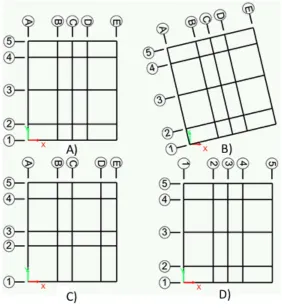
spacing or labeling. Images of example grid system can be seen in Figure 1-‐1.
Figure 1-‐1 -‐ Example ETABS Grid Systems
The grid system shown in part A) of Figure 1-‐1 is an acceptable grid system because it is
symmetric, and has unique grid labels and gridlines which are tangent to either the X or Y
directions. The grid system in part B) is not acceptable because the grid system has been
rotated away from the X and Y-‐axis. The grid system in part C) is acceptable; however, it is not
[image:25.612.147.429.200.508.2]be captured properly in the 3D to 2D conversion. Finally, the grid system in part D) is not
acceptable because of the non-‐unique grid labels.
1.2.2
Line Elements
The three types of line elements in ETABS that can be converted to STEEL are columns,
beams, and braces. All three have similar restrictions with some additional restrictions placed
on columns.
1.2.2.1 General Line Element Restrictions
All line elements must be divided at the intersection of any connecting element or break
in floor, while in software such as ETABS it is possible for an “auto-‐meshing” feature to be
enabled. In STEEL if the line elements are not meshed they will behave as though they are not
connected. This situation often arises when constructing the lateral system in the model. An
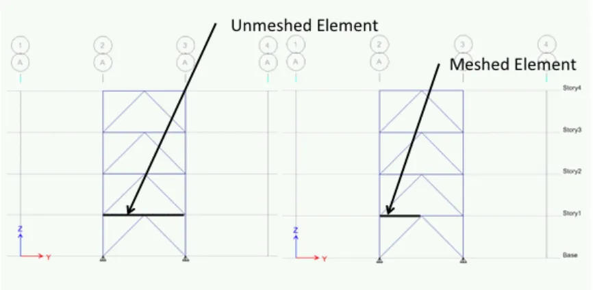
example of an acceptable and not acceptable element meshing can be seen in Figure 1-‐2.
Figure 1-‐2: Example of Non-‐Acceptable and Acceptable Element Meshing
[image:26.612.81.514.447.659.2]The image on the left shows that the beam spanning over the Chevron brace is not
meshed at the intersection of the brace at the midpoint of the beam. This results in the STEEL
model treating this configuration as a simply supported beam and a freestanding set of braces.
This can be resolved in the model by selecting all elements and using the “divide all frames at
intersection” feature located under the Edit-‐>Divide Frame menu. The result of this is the image
on the right of Figure 1-‐3. Here the beam spanning between the columns has been divided in
two and now meshes at the intersection point of the chevron brace.
1.2.2.2 Column Element Restrictions
The placement of column elements in ETABS affects how SteelConverter treats these
elements. Columns in ETABS must either be placed at the intersection of two grid locations or
on a gridline running parallel to either the X or Y-‐axis. It is not acceptable to place a column in
free-‐space. Examples of acceptable column placements can be seen in Figure 1-‐3. Placing a
column at the intersection of two gridlines results in SteelConverter treating that column as
Primary. If a column is placed solely on a gridline that runs parallel to the Primary Direction
then the column is treated as Primary. Similarly, if the column is placed solely on a gridline that
runs parallel to the Secondary Direction, then the column is treated as Secondary.
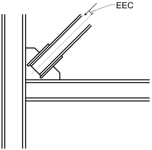
While all columns in ETABS default to strong axis bending in the X direction it is possible
to import column orientation from ETABS to STEEL. This can be accomplished by selecting a
column and assigning a local axis rotation of 90 degrees. This will cause the element to have
Figure 1-‐3: Example of Acceptable and Non-‐Acceptable Column Placement
1.2.2.3 Beam Element Restrictions
All beam elements placed in ETABS must run parallel to either the Primary or Secondary
Directions. It is not acceptable to have a beam that runs diagonally. A beam element will be
treated as Primary if it runs parallel to the Primary direction and will be treated as Secondary if
it runs parallel to the Secondary direction. Additionally, all columns must be braced on every
floor by a beam. It is not acceptable to have a column spanning more than one floor without a
beam framing into it, as it will cause instability in the model. It is therefore required that the
user place pinned infill beams between all columns even if no lateral system exists at that
Figure 1-‐4: ETABS Column Bracing Requirement
1.2.2.4 Brace Element Restrictions
All brace elements must run in a plane parallel to the Z-‐axis. A brace is considered to be
Primary if it lies in a plane parallel to the Primary Direction and is considered to be Secondary if
it lies in a plane parallel to the Secondary Direction. Additionally, HSS sections may only be used
as brace elements.
1.2.3
Restraints
Any node in the STEEL model can be restrained by assigning restraints in the ETABS
model. Nodes can be restrained in horizontal and vertical directions (UX, UY, UZ) as well as
rotation about the X and Y-‐axis (RX, RY). If the Primary Direction of the model is the X direction
and the model is restrained in the UX, UZ, RY and the node is Primary, then it will be treated as
fixed, while if the node is Secondary then it will be a horizontal roller.
Any combination of restraints can be used in the model, however. It is traditional to only
1.2.4
Releases
Any element in the STEEL model can be given releases by assigning releases in the ETABS
model. SteelConverter is capable of importing only moment releases into STEEL. A more
detailed discussion on releases can be found in Section 1.5.5.
1.2.5
Loading / Load Combinations
Only point loads can be transferred to STEEL and all loads must be placed in a load
combination. STEEL imports two load combinations that are specified in the SteelConverter
configuration file by name. Therefore, it is possible to have more combinations created in
ETABS and run multiple sets of STEEL analyses by changing the important load combination in
the SteelConverter configuration file. Steel uses these two load combinations to apply static
loading and mass on the model; therefore it is advised to create load patterns in ETABS for
loads such as dead, live, roof, etc. and then combine them with the appropriate load factors
into a named combination to be applied to the STEEL nodes. When creating the mass
combination assign the loads as a weight in the appropriate unit (i.e., N, lb.) and SteelConverter
will apply the mass in both the vertical and horizontal directions on the Primary frames.
It is not acceptable to create combinations of combinations in ETABS. Similarly, all
combination and pattern names must be unique. Additionally, only nodal loading is imported
into STEEL.
1.2.6
Sections / Custom Sections
SteelConverter is able to assign the appropriate sections to STEEL given section assigns
from ETABS. Both premade and custom sections can be utilized however, only wide-‐flange and
tube shapes are currently implemented. Additionally, any tube section used in the model must
have a section name that begins with HSS. To create a custom section use either the I/Wide
Flange or the Box/Tube Section tool in the Define-‐>Section Properties-‐>Sections-‐>Add New
Property menu and give the section a unique name. It is not acceptable to leave sections with
the default section type (FSEC-‐1). SteelConverter will automatically convert US section
properties to Metric when the ETABS .e2k file is exported in a metric unit.
1.2.7
Springs
SteelConverter has the ability to import the location of springs from ETABS into STEEL;
however, specific properties about the spring are assigned via the SteelConverter configuration
file. To assign a node in STEEL with a specific spring property, define a linear spring type in
ETABS with the same name as the non-‐linear spring definition in the SteelConverter
configuration file. For more information how to implement springs see spring input description
in Section 1.3.
1.2.8
Walls
Wall elements in ETABS can be used to create basement wall elements in STEEL.
SteelConverter only imports the name and location of the wall elements from ETABS. Specific
All ETABS wall elements must be rectangular and be drawn vertically. These elements are
usually drawn on the bottom floor. Custom sections can be created via the built-‐in ETABS wall
element section definition form. For more information on the function of basement wall
elements see Section 1.3.
1.2.9
Decking
SteelConverter has the ability to import both the ETABS deck definitions and locations
into STEEL. When defining a deck property in ETABS take note of the different definitions
meanings between ETABS and STEEL to ensure the element is defined properly. Figures
showing the ETABS deck definition window with visual representation can be seen in Figure 1-‐5,
while a figure showing deck input in STEEL format can be seen in Figure 1-‐6. Note that
SteelConverter automatically converts from ETABS format to STEEL format.
Figure 1-‐5: ETABS Decking Input
Figure 1-‐6: STEEL Decking Input
In the current version of SteelConverter only one type of deck may be present on a
particular floor. It is not acceptable to draw a floor with multiple deck properties or with
decking only a particular location. An example of an acceptable method of placing deck
elements in ETABS can be seen in Figure 1-‐7. For more information on these limitations see
Section 1.5.11.
Figure 1-‐7: Acceptable ETABS Deck Placement
1.2.10
Materials
As the material models used in STEEL are more complex than those used by ETABS,
material element assignments or definitions are not directly imported from ETABS. Rather, the
user assigns a material to each ETABS element, defines the STEEL material in the SteelConverter
configuration file with a lookup between ETABS material name and STEEL material number. This
is discussed in more detail in the SteelConverter configuration explanation in Section 1.3.
1.3
SteelConverter Configuration File
In order for SteelConverter to convert the ETABS .e2k file into the STEEL input file several
options in a configuration file must be set. Comments can be made in the Configuration file by
utilizing a ‘%’ before any text the user wants the parser to ignore. Each configuration option is
preceded by a tag inside of brackets (i.e. [ExTH]). The order of the tags does not matter,
however, it is recommended that the user does not alter the order. Each input to the
configuration file will now be gone through and explained.
• Program Output Information
o [DEBUG] – Toggle to enable or disable debug output (yes or no) § Currently not implemented
o [SECTIONCONVERSION] – Toggle to enable or disable output of section conversion table (yes or no)
o [MATERIALCONVERSION] – Toggle to enable or disable output of material conversion table (yes or no)
• Model Information
o [TITLE] – Title of the model (Name output data will saved as)
o [SAVELOC] – Location where input and output files will be saved do (don’t include trailing / in directory)
o [ETABSTITLE] – Title of ETABS file (Name of .e2k file to be read from)