© 2018, IRJET | Impact Factor value: 6.171 | ISO 9001:2008 Certified Journal | Page 1770
Simulation for Standalone PV System on MPPT Control with Battery
Pallavi Mohapat Bhure
1, Prof. Pratik Ghutke
2, Dr. Hari Kumar Naidu
31
M-Tech scholar, Electrical Department, TGPCET Mohgaon, Nagpur, Maharashtra, India
2Assistant Professor, Electrical Department, TGPCET Mohgaon, Nagpur, Maharashtra, India
3HoD Electrical Engineering, Electrical Department, TGPCET Mohgaon, Nagpur, Maharashtra, India
---***---
Abstract - In the modern world, to decreasing the usages
of fossil fuel consumption for that generate electricity from renewable resources is to use solar cells to convert solar irradiance into electricity. Currently Photovoltaic (PV) energy generation has a great commercial and great academic interest. To increase the efficient irrigation in agriculture to power DC pumps. It is provide the power at all time even at cloudy days. Maximum Power Point Tracking (MPPT) controls of standalone PV system with battery to supply power to the loads. This system implies battery is an energy storage element and it can be used as a power source when PV is insufficient for the same. The system comprises of a battery, PV panel and a boost converter circuit. The paper consists of both software and hardware design. The boost converter tracks the Maximum Power Point (MPP) of the PV panel by controlling the duty cycle and then it is given as a gate pulse to the Boost Converter. The function of battery is to maintain a constant dc-link voltage. Incremental Conductance method is used as Maximum Power Point Tracking (MPPT) control algorithm. MATLAB SIMULINK is used to create a simulation model of the Standalone-PV system and then the output is verified.
Key Words
:
Maximum Power Point Tracking (MPPT),Photovoltaic system, solar energy, Battery, Inverter, Boost Converter.
1. INTRODUCTION
Standalone-PV systems are generally used for isolated loads or household purposes. The increase in power demand in the utility side with less harmonics and fluctuation are the major issues .The conventional sources of energy have the probability to last for limited time but renewable sources of energy like solar energy is infinite and also eco-friendly. With the increased efficiency of power electronics devices we can use this solar energy to provide the power to the consumers. The only flaw of solar energy is that the set-up required is quite expensive. The output power of PV depends on many criteria’s like isolation and temperature. With variation in these two parameters the output is also varied, which will thereby lead to fluctuation in the utility side, which is totally undesirable. So it is important to have a control which will make our solar panel’s output totally independent of weather conditions. Currently there are many algorithms like incremental inductance, perturbation and observation, fuzzy logic etc. In this paper we totally concentrate on the method of Incremental Conductance Method. This algorithm controls the duty cycle of boost converter and it is given as gate pulse to the converter
then. The battery used here is like an energy storage element. It not only maintains dc link voltage across the capacitor constant but also supplies to the load during bad weather conditions when PV is unable to generate the power required by the load. A standalone PV system has many practical applications. The simulation results and the hardware design shows that Standalone-PV system can be efficiently used for isolated loads. The solar cell operates at very low efficiency to increase the efficiency of the solar cell better control mechanism are required. To avoid the faults and damage the appliances for that developed what now are called the Maximum Power Point Tracking (MPPT) algorithms. The variation of sun’s inclination to track the maximum possible power from the incoming solar radiations, the control mechanism alters the position of the panel such that the incoming solar radiations are always perpendicular to the panels.
2. SYSTEM OVERVIEW
2.1 Solar Power Management System
Solar energy is the most important resource on the earth and is expected to become one of the primary energy supply resources in the future. Application of solar energy is widespread in industrial, commercial and military applications. However, effective use of solar energy depends on the technologies of solar power management systems. A power converter for maximum Power Point Tracking (MPPT) and voltage or current regulation is inserted between the solar cell panel and the load to control power flow. This power converter directly affects the efficiency and performance of the solar power management system.
A solar cell can be characterized by the following fundamental parameters as indicated:
1) Short Circuit Current Isc
It is the greatest value of the current generated by a cell. It is produced under short circuit conditions (V=0). The short circuit current can be considered equivalent to the photocurrent (Isc = Iph).
2) Open Circuit Voltage Voc
© 2018, IRJET | Impact Factor value: 6.171 | ISO 9001:2008 Certified Journal | Page 1771 Where, B is the ideality factor, K is Boltzmann's constant,
Tc is the absolute temperature of the cell, q is the electronic charge and Iph is the photocurrent. Io is the dark saturation current and it is strongly dependent on temperature.
3) Maximum Power Point Pmax
It is the operating point A (Vmax, Imax), at which the power dissipated in the resistive load is maximum:
4) Maximum Efficiency η
It is the ratio between the maximum power and the incident light power:
Where, G is the ambient radiation and Ac is the cell area.
5) Fill Factor FF
It is the ratio of the maximum power that can be delivered to the load and the product of Isc and Voc:
The fill factor is a measure of the real I-V characteristics. Its value is higher than 0.7 for good cells. If the cell temperature is increased due to that Fill Factor reduces.
2.2 Photovoltaic System
Photovoltaic cell (PV) is a specialized semiconductor diode; cells are made of semiconductor materials of silicon combined or doped with other elements to affect the behavior of electrons or holes due to that form an electric field, positive on one side and negative on the other. When light energy strikes on the solar cell, electrons are knocked loose from the atoms in the semiconductor material and form the electron-hole pair. If electrical conductors are attached to the positive and negative sides, forming an electrical circuit, the electrons can be captured in the form of an electric current and generate electric power. This electric power can then be used to power a load. A PV cell can either be circular or square in construction. PV cell absorbs incident sunlight and creates electron hole pairs. Then separation of charge carriers takes place and the carriers are separately extracted to external circuit. A solar array generates solar power on the principle of photovoltaic effect. Solar cells can be connected in series
or in parallel decided by the voltage and current requirements. The photovoltaic modules have a sheet of glass on the side that faces the sun so as to protect the wafers even while allowing light to pass through. The electrical energy produced from a solar panel is DC and can be used for DC loads or stored in a battery to be used later. For homes that are connected to a utility grid, inverters can be used to convert the DC to AC thereby running AC loads. Modules can be connected or stringed together to make an array with a specific DC voltage and current capacity, but MPPTs are preferred in order to obtain a higher value of efficiency.
Stand-Alone Systems:
PV systems are most effective at remote sites off the electrical grid. As stated above, a storage battery is needed. A charge controller supervises the charge or discharge process in order to ensure a long battery lifetime. As in the grid-connected systems, an inverter, when required, transforms DC to AC electricity as given in Fig-1 which represents the main components of standalone PV system. Due to the variable nature of the energy source (solar radiation), one of the most expensive aspects of a PV power system is the necessity to build in system condition. It is required to provide reliable power during blackout times, which are usually periods of adverse weather, seasonally low radiation values or unpredicted increased demand for power.
Fig-1: Block diagram of standalone PV system
2.3 Maximum Power Point Tracking
The efficiency of a solar cell is very low. In order to increase the efficiency, various method are available to be undertaken to match the source and load properties one such method is the Maximum Power Point Tracking(MPPT). MPPT is that the efficiency of power transfer from the solar cell depends on both solar light falling and load variation. As the amount of sunlight varies, the load characteristic that gives the highest power transfer efficiency changes, so that the efficiency changes, so that the efficiency of the system is optimized when the load characteristic changes to keep the power transfer at highest efficiency. This load characteristic is called the maximum power point.
[image:2.595.315.551.420.539.2] [image:2.595.89.243.450.487.2]© 2018, IRJET | Impact Factor value: 6.171 | ISO 9001:2008 Certified Journal | Page 1772 basic concept of MPPT depends mainly on the applied
control technique to move the operating point toward the maximum power.
The MPPT concepts can be classified into two groups as follows:
Indirect MPP trackers:
This type of MPP tracker estimates the MPP voltage by means of simple measurements.
1. The operating voltage of the solar generator can be adjusted seasonally. Higher MPP voltages can be expected in winter because of lower cell temperatures.
Fig-2: Concept of Maximum Power Point Tracking
2. The operating voltage can be adjusted according to the module temperature.
3. The operating voltage can be derived from the instantaneous open-circuit voltage by multiplication with a constant factor, for example, 0.8 for crystalline silicon solar cells.
These indirect MPP trackers results in an approximate but in many cases acceptable optimum operation point and defined as Constant Voltage algorithms.
Direct MPP trackers
In these trackers, the optimum operating voltage is determined from measured currents, voltages or the actual power produced by the PV array. Therefore, they are able to respond to quick environmental changes. These algorithms are defined as Incremental Conductance trackers. In other direct trackers, the operating voltage is periodically changed in small steps until the maximum power is approached. The increment can either be constant or can be updated when searching the optimal operating point. If the module’s power increases from one step to the next, the search direction is retained: otherwise it is reversed. In this way, the MPP is found and the operating point oscillates around the actual MPP.
To improve the energy efficiency, it is important to operate PV system always at its maximum power point. To extract maximum power various Maximum Power Point Tracking (MPPT) techniques are available. But, among the available techniques sufficient comparative study particularly with variable environmental conditions is not
done. The types of MPPT techniques namely, Open-circuit voltage and Short-circuit current, P&O, INC, Fuzzy logic etc. In the paper discuss Incremental Conductance (INC).
Incremental Conductance Method:
In the Incremental Conductance technique, the controller measures incremental change in the voltage and current to observe the effect of a power change. Under abruptly change in irradiation level as maximum power point changes continuously, P&O receipts it as a change in MPP due to perturb rather than that of isolation and sometimes ends up in calculating incorrect MPP. This problem corrected by Incremental Conductance by taking two samples of voltage and current to maximize power. However due to effectiveness and complexity of incremental conductance algorithm very high compare to perturb and observe. Like the P&O algorithm, it can produce oscillations in power output. So these are two advantage of incremental conductance method. So in our implementation to achieve high efficiency this method utilize incremental conductance (dI/dV) of the photovoltaic array to calculate the sign of the change in power with respect to voltage (dP/dV). The flow chart of incremental conductance is shown in Fig-3.
Fig-3: Flowchart of Incremental Conductance algorithm
The performance of incremental conductance varies according to incremental step size and the value of parameter e chosen. Therefore it is important to compromise between tracking speed and the oscillation. In implementation of incremental conductance step size of the duty cycle is chosen to be 1%.
[image:3.595.45.275.252.353.2] [image:3.595.324.542.380.548.2] [image:3.595.326.543.665.754.2]© 2018, IRJET | Impact Factor value: 6.171 | ISO 9001:2008 Certified Journal | Page 1773 Maximum Power Point (MPP):
The operating point of a PV array is determined by the intersection of the Ipv-Vpv characteristic under constant solar irradiance and cell temperature and the load line as shown in Fig-5. The load characteristic is defined by a straight line with a gradient given by ILoad/VLoad. The operating point changes with the Ipv-Vpv characteristic curve of the PV panel from B to A as the load resistance increase from zero to infinity. Position C is the maximum power operating point. If the load resistance is too high, the operating points would be in the CA regions. If the load resistance is too low, the operating points would be in the CB regions
Fig-5: PV characteristic curve and load line
2.4 Boost Converter
In order to change the input resistance of the panel to
match the load resistance to get the maximum power by varying the duty cycle, a DC to DC converter is required. The efficiency of the DC to DC converter is maximum for a buck converter, then for a buck-boost converter and minimum for a boost converter. However, the grid connected PV array and pumping system require higher voltage that produced by the array. Therefore, the boost converter is used to obtain the suitable voltage level.
Fig-6: Circuit diagram of a boost converter
Mode 1 of the Boost Converter Operation:
When the switch is closed the inductor gets charged through the input DC voltage and stores the energy. In this mode inductor current rises but for simplicity we assume that the charging and the discharging of the inductor are linear. The switch is closed current flow linearly through inductor and that time diode blocks the current flowing and so the load current remains constant which is being supplied due to the discharging of the capacitor.
Fig-7: Mode 1 operation of Boost Converter
Mode 2 of the Boost Converter Operation:
In mode 2 the switch is open and so the diode becomes short circuited as shown in Fig-8. The current flow through diode when switch is OFF and that time energy stored in the inductor gets discharged and which charge the capacitor. The load current remains constant throughout the operation. The equivalent load resistance seen by the PV-panel
Fig-8: Mode 2 operation of Boost Converter
2.5 Battery
[image:4.595.317.538.76.179.2] [image:4.595.55.266.244.382.2] [image:4.595.316.539.329.469.2] [image:4.595.45.264.548.635.2]© 2018, IRJET | Impact Factor value: 6.171 | ISO 9001:2008 Certified Journal | Page 1774 better voltage regulation shunt capacitor placement and
distributed generated placement, are performed. When the energy storage is to provide voltage regulation, limitation occurs when it can be charged and discharged. This limitation must be taken into account when scheduling the energy storage. Basically a Highly Efficient Reliable Modular Battery Storage system (HERMES) is developing for a flexible energy storage system. Various methods have been presented to provide continuous power supply to consumers such as uninterruptible power supply and battery system.
The Multilevel inverter topologies for standalone photovoltaic systems with their suitability’s for standalone applications were discussed. A single phase grid connected system for photovoltaic modules has DC-DC or DC-AC converter to avoid DC current injection problem. These are of power electronic configurations, single stage and double stage conversion. In the double stage conversion for a PV system, the first stage is a boost DC-DC converter and the second stage is a DC-AC inverter. The function of DC-DC converter is to facilitate the maximum power point tracking of the PV array and to produce the appropriate DC voltage for the DC-AC inverter. The function of inverter is to generate three-phase sinusoidal voltages or currents to transfer the power to the load in standalone system.
The single stage system does both function of boosting the input voltage and converting it into AC voltage. It is having higher efficiency due to that it requires most complex method. The currents for high power applications various PV energy systems by using a voltage source conversion were discussed. One of the major relations about solar and wind energy systems is their unpredictable and fluctuating nature. Grid connected renewable energy systems with battery energy storage can overcome this concern. Due to that increase the flexibility of power system control and raise the overall availability of the system. For DC-AC power conversion converter required control techniques of charging and discharging of the battery storage system; thus, a three-phase PV system connected to battery storage will require two converters.
Battery energy storage systems can be built with low or high charging systems. High voltage batteries consist of many batteries connected in series. The drawback is if impedance of various cells of one battery due to an occurring fault it becomes highly ohmic due to that string become fails. A battery monitoring system and a battery balancing system are necessary to operate the battery reliably. In Zebra batteries it is exceptions as compare to other batteries, because in zebra batteries if one cell is fails due to characteristic of zebra battery is low ohmic characteristic that occurs can conduct the full current. For the low voltage batteries require boosted voltage for that step up step up transformer or switching devices to connect the renewable power plant which carry solar energy into the medium voltage grid connection which is achieved by power electronic topologies. The application
of grid support with EV batteries requires the combination of both. High load functions and continuous operation over many years are challenging requirements from a reliability and life time perspective. Therefore, the number of allowed cycles over time that is the as long time is pass has a remarkable and cost of system.
2.6 Inverter
Fig-9: The Full H-bridge single phase inverter
[image:5.595.321.540.162.319.2]The full H-bridge inverter circuit is used to convert a DC voltage to AC voltage at a desired output. Generating a sin wave requires both positive and negative voltage across the load. This can be achieved from a single source through the use of H-bridge inverter circuit as shown in Fig-9. In standard H-bridge circuit, switches S1, S3, S2 and S4 are arranged in the unidirectional that is they conduct current in one direction. Both gating signal GS1 and GS3 are turned ON simultaneously for duration at one half of cycle then the input voltage appears across the load and current flow through it. If the switches GS2 and GS4 are turn ON simultaneous at the other half cycle, the voltage across the load is reversed and current flows through load in opposite direction. Due to that it clears that GS1 and GS3 signals leading GS2 and GS4 by half cycle or 180 degree. The output of the circuit has a periodic waveform that is not sinusoidal. Modified sine wave inverter is designed to using PIC controller and push pull topology. MOSFET used as switches in control circuit in such a way that with the help of transformer produced step up battery voltage due to that form modified sine wave form.
Fig-10:Observation timing diagram of dead time
[image:5.595.320.548.608.695.2]© 2018, IRJET | Impact Factor value: 6.171 | ISO 9001:2008 Certified Journal | Page 1775 reduce the cost and components. In H bridge inverter it
seen that overlapping signals between ON period switches pair S1, S4 and S2, S3 pair. This overlap can cause the short circuit of DC bus. The dead time can avoid the problem of switch damage and harmonic can be controlled through programming by using PIC microcontroller. Dead Time Generator register generates the specific time delay for the switching components.
2.7 Water Pump
On the basis of PV water pumping applications pumps are distinguished between positive displacement and centrifugal pumps. Positive displacement types are used in low-volume pumps and cost-effective. Centrifugal pumps have relatively high efficiency and are capable of pumping a high volume of water. The average size of type pump is at least 500W or larger than it. The Brushless DC Motors (BDCM) for higher efficiency and low maintenance due to that its popularity increases in pump manufacturing but its cost and complexity of these systems is higher. Water pumps having various types of motors with appropriate functions such like in a AC Induction Motors are cheaper and widely available. The system needs an inverter to convert DC output power from PV to AC power, which is usually expensive, and it is also less efficient than DC motor-pump systems. DC motors are highly efficient and can be directly coupled with a PV module or array due to that it is preferable. Brushed types are less expensive and more common although brushes need to be replaced periodically.
Centrifugal pumps are a sub-class of dynamic axis symmetric work-absorbing turbo machinery. A centrifugal pump is the technique at which conversion of rotational kinetic energy to the hydrodynamic energy for fluid transportation. The rotational energy typically comes from electric motor to hydrodynamic energy. The liquid fluid flows into the inlet of the casing and is thrown to the outside of the casing and then exists the discharge port. The velocity imparted to the liquid by the impeller is converted to pressure energy. Due to the very high flow rates Centrifugal pumps are unique.
The whole assembly of submersible pump is submerged in the fluid that is close coupled to be pumped body. The main advantage of this type of pump is light weight and compact hence it is easily installed also that it prevents pump cavitations, a problem associated with a high elevation it is due to the difference between the height of pump and the fluid surface. Submersible pumps push fluid to the surface as opposed to jet pumps having to pull fluids with the help of high force and applied pressure. Submersibles are more efficient than jet pumps. Solar water pumps has a mini power house and consists of a calibrated and matching solar array of modules tuned with equivalent power of pump are designed to use the Direct Current (DC) with the help of variable frequency AC motor and a three-phase AC pump controller that powered directly to get that DC. Since solar cell is expensive and its
electricity production is of intermittent nature therefore solar pumps need to be as efficient as possible i.e. they need to maximize the per watt of electricity used. The long-term cost analysis makes the solar PV pumping system comparable to most other remote watering options in the rural. The lifetime of solar water pump is usually 20 years, which ultimately is lower than the life span period cost compared to the conventional pumps. By using solar PV pumps, load on the grid system can be reduced and the subsidy on the diesel can be lowered.
[image:6.595.312.551.141.555.2]3. SIMULATION RESULT
[image:6.595.314.549.219.360.2]Fig-11: SIMULINK model of Overall PV system
[image:6.595.320.549.401.526.2]Fig-12: PV Current Vs Time
Fig-12 represents output current of PV panel after doing a MPP control. Total numbers of cells taken in simulation are series and parallel. The current first increases but after reaching the MPP voltage it becomes constant.
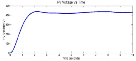
Fig-13: PV Voltage Vs Time
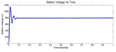
[image:6.595.318.550.602.706.2]© 2018, IRJET | Impact Factor value: 6.171 | ISO 9001:2008 Certified Journal | Page 1776 Fig-14: Battery Voltage Vs Time
Fig-14 represents battery voltage Vs time .If battery is charging more current is drawn from PV and if it is discharging, less amount of current will be drawn.
Fig-15: MPP Power graph Vs time
4. CONCLUSION
A Stand-alone Photovoltaic System for agricultural applications is actuating with the help of MATLAB/SIMULINK. Simulation results prove that the boost converter successfully tracks the maximum power point (MPP) of the solar panel and battery is charged accordingly. To get the maximum power from the PV array the Adaptive Incremental Conductance approach is utilized for actualizing the MPPT calculation Microcontroller is needed to maintain MPP and also to generate PWM signal. Battery plays here two roles. One is it acts as a load and other is it acts as an energy storage element. The results ensure an optimum and efficient model for reliable and high quality stand-alone PV system.
REFERANCES
[1] A. Mathew and A. Immanuel Selvakumar, “MPPT
based stand-alone water pumping system,” in Proceedings of the IEEE International Conference on Computer, Communication and Electrical Technology (ICCCET '11), pp. 455–460, Tamil Nadu, India, March 2011.
[2] R. Faranda and S. Leva, “Energy comparison of
MPPT techniques for PV systems,” WSEAS Transactions on Power Systems, vol. 3, no. 6, pp. 446–455, 2008.
[3] C. Liu, B. Wu, and R. Cheung, “Advanced algorithm
for MPPT control of photovoltaic systems,” in Proceedings of the Canadian Solar Buildings Conference, Montreal, Canada, 2004.
[4] D.P Hohm, M. E. Ropp, “Comparative Study of
Maximum Power Point Tracking Algorithms Using an Experimental, Programmable, Maximum Power Point Tracking Test Bed”, Photovoltaic Specialists Conference, 2000.
[5] Azadeh Safari and Saad Mekhilef, “Simulation and
[image:7.595.42.279.285.388.2]