© 2018, IRJET | Impact Factor value: 6.171 | ISO 9001:2008 Certified Journal | Page 247
Automatic Intelligent Traffic Control System
Harsh Singh Chauhan
1, Devesh Tiwari
2, Devashish
31,2,3Dept. of Electronics & Communication Engineering, IMS Engineering College Ghaziabad, U.P, India ---***---Abstract - Vehicle travel across the world is increasing,
especially in the larger urban areas. Therefore, to better accommodate this increasing demand, the traffic control algorithm needs to be simulated and optimized. In this letter, we offer the idea of traffic light control using wireless sensor network. It is a serious problem in the traffic congestion in many major cities around the world and in these cities it has become a nightmare for travelers. Traditional systems do not control variable flows coming near junctions. In addition, interconnection between adjacent traffic light systems is not implemented in the current traffic system of passage of vehicles, passage of emergency vehicles, and passage of pedestrians. This leads to traffic jams and rush towards the crowd. Sometimes the high traffic density on one side of the junction demands more green time than the standard allotted time. The system architecture is classified into three layers; the wireless sensor network, the localized traffic flow model policy, and the higher level coordination of the traffic lights agents.
Keywords—Traffic light system; microcontroller; XBee wireless communication; IR sensor; traffic density
1. INTRODUCTION
There is a goal of customizing traffic flow of people and goods in traffic research. As the number of roads increases steadily, and the resources provided by the current infrastructure are limited, intelligent control of traffic in the future will become a very important issue. However, some limitations exist for the use of intelligent traffic control, for example avoiding traffic jams is considered beneficial for both the environment and the economy, but improvement in traffic flow can lead to an increase in demand. There are many models for traffic simulation in our research, we use the IR sensor to optimize the traffic light controller in the city and pay attention to the visual monitoring developed using the PIC microcontroller. Traffic light adaptation is a complex problem.
Even for a single junction there can be no clear optimum solution, with many junctions, the problem becomes more complex, because the position of a light affects the flow of traffic towards many other lights. Another complexity is the fact that the flow of traffic varies constantly depending on the time of day, day of week, and time of year. Complexity and performance in road works and accidents is also more affected.
In order to process the input data by computer and microcontroller and finally display it on traffic light signal -
in this letter, we propose two approaches, the first method - the data / input / image from the object / subject / vehicle and in another approach - to control closed loop systems. Traditional traffic arrangements help in solving the huge loss of traffic, reducing transport problems, reducing the amount of traffic and reducing waiting time, reducing overall travel time, optimizing cars safety and efficiency, health, there is a need to upgrade to expand profits in the economic and environmental sectors. This paper proposes a simple, low cost and real-time Smart Traffic Light Control System, aimed at removing many flaws and improving traffic management. The system is based on PIC microcontroller which controls the various functions, monitors the volume and density flow of traffic through the infrared sensor (IR), and accordingly changes the light transition slot.
In addition, in one hand portable device interacts with the traffic master controller to allow proper sub-routes through Xig bee transceivers and smooth displacement of emergency vehicles through intersection.
2. INTELLIGENT TRAFFIC CONTROL SYSTEM
The design of intelligent traffic control system is an active research topic. Researchers around the world are searching for new approaches and innovative systems. Based on mathematical equations, the model is used for car waiting time at a junction, number of cars in the waiting queue, expanding cars with lane, optimum time slots for green, yellow and red lights. In fact, fitting in the actual combination of routing, in reality, interdependence between adjacent intersections causes a complex formulation with cumbersome parameters. These parameters are incidental, dangerous, dependent, and worse, it is quite impossible to find a dynamic, consistent, and convenient solution.
© 2018, IRJET | Impact Factor value: 6.171 | ISO 9001:2008 Certified Journal | Page 248
whole system could be controlled by PIC microcontroller [1-2, 4-5] or even by PLC [8-9].
To inform the traffic system about the arrival of the emergency vehicles toward the junction, they are supported by RF emitters [10-12] that send warning signals to RF transceivers disposed at every traffic light intersection. The triggering sequences of the traffic lights are modified correspondingly in order to provide a special route to the emergency vehicles. Other researchers [13] use the Global Positioning System (GPS) to communicate with the traffic light controllers and send preemption signals. The ambulance was equipped with both RF to communicate with traffic light controller and the GSM module to report to hospital doctors about the patient status and to receive messages concerning the kind of therapy or first aid recovery that should be done to the injured patient [14].
Many works [15-16] predict the density of the traffic based on image processing methodology. But these techniques require the acquisition of good images whose quality are weather dependent, especially with the rain and the fog. Other researchers use sophisticated algorithms to model the various states of the traffic such as fuzzy logic [17] and genetic algorithms [18].
Most published works are dedicated to one junction or intersection where the influence of the adjacent intersections is not examined. Thus, the situation becomes more complicated and widely dependent. Further efforts should be made to achieve complete modeling, monitoring, and control for multiple synchronized junctions.
3. SYSTEM DESIGN
Smart traffic light control system designed, in the picture, "1" in the form of "+" corresponds to a junction of directional roads 4. We check the techniques of the current system and find the most suitable tool employed. We try also to test the proposed integrated design as architecture, hardware, and software. Next step will be an extension of the suggested traffic light system to a bidirectional "+" junction with various routing configurations. Our research target involves the management of traffic light systems for multiple adjacent bidirectional roads.
The intersection in this primary work is equipped with two traffic lights of three colors, labeled A and B, associated to the car flow coming from roads 1 and 2. Two traffic lights of two colors labeled R and L are integrated to designate the right and left deviation, respectively. Two pairs of IR transmitters and receivers are mounted on either side of roads 1 and 2.
3.1Traffic light configurations
In the proposed smart traffic light system, two configurations are presented: the first arrangement allows
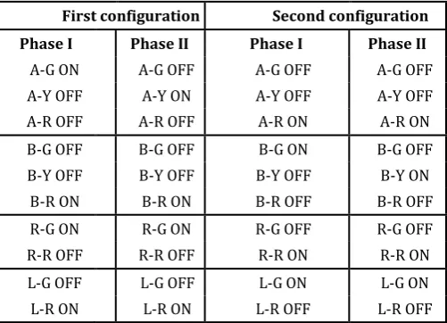
the flow of automotive from road 1 forwardly to road 3 as well as the turning to the right to follow road 4, while the second one permits the cars to move from road 2 directly toward road 4 or shift to the left to pursue road 3. The disposition of cars transitions between the roads takes into consideration the crossing of pedestrians. Table 1 illustrates the states of the traffic lights labeled A, B, L, and R during the two configuration modes. The terminology adopted is formed of three fields: traffic light-color lights states. For example, A-G ON designates that the green light of the traffic light A is illuminated. The phase I of the first configuration corresponds to the activation of the green light of the traffic light A and traffic R where the cars parking at road 1 are crossing the intersection. The phase II agrees with the warning for stop position where only the yellow light of the traffic light A is turning on for 5 s. during this configuration, the red lights of the traffic light B and L are ON. In the second configuration, the lights illuminations are reversed.
3.2Density traffic light and IR sensors
The major problem of the existing traffic light systems is that the transition timing slots are fixed within the code.
First configuration Second configuration
Phase I Phase II Phase I Phase II
A-G ON A-G OFF A-G OFF A-G OFF
A-Y OFF A-Y ON A-Y OFF A-Y OFF
A-R OFF A-R OFF A-R ON A-R ON
B-G OFF B-G OFF B-G ON B-G OFF
B-Y OFF B-Y OFF B-Y OFF B-Y ON
B-R ON B-R ON B-R OFF B-R OFF
R-G ON R-G ON R-G OFF R-G OFF
R-R OFF R-R OFF R-R ON R-R ON
L-G OFF L-G OFF L-G ON L-G ON
L-R ON L-R ON L-R OFF L-R OFF
A similar system is unable to solve the situation where the traffic congestion is only observed from one direction. This state is frequently detected in many cities where employees from outskirts are driving in the morning to the city downtown and returning home in the evening. In addition, when the flow of cars approaching the intersection roads increases during the traffic peak hours or decreases during night, the green light activation should be extended or reduced respectively. Therefore, IR transceivers mounted on either side of roads are used to detect the passage of cars through it. The IR transmitter generates continuously and regularly a 38 kHz square wave signal while the IR receiver connected to the traffic master controller receives the signal and remains inactivated. When an automobile traverses the
[image:2.595.310.561.401.582.2]© 2018, IRJET | Impact Factor value: 6.171 | ISO 9001:2008 Certified Journal | Page 249
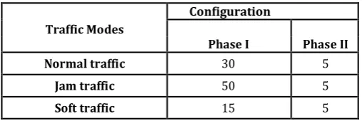
road between the IR transceivers, the IR radiation bounces and the system is activated. This activation process is analyzed by the traffic master controller where the car density counter is adjusted. Then, the traffic master controller, which is equipped with PIC microcontroller, responds to the acquired data. Actually, three modes of lighting transition slots are suggested: the normal mode, the traffic jam mode, and the soft traffic mode. The shifting between these three modes is done dynamically and in real time. In fact, the number of counted cars in the phase I of a given configuration affects directly the green light period in the next phase I of the proceeding configuration. The timing slots of the different modes are depicted in Table 2. The three timing slots associated to the normal, jam, and soft modes of traffic are respectively 30, 50, and 15 s. These levels are assigned by the code and can be adjusted by the software. For normal mode, the phase I of each configuration is equal to 30 s. However, if road 1 reveals jam traffic and road 2 shows soft traffic then the period of phase I of the first configuration will be 50 s. In contrast, the period of phase I of the second configuration will be 15 s.
It is noted that during the first configuration, the cars of road 1 are moving to their destination while the cars of road 2 are stacked and parked. Furthermore, when phase II of the first configuration starts, the IR sensor of the road 1 begins the car counting from zero.
3.3Emergency vehicles
In one of the adequate conditions in the traffic light system, the emergency vehicle route concerns the high priority through the junction of the roads. An emergency vehicle includes ambulance, rescue vehicle, fire brigade, police and VIP person, who may be caught in traffic congestion. There may be many problems with this problem which depend on the injury of the patient, person accident, firefighting, robbery and many different important situations. It is compulsory to implement a technique to solve this situation.
Traffic Modes
Configuration
Phase I Phase II
Normal traffic 30 5
Jam traffic 50 5
Soft traffic 15 5
A handheld portable device at the disposition of the traffic officer is proposed in order to command the traffic master controller. Indeed, the portable controller could be adjusted to be mounted on emergency vehicles or implemented in the traffic control center. The portable device is supported by
two push buttons labeled EA and EB. The EA button is pressed when the emergency vehicle arrives at the intersection from the side of traffic light A, that is from road 1. Due to this action, the phase I of the first configuration is set and the green light timing slot is shining unlimitedly to provide sufficient time to the stacked vehicle to traverse the intersection. Next, the EA button is pressed again to return to the normal mode, where the yellow light of the traffic light A is ON for 5 s to warn the drivers that traffic light B will be closely triggered. If the elapsed time exceeds 4 minutes and the EA button is still operating for many causes, the system is automatically actuated and initiates the second configuration. The EB button applied to the traffic light B achieves similar process. If the two buttons are pressed simultaneously, the priority is given to the button EA.
4. ELECTRONIC COMPONENTS
The circuit of the smart light traffic control system is implemented based on various electronic components that include: the Programmable Intelligent Controller (PIC) 16F877A microcontroller, an LCD display device, XBee transceivers, a pair of IR sensors, push buttons (EA, EB, and 1 to 4), and many colored LEDs that represent the three lights (red, green, and yellow) of the traffic lights A and B associated with the roads 1 and 2 as well as the two lights (red and green) for the traffic light R and L associated with the deflection to the right and left in the direction of roads 3 and 4.
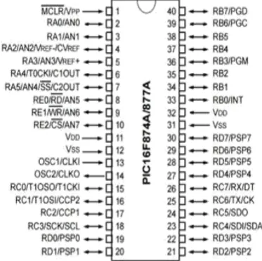
4.1Microcontroller PIC 16F877A
The PIC microcontroller PIC16f877a is one of the most renowned microcontrollers in the industry. This controller is very convenient to use, the coding or programming of this controller is also easier. One of the main advantages is that it can be write-erase as many times as possible because it use FLASH memory technology. It has a total number of 40 pins and there are 33 pins for input and output. PIC16F877A is used in many pic microcontroller projects. PIC16F877A also have many application in digital electronics circuits. PIC16f877a finds its applications in a huge number of devices. It is used in remote sensors, security and safety devices, home automation and in many industrial instruments. An EEPROM is also featured in it which makes it possible to store some of the information permanently like transmitter codes and receiver frequencies and some other related data. The cost of this controller is low and its handling is also easy. Its flexible and can be used in areas where microcontrollers have never been used before as in coprocessor applications and timer functions etc.
[image:3.595.36.290.599.684.2]Each port has its own associated TRIS register. The configuration of these TRIS registers is to select the data transfer direction between the microcontroller and the different peripheral devices through the ports. When a TRIS register is cleared, its corresponding port acts as output, otherwise it operates as input.
TABLE II. TIMING SLOTS ACQUIRED BY EACH CONFIGURATION AND ACHIEVED FOR THE
© 2018, IRJET | Impact Factor value: 6.171 | ISO 9001:2008 Certified Journal | Page 250
[image:4.595.67.254.168.354.2]On the other hand, many microcontroller port pins can be extended to perform incremental functions and operate specific purposes. The PIC microcontroller is backed up by the Universal Synchronous Asynchronous Receiver Transmitter (USART) module that permits the PIC to communicate with wide range of devices
Fig. 2. Pin configuration of the PIC 16F877A microcontroller
4.2 LCD display
Liquid Crystal Display (LCD) [24] is a power economical, tenuous, flat-panel display, simply programmable, and can be used in many digital and electronic circuits. It employs a matrix structure in which the active element forming the pixel cell is located in the intersection of two electrode buses. Particularly, the 16x2 LCD used in the implemented prototype is able to display data over 2 lines, each of 16 characters.
Actually, two types of registers are used to configure the LCD; the command register is recommended for the control instructions as LCD initialization, clearing the screen, setting the cursor position, and controlling display. While the data register holds the ASCII code of the characters that are promptly appeared on the display.
4.3 IR sensor
An infrared sensor is an electronic device implemented to detect obstacles or to differentiate between objects depending on its feature. It is generally harnessed to measure an object heat or its motion [25]. The IR sensor emits or receives the infrared radiations (430 THz – 300 GHz) that are invisible for the human eye. The LED (Light Emitting Diode) may act as an IR emitter while the IR detector is a photodiode component which is sensitive to IR light having the same frequency as the emitted radiation. The concept of operation is simple: when IR radiation of the
LED reaches the photodiode, the output voltages change according to the magnitude of the IR light
4.4 XBee transceivers
The XBee transceiver module, Series 2, allows creating complex mesh networks based on ZigBee firmware [26]. It admits a safe and simple full duplex communication between microcontrollers through serial port data transfer. The XBee features (2 mW output, 120 m range, built-in antenna, 250 kbps max data rate, and 8 digital IO pins) are suitable for our objective. Moreover, XBee is supported by point-to-point communication adequate for using one traffic light controller and corroborative also by multi-point network compatible for using multiple traffic controllers. In the XBee configuration, the component connected to portable controller runs as server whereas that linked to traffic light controller fills in the host mode. The XBee characteristics give immunity against interference from neighboring systems and avoid the interaction of closer systems which prohibit the interruption in their services.
5. HARDWARE DESIGN
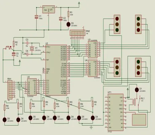
The Smart Light traffic control system is made up of two separate devices: Traffic master controller and handheld portable controller. fig 3 uses the prototypes software to show the hardware applied circuits of the Smart Traffic Controller.
The traffic master controller is mounted with the traffic lights at the roads intersection and is responsible for the lighting transition and their timing slots. Its implemented design circuit includes: the PIC 16F877A microcontroller, the three lights (red, green, and yellow) of the traffic lights A and B associated to the roads 1 and 2, the two lights (red and green) for the traffic light R and L associated with the deflection to the right and left in the direction of roads 3 and 4, the two IR receivers to measure the traffic volume, the XBee transmitter system, and other basic components. The traffic master controller provides the duration and the schedule of the two configurations and their dedicated phases for different modes of traffic. It determines the status of the different lights by commanding the triggered switches connected to the PIC ports. The microcontroller is also connected to IR detectors whose output voltages are responsible of shifting the counter of the cars arriving at the intersection. Finally, the XBee module receives the command orders form the portable controller and calls the corresponding emergency subroutines.
© 2018, IRJET | Impact Factor value: 6.171 | ISO 9001:2008 Certified Journal | Page 251
[image:5.595.36.289.187.408.2]An LCD screen is employed to notify the user if the mode of emergency is operating and which emergency procedure is currently running. We propose also a password of 6 digits formed by the combinations of 4 digits from 1 to 4 in order to supply the portable controller by a certain security level [27]. The total number of arrangements is 4096 possibilities. The role of security code is to prevent unauthorized persons from accessing to the smart light system.
Fig. 3. Block diagram of the circuit designed by Proteus software. The handheld portable controller hardware is is
disposed at left while the traffic master controller implementation is shown at the right.
6. CONCLUSIONS
Density Based Signal Management in Traffic System with emergency override shows how the Traffic Light Signal control, including with the implement of Emergency vehicle get passed through signals. The acquired data from IR Sensors reschedule the traffic light timing according to the traffic condition for low or high density road traffic. If the density of the road traffic is high then Maximum density of traffic will allow maximum default timing for traffic lights. Minimum density of traffic will allow traffic with minimum timing for traffic lights. If the traffic rate on both side is Equal or gap within traffic then according to arrival time traffic light signal set to minimized. Emergency Override can be done by Bluetooth device which keeps green signal on till the vehicle get passed up through signals. A pedestrian can cross the road by turning the switch on in the case of emergency. The designed system is implemented, realized electronically, and tested to ensure complete validation of its operations and functions. The current design can be promoted by monitoring and controlling an intersection with double roads. Future improvements can be added such as pedestrian crossing button, delay timing displays, as well as car accident and failure modes. The integration of different
traffic controllers at several junctions will be investigated in the future in order to accomplish a complete synchronization. To study the system performance, traffic data can be recorded and downloaded to computer platform where statistical data analysis studies could be applied to better understand the traffic flows between the intersections. Finally, traffic light controller could be powered by solar power panels to reduce grid electricity consumption and realize green energy operations.
REFERENCES
[1] N. Kham, and C. Nwe, “Implementation of modern traffic light control system”, International journal of scientific and research publications, Vol. 4, Issue 6, Jun. 2014.
[2] I. Isa, N. Shaari, A. Fayeez, and N. Azlin, "Portable wireless traffic light system (PWTLS)", International journal of research in engineering and technology, Vol. 3, Issue 2, pp. 242-247, Feb 2014.
[3] P. Sinhmar, "Intelligent traffic light and density control using IR sensors and microcontroller", International journal of advanced technology & engineering research (IJATER), Vol. 2, Issue 2, pp. 30-35, March 2012.
[4] E. Geetha, V. Viswanadha, and G. Kavitha, "Design of intelligent auto traffic signal controller with emergency override", International journal of engineering science and innovative technology (IJESIT), Vol. 3 , Issue 4, pp. 670-675, July 2014.
[5] G. Kavya, and B. Saranya, "Density based intelligent traffic signal system using PIC microcontroller", International journal of research in applied science & engineering technology (IJRASET), Vol. 3, Issue 1, pp. 205-209, Jan 2015.
[6] A. Dakhole, M. Moon, "Design of intelligent traffic control system based on ARM", International journal of advance research in computer science and management studies, Vol. 1, Issue 6., pp. 76-80, Nov. 2013.