674
Complexity Reduction Area Efficient BCH Code
for NAND Flash Memory
Ms.C.Gayathri1,P.Mozhiarasi2
1
Assistant Professor,2Student (ME VLSI DESIGN), Electronics and Communication Engineering
1,2Sri Eshwar College of Engineering,Coimbatore, Tamilnadu
Abstract-There is a tremendous demand for digital transmission and storage systems due to the increase in development of communication in which data is transferred from transmitter side to receiver side at a faster rate with less time. Even though the time consumption is reduced, there is a chance of occurring errors due to multipath propagation. In order to control these errors Error Correcting Codes (ECC) was invoked, which includes variety of codes depending on application. One of the simplest and first block code is Hamming codes which are capable of correcting only one random error and they are not practically useful. So in this paper, Bose, Chaudhuri and Hocquenghem (BCH) codes form a large class of powerful random error-correcting cyclic codes which can correct multiple errors.Inaddition with BCH, the NAND Flash memory is used to store codeword, and makes for correction part in decoder side where the error is corrected effectively. The enhanced (15, 5, 3) BCH code using hardware description language called VHDL and synthesized in Xilinx 13.2 version.
Key words-Berlekamp Massey Algorithm (BMA), Bose, Chaudhuri and Hocquenghem(BCH), Chein Search (CS), Error Correcting Codes (ECC),Syndrome Calculation(SC)
I. INTRODUCTION
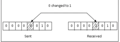
[image:2.612.207.404.421.491.2]Binary information can be transmitted from one device to another by electric wires or other communication medium. A system that cannot guarantee that the data received by one device are identical to the data transmitted by another device is essentially useless.Yet anytime data are transmitted from source to destination, they can become corrupted in passage.Many factors, including external noise, may change some of the bits from 0 to 1 or vice versa which is illustrated in Fig. 1.
Fig. 1 Error occur during Binary Data Transmission
Binary information/data is transmitted as electromagnetic signal over a channel whenever an electromagnetic signal flows from one point to another; it is subjected to unpredictable interference from heat, magnetism and other forms of electricity. This interference can change the shape or timing of signal.If the signal is carrying encoded binary data, such changes can alter the meaning of data. The purpose of error detection code is to detect such bit reversal errors. Error detection uses the concept of redundancy which means adding extra bits for detecting errors at the destination.
II. MODIFIED TECHNIQUES
A. Nand Flash Memory In Bch Codes
Technology (IJRASET)
drives (SSD) and various memory cards that are designed today use NAND technology.Fig. 2 NAND Flash Memory Cell B. BCH Codes
In coding theory, the BCH codes form a class of cyclic error correcting codes that are constructed using finite fields. BCH (Bose ChaudhuriHocquenghem) code is defined by
Codeword length, n = 2m-1
Number of parity check bits, n-k ≤ mt
Minimum distance, dmin≥ 2t+1
where, m– primitive polynomial k– message length
t – maximum number of correctable errors
A codeword(c0, c1, ..., cn-1) of a cyclic code can be represented as the polynomial c(x) = c0 + c1x+ .... + cn-1xn-1 .
The generator polynomial of a t-error-correcting BCH code is defined to be the least common multiple (LCM) of f1, f3, ... f2*t-1,
that is,
g(x) = LCM{ f1, f3, f5, ... f2*t-1}where, fj is the minimal polynomial of j (0 < j < 2t + 1).
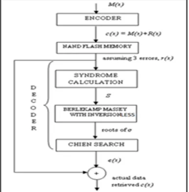
In encoder stage, the message bit is padded with zeroes which is then divided with the g(x) to obtain the remainder which is known as redundant bit(R(X)). If remainder is zero then no error in codeword otherwise error (Syndrome) is present. The decoder has three stages namely Syndrome calculation, Berlekamp Massey Algorithm and Chien Search. This syndrome calculation operates over Galois Field (GF) which is also known as Finite Field using TABLE I.
676
Consider m=4, n=2m -1= 24-1=15, k=5, t=3, dmin =2t+1=2(3)+1=7. The generator polynomial g(x) is obtained by finding roots
of polynomial P(x) of degree m which is primitive if and only if smallest integer n for which p(x) divides xn+1. Here addition is performed by modulo 2-addition.
P(x) =(x15+1)
=(x+1) (x4+x+1)(x10+x9+x8+x6+x5+x2+1) (1)
By inversing the root q(x) in (1), generator polynomial g(x) will become x10+x8+x5+x4+x2+x+1.
Let fi(x),i= 1,2,3,…,2t be the minimal polynomial, then g(x)= LCM{f1(x),f2(x),f3(x),…,f2t(x)}. But, g(x) is simplified to g(x) =
LCM{f1(x),f3(x),f5(x),…,f2t-1(x)} because every even power of primitive element will have same minimal polynomial as some odd
power of the elements having the number of factors in the polynomial. Therefore, g(x) = LCM{f1(x),f3(x),f5(x)}where, f1(x) =x
4
+x+1, f3(x) = x 4
+x3+x2 +x+1, f5(x) = x 2
[image:4.612.199.414.283.485.2] [image:4.612.210.407.531.664.2]+x+1.
TABLE IGF(16) generated with Primitive polynomial x4+x+1
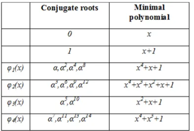
The minimal polynomial can be obtained by using conjugate roots as mentioned in TABLE II.
TABLE II Minimal Polynomials of the element in GF(16)
Those conjugate roots can be found by using , , , where i=1,2,3,….
1) BCH Encoder p( x)
Technology (IJRASET)
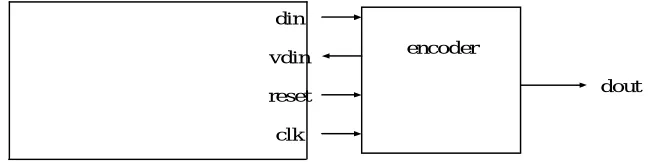
The input/output interface of the re-encoder consists of the following signals:a) reset (input)- to (synchronously) reset the encoder and synchronise the encoder with the decoder b) din (input)- the data input
c) dout (output)- the encoded data to be transmitted along the potentially noisy channel d) clk (input)- the clock signal to clock both the input information and theencoded data e) vdin (output)- a valid data in signal.
The encoder input/output interface of the re-encoder is shown in Fig. 4
encoder din
vdin
clk
[image:5.612.81.405.198.279.2]reset dout
Fig. 4The Input /Output Interface of the Encoder
In initial stage, the message polynomial (M(x)) is padded with (n-k) zero bits to form Xn-k M(x). Xn-k M(x) = X15-5M(x) = X10 M(x)
= M + 0000000000 (2)
From (2)Xn-k M(x) mod g(x) is computed, the remainder polynomial(R(x)) is obtained which should be appended with the message polynomial (M(x)) to produce the codeword(c(x)) i.e., c(x) = Xn-k M(x) + R(x). This codeword is then stored in flash memory, later for correction purpose in decoder stage. These encoder procedure is illustrated by considering M(x) = 10001.
Therefore,
Xn-kM(x) = X10 M(x) = 100010000000000. (3)
Dividing (3) by g(x) we obtain remainder polynomial R(x) = 1110101100 which is then appended with X10 M(x).
c(x) = 100011110101100 (4)
Thus, codewordc(x) is obtained finally which is represented in (4).
2) BCH Decoder
The input/output interface of the decoder consists of the following signals:
a) reset (input)- to (synchronously) reset the decoder and synchronise it with the encoder b) din (input)- the input data
c) dout (output)- the corrected data
d) clk (input)- the clock signal to clock both the received data and the output data
f) vdout (output)- a valid data out signal. A high level on this signal indicates that dout should be clocked with clk. The input/output interface of the decoder is presented in Fig. 5
decoder din
reset
clk
dout
vdout
©IJRASET 2015: All Rights are Reserved
678
Fig. 5 TheInput/Output Interface of the Decoder
a) Syndrome Calculation (SC) Let
c(x)= c0 + c1x + c2x 2
+ ... + cn-1x n-1
r(x) = r0 + r1x + r2x2 + ... + rn-1xn-1 (5)
e(x) = e0 + e1x + e2x2 + ... + en-1xn-1 be the transmitted polynomial, the received polynomial and the error polynomial
respectively so thatr(x) = c(x) + e(x)from (5)
1 0 1 0 1 0)
(
n i n i j i i j i i n i j i i ij
c
e
c
e
S
(6)To generate the syndromes, express (6) as
Sj = (...((rn-1 * j + rn-2) * j + rn-3) * j + ....) * j + r0.
Thus a circuit calculating the syndrome Sj carries out (n-1) multiplications by the constant value j
and (n-1) single bit summations in equation (2.12). Note that because rjGF(2) the equation S2i = Si2 is met.
Let us consider c(x) with 3 errors (t = 3) and represent them as r(x) i.e., when noise is added in the channel while transmitting the data to the receiver. At the receiver side, let us assume r(x) = 110010110100100. The number of syndrome elements is 2*t = 6, to find t=3 errors. Those syndrome elements are represented as S1, S2, S3, S4, S5,S6 in (7).
S1(x) = r(x) mod f1(x)
S2(x) = r(x) mod f2(x) = r(x) mod f1(x)
S3(x) = r(x) mod f3(x) (7)
S4(x) = r(x) mod f4(x) = r(x) mod f1(x)
S5(x) = r(x) mod f5(x)
S6(x) = r(x) mod f6(x) = r(x) mod f3(x)
By the property of Field element several powers of generating element will have the same minimal polynomial (fromTABLE II) when f(x) is polynomial over GF(2), α is an element ofGF(2m). Thus, syndrome polynomial can be represented as
S(x) = S1x + S2x 2
+ S3x 3
+…+ S2tx 2t.
Therefore, S1(α) = α12, likewise S2(α2), S3(α3), S4(α4), S5(α5), S6(α6) syndromes can be calculated.
If the remainder equals zero, then it is declared that no error in the codeword or else error(S) is present. So this error will be a seed for decoding the codeword and to find error location.
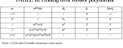
b) Berlekamp Massey Algorithm (BMA)
Technology (IJRASET)
TABLE III Finding error locator polynomialThe “Key Equation” is given by
(i) ( )( ) = ( ) + ( ) ( )( )
(ii) = = deg ( )( ) (8)
(iii) = + ( ) + ( )
+⋯+ ( )
Thus, the Key Equation (8) provides known number of coefficients of generating function to determine remaining coefficients of the polynomial.
c) Chien Search (CS)
The last step in decoding BCH codes is to find the error location numbers. These values are the reciprocals of the roots of (x) and may be found simply by substituting 1, , 2, ... , n-1 into (x).
The roots of (µ)( ) in GF (24
) should be found out by following order.
If (µ)( ) = ( )( )= α25
x3+ α5 x2+ α12x+1 = 0 is obtained by substituting x = 0, 1, α, α2,α3, α4, α5, α6, α7, α8, α9, α10,α11,α12,
α13, α14.Therefore, α2, α6, α12are the roots for ( )( )= α25x3+ α5 x2+ α12x+1. The bit position of error location will be the inverse of their roots (α2, α6, α12) i.e., 010001000001000
Thus, the error pattern polynomial can be written as e(x) = x13 + x9+ x3. And actual data is recovered by performing mod-2 addition for r(x) and e(x).
c(x) = r(x) + e(x)
=110010110100100+010001000001000
=100011110101100 (9)
Therefore, (9) represents the recovered data without any error.
III. SIMULATION RESULTS
The software used to develop programs are Xilinx. The VHDL code for (15,5,3) binary BCH re-encoder and decoder are simulated on Xilinx 13.2i simulator and synthesizer. The simulation waveform for (15,5,3) BCH Re-Encoder, BCH Decoder are shown in Fig. 6 and 7. The waveform simulation has a clock period of 10ns.
680
Fig. 6Simulation Waveform of BCH Re-Encoder
[image:8.612.197.415.224.311.2]In Fig. 6 the clock is set high, which is used to clock the encoded data. The input information data is set to ‘1’. To synchronize the encoder with decoder the reset signal is used. The input data (din) is set and the encoded output data (dout) is obtained.
Fig. 7 Simulation Waveform of (15,5,3) BCH Code
In Fig 7, shows the waveform for (15,5,3) BCH code where data input is given and decoded data is obtained using c(i) registers. These c(i) registers are used to store the values of error locator polynomial.
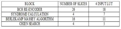
TABLE IV Performance Analysis of (15,5,3) BCH Code
From TABLE IV, the performance analysis in terms of slices and LUTs which is done through the simulation.
IV. CONCLUSION AND FUTURE WORK
The error correcting technique plays an important role in modern communication system. At first, each character in a text message is transformed to a binary data. (15, 5)BCH encoder and decoder are designed, and it detects and corrects 3 errors by using Berlekamp Massey Algorithm (BMA) and Chien Search (CS) which can be implemented using hardware description language (HDL) known as VHDL and synthesized by Xilinx ISE 13.2 simulator. From the simulation, the performance analysis is done and observed that the enhanced BCH code reduces the area in terms of slices and LUTs which in turn simplify the computational scheduling of the syndrome and Chien search leading to high throughput.
The future work includes: The 15 bit codeword length (n) and 5 bit message length (k) may correct upto three errors (t) while transmission of data. But upto 3 correctable error technique is not enough for real time applications. Due to this reason, the codeword length (n) can be increased along with them a newalgorithm is adopted instead of Berlekamp Massey Algorithm in the next step design.Thus,decoding latency and also complexity can be reduced and can be implemented in Spartan 3 FPGA.
REFERENCES
[1] Arul K. Subbiah and SomnathViswanath (Feb. 2010), “Evolving throughput driven architecture for error correction in NAND memory”, Arasan Chip Systems Inc. White Paper.
[2] Berlekamp.E.R (1968), “Algebraic Coding Theory”, McGrawHill, New York.
[3] W.W.Peterson, “Encoding and error-correction procedures for the Bose-Chaudhuri Codes”, IRE Trans. Inf. Theory, September 1960.
[4] Hyojin Choi, Wei Lin, and Wonyong Sung (May 2010), “VLSI implementation of BCH error correction for multilevel cell NAND flash memory”, IEEE Trans. Very Large Scale Integr. (VLSI) Syst., vol. 18, no. 5, pp. 843–847.
[image:8.612.203.409.396.446.2]