5
IV
April 2017
Technology (IJRASET)
Internal Flow Analysis of Submersible Pump
Impeller using Computational Fluid Dynamics
K. Manikandan 1, L. Periyannan2 1
PG Scholar, 2AP, Department of Mechanical Engineering Mahendra Engineering College Namakkal, TN, India
Abstract: Submersible pump has been playing an important role in industrial and house hold applications. A submersible pump (or electric submersible pump (ESP)) is a device which has a hermetically sealed motor close-coupled to the pump body. The whole assembly is sub merged in the fluid to be pumped. The submersible pumps used in ESP installations are multistage centrifugal pumps operating in a vertical position. The liquids, after being subjected to great centrifugal forces caused by the high rotational speed of the impeller, lose their kinetic energy in the diffuser where a conversion of kinetic to pressure energy takes place. And thus in this pump impeller plays an important role by which the efficiency has been calculated.In an impeller the design parameters such as number of blades, blade angles, diameter of the impeller, width of the blades are the important parameter to be considered because which affects the performance of the pump. And so here we made an analysis on the impeller by changing the outlet blade angle from the existing blade. The analysis is made by using Computational Fluid Dynamics (CFD) software by which the hydraulic efficiency has been calculated. The results are obtained from the Computational Fluid Dynamics (CFD) it has been calculated that by increasing the outlet blade angle by 50 the hydraulic efficiency of the impeller has been increased by 9.85% from existing impeller model which has the hydraulic efficiency of 73.5%. It has been evident that by increasing the blade angle the hydraulic efficiency is increased. For each impeller, the flow pattern and the pressure distribution in the blade passages are calculated and finally the head-capacity curves are compared and discussed.
Keywords: ANSYS, Hard Chrome, Thermal Boundary
I. INTRODUCTION
A. Submersible Pumps
The submersible pumps used in Electric submersible pump installations are multistage centrifugal pumps operating in a vertical position. Produced liquids, after being subjected to great centrifugal forces caused by the high rotational speed of the impeller, lose their kinetic energy in the diffuser where a conversion of kinetic to pressure energy takes place. This is the main operational mechanism of radial and mixed flow pumps.
B. The Centrifugal Impeller
The fluid enters at centre of the wheel, turns through a right angle and, as it moves outwards radially, is subjected to centrifugal force resulting in an increase in its static pressure. Rotational and radial components of velocity are imparted to the fluid. The corresponding outlet velocity pressure may then be partially converted into static pressure.
II. IMPELLER MODEL AND ITS SPECIFICATIONS
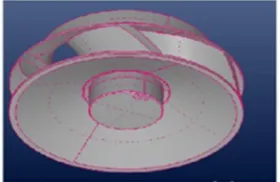
[image:2.612.237.377.612.703.2]The impeller model and their specification is given by the Hari Industries is given below:
Technology (IJRASET)
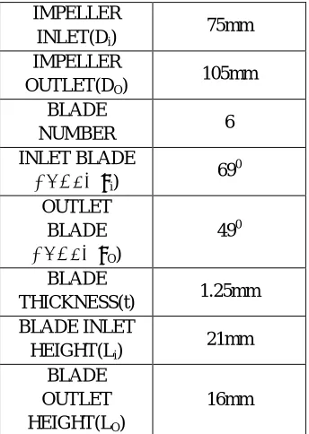
TABLE I Impeller parameters:
As for the existing impeller model, an design optimisation has been planned by changing their number of blades(n), Inlet blade
angle(α) and Outlet blade angle (β) using CFD software in terms of Trial and Error method and kept the other specifications as to be constants.
III. METHODOLOGY
In all of these approaches the same basic procedure is followed.
A. During preprocessing
B. The geometry (physical bounds) of the problem is defined.
C. The volume occupied by the fluid is divided into discrete cells (the mesh). The mesh may be uniform or non-uniform. D. The physical modeling is defined.
E. Boundary conditions are defined. This involves specifying the fluid behaviour and properties at the boundaries of the problem. For transient problems, the initial conditions are also defined.
F. The simulation is started and the equations are solved iteratively as a steady-state or transient. G. Finally a postprocessor is used for the analysis and visualization of the resulting solution.
IV. SOFTWARE ANALYSIS MODEL
[image:3.612.221.393.93.335.2]Analysis for Existing Impeller - Static pressure (Pascals), relative velocity magnitude (m/s), Velocity Vector
Fig 2 Analysis for Existing IMPELLER
INLET(Di)
75mm
IMPELLER
OUTLET(DO)
105mm
BLADE
NUMBER 6
INLET BLADE
ANGLE(βi)
690
OUTLET BLADE
ANGLE(βO)
490
BLADE
THICKNESS(t) 1.25mm
BLADE INLET HEIGHT(Li)
21mm
BLADE OUTLET
HEIGHT(LO)
Technology (IJRASET)
V. RESULT AND DISCUSSIONS
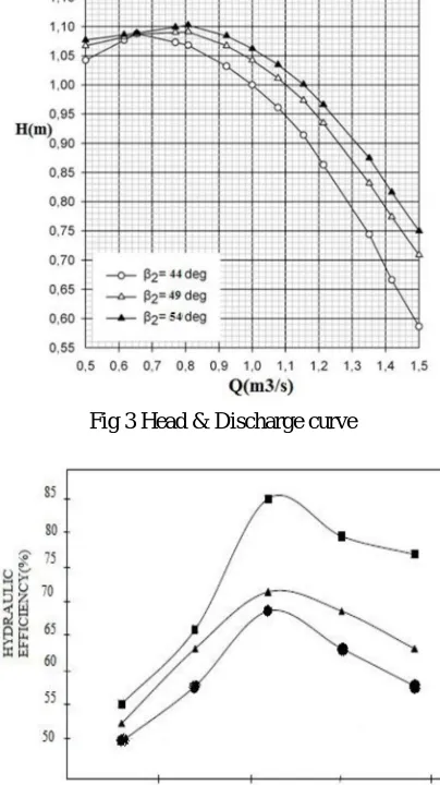
[image:4.612.210.402.128.317.2]In this graph we can find that at 540 outlet blade angle the discharge and head will be maximum when compared to the outlet blade angle 440 and 490. Hence it is conclude that at 540 angle the head and discharge will be higher than the other angles 440 and 490. Various results are shown in the following figures.
Fig 3 Head & Discharge curve
Fig 4 Hydraulic Efficiency & Discharge
VI. CONCLUSION
[image:4.612.204.406.132.492.2]Technology (IJRASET)
REFERENCES
[1] Manivannan, “Computational fluid dynamics analysis of a mixed flow pump impeller” International journel of science and technology Vol. 2, No. 6, 2010, pp. 200-206
[2] Khalid. S. Rababa, The Effect of Blades Number and Shape on the Operating Characteristics of Groundwater Centrifugal Pumps . European Journal of Scientific Research ISSN 1450-216X Vol.52 No.2 (2011), pp.243-251
[3] E.C. Bacharoudis, A.E. Filios, M.D. Mentzos and D.P. Margaris, Parametric Study of a Centrifugal Pump Impeller by Varying the Outlet Blade Angle. The Open Mechanical Engineering Journal, 2008, 2, 75-83
[4] LIU Houlin*, WANG Yong, YUAN Shouqi, TAN Minggao, and WANG Kai, Effects of Blade Number on Characteristics of Centrifugal Pumps, Chinese Journal of Mechanical Engineering Vol. 23,2011.
[5] Christopher Earls Brennen “Hydrodynamics of Pumps” by OPEN © Concepts NREC 1994. [6] Yunus A.Cengel and John M.Cimbala “ Fluid Mechanics ”
[7] D. Eckardt, “Detailed flow investigations within a high-speed centrifugal compressor impeller”, ASME Journal of Fluids Engineering, vol. 98, pp. 390-402, 1976