Design & Study of Microstrip Patch Antenna for
Wireless Applications Using HFSS
Jagadeesha S1, Ambresh P A2, Sharanappa.C3, Bharath Raj M4
1
Assistant Prof, ECE, S D M. Institute of Technology, Ujire Karnataka. India.
2
Assistant Prof, Electronics department 3, Mangalore University, Karnataka. India.
3
Assistant Prof, Physics department 3, J .T College, Gadag, Karnataka. India.
4
Assistant Prof, ECE, S D M. Institute of Technology, Ujire Karnataka. India.
Abstract: Antenna the key element in wireless communication devices has undergone amazing developments especially in the direction of compactness and broad bandwidth. It is found that the incorporation of a slot in the patch can provide a flat input resistance and a linear input reactance across a wider bandwidth of about 25.86%with equivalent gain of 2.8dB.
Keywords: Patch, antenna, Frequency, wireless, HFSS.
I. INTRODUCTION
To support the high mobility necessity for a wireless telecommunication device, a small and light weight antenna is likely to be preferred. For this purpose Compact Microstrip antenna is one of the most suitable application. The development of antenna for wireless communication also requires an antenna with more than one operating frequency. This is due to many reasons, mainly because there are various wireless communication systems and many telecommunication operators using various frequencies. Therefore one antenna that has multiband characteristic is more desirable than having one antenna for each frequency band [1].Microstrip antenna structures are most common option used to realize millimeter wave monolithic integrated circuits for microwave, radar and communication purposes. The shape and operating mode of the patch are selected, designs become very versatile in terms of operating frequency, polarization, pattern and impedance [2]. Using a rectangular slot in the radiating patch increases the upper-edge frequency, and it is possible to control this frequency by adjusting the slot width. By cutting a modified slot of suitable dimensions at the radiating patch a new fed configuration can be constructed [3].Dielectric material of the substrate ( εr) selected for this design is FR-4 Epoxy which has a dielectric constant of 4.4 and loss tangent equal to 0.002. The dielectric
constant of the substrate material is an important design parameter. Low dielectric constant is used in the prototype design because it gives better efficiency and higher bandwidth, and lower quality factor Q. The low value of dielectric constant increases the fringing field at the patch periphery and thus increases the radiated power [4].The effect of very high operating frequency in GHz range which increases chances calculation error in the model. The proposed antenna in this paper can be used for broadcasting, remote sensing, aeronautical radio navigation and mobile satellite applications [5].Conventional Microstrip patch antenna designs with thick substrate layer causes major problem associated with impedance matching. The proposed antenna is designed on RT Duroid 5880 substrate material which is low density, high weight material for high performance weight sensitive applications. The very low dielectric constant of RT/duroid 5880 laminates is uniform from panel to panel and is constant over a wide frequency range. Applications include airborne antenna system, light weight feed network, military radar systems, missile guidance system and point to point digital radio antennas [6].
II. ANTENNADESIGN
The dielectric constant of the substrate is closely related to the size and the bandwidth of the microstrip antenna. Low dielectric constant of the substrate produces larger bandwidth. The resonant frequency of microstrip antenna and the size of the radiation patch can be similar to the following formulas while the high dielectric constant of the substrate results in smaller size of antenna. The proposed structure of the antenna is shown in Fig. (1).Antenna is simulated on an FR4 Gloss epoxy substrate with a permittivity constant Ɛr=4.4 and relative loss tangent 0.0245. The thickness of the substrate is 3.2mm, area of the antenna is (10.85X15.739)
Which is suitable for DSRC Dedicated Short Range Communications (DSRC) is an open-source protocol for wireless communication, similar in respect to Wi-Fi.
Fig.1a Geometry of Reference Antenna (simulated) Fig. 1b Optimized Geometry of Slotted Antenna (simulated)
Fig.2a Geometry of Reference Antenna (Fabricated) Fig. 2b Optimized Geometry of Slotted Antenna (Fabricated)
III.RESULTSANDDISCUSSION
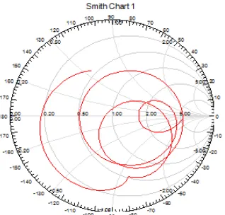
The proposed design has been simulated using HFSS simulation package that’s characteristic of the Slotted L shaped microstrip patch Antenna in terms of Return loss and its impedance bandwidth is synthesized and analysed through smith chart.
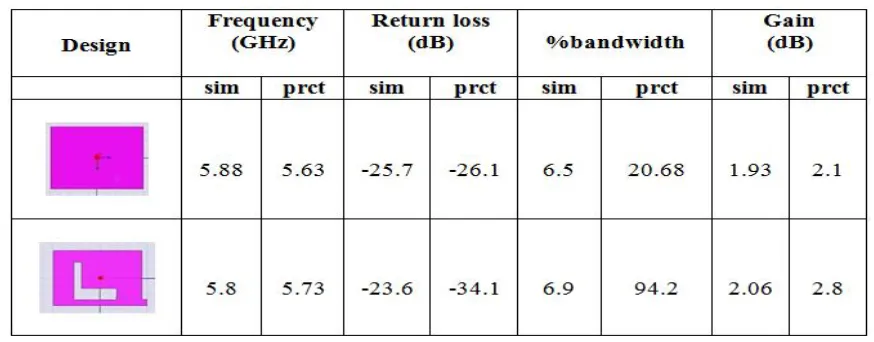
Practical results are in good agreement with simulated results. Results are verified through analysed through vector network make Agilent technology E8363C (40GHz), characteristics of above are depicted in Fig. 3 and Fig 4. Comparisons of results for reference and L shaped slotted antenna in terms of bandwidth, return loss and gain are summarized in Table1. Figure 5 and 6 shows the impedance matching of reference antenna and L-slotted antenna depicting good impedance matching characteristics.
[image:4.612.104.274.315.490.2] [image:4.612.309.502.324.484.2]Fig 4a Simulated Return loss of L slotted antenna Fig 4b Practical Return loss of L slotted antenna
Fig. 5a Smith chart of Reference Antenna (Simulated) Fig. 5b Smith chart of Reference antenna (Practical)
[image:4.612.77.236.534.686.2] [image:4.612.306.494.551.689.2]TABLE 1 Antenna parameters (Practical and simulated)
It is tested using Power Network Analyzer. Antenna design is worked out at a frequency ranging from 5.7GHz to 5.9 GHz. When tested practically is approximately matching with design specification.
IV.CONCLUSION
The design of microstrip antenna with improved bandwidth of 25.86 % and a gain of 2.8 dB is achieved which is suitable for practical wireless application. Practical and simulation study is conducted using HFSS simulation software and the results are nearly well matched with each other for better operation in wireless band.
REFERENCES
[1] U. Chakraborty S. Chatterjee& S. K. Chowdhury “A compact microstrip patch antenna for Wireless Communication”Progress In Electromagnetics Research C,
Vol. 18, 211-220, 2011.
[2] Atser A. Roy, Joseph M. Môm, Gabriel A. Igwue “Enhancing the Bandwidth of a Microstrip Patch Antenna using Slots Shaped Patch” American Journal of
Engineering Research (AJER), Vol. 02, Issue-09, p.23-30, 2013.
[3] Govardhani Immadi1, K. Swetha2 ,M.Venkata Narayana3,M.Sowmya4 “Design of microstrip patch antenna for WLAN applications using Back to Back
connection of Two E-Shapes” International Journal of Engineering Research and Applications (IJERA), Vol.2, Issue 3, May-June 2012, PP. 319-323.
[4] Rectangular Microstrip Patch Antenna Using Coaxial Probe Feeding Technique to Operate in S-Band “International Journal of Engineering Trends and
Technology (IJETT) - Volume4Issue4- April 2013.
[5] Settapong Malisuwan, Jesada Sivaraks, Navneet Madan, and Nattakit Suriyakrai “International Journal of Computer and Communication Engineering, Vol. 3,
No. 6, November 2014.
[6] K.V.L.Bhavani, B.T.P.Madhav, P.Poorna Priya, “Design of Compact U-Slot Circular Patch Antenna on RT DUROID 5880 Substrate”International Journal of