304
TRUE COLOR IMAGE ENCRYPTION BASED ON DNA
SEQUENCE, 3D CHAOTIC MAP, AND KEY-DEPENDENT
DNA S-BOX OF AES
ASHWAK ALABAICHI
Sciences College, University of Kerbala Kerbalaa - Iraq
[e-mail: [email protected]]
ABSTRACT
Digital image encryption techniques play crucial roles in preventing unauthorized accsess. In this study, color image encryption and decryption are performed through a technique that applies a 3Dchaotic map, DNA sequence, and the key-dependent DNA S-box of the Advanced Encryption Standard (AES) to get higher security. This technique comprises five steps: block transcription, encoding of DNA base, reverse/ reverse complement of DNA, use of a 3D chaotic map, and key-dependent DNA S-box of AES. In the proposed scheme, block transcription is performed to shuffle image pixels by changing their positions in the image. Encoding of DNA base and reverse/reverse complement of DNA are conducted to change pixel values, thereby diffusing the image. 3D chaotic map is then utilized to generate a secret key for shuffling A and diffusing the pixels of an image. The S-box of AES is scrambled by changing the coordinate values of the DNA box of AES to keep it obscured. Then, the image is substituted into the key-dependent DNA S-box of AES. The aforementioned processes aim to satisfy the high-level security requirement of certain encrypted images. The proposed algorithm is comprehensively tested using different criteria, such as the Number of Pixels Change Rate (NPCR), the Unified Averaged Changed Intensity(UACI), the Correlation Coefficient(CC), Information Entropy (IE), histogram, Mean Square Error (MSE), and key sensitivity analysis. Result shows that the proposed algorithm satisfies all the aforementioned criteria, thereby indicating that it is resistant to different types of attacks, including differential, statistical, and exhaustive attacks.
Keywords
:
Chaotic map, block transcription, encoding of DNA base, reverse and reverse complement of DNA, 3D logistic map, 3D Chebyshev map, key-dependent DNA S-box of AES, NPCR, UACI, CC, IE, histogram, MSE, and key sensitivity analysis.1. INTRODUCTION
Computer networks have changed the manner in which people communicate at present. For example, people can now easily transfer various multimedia files through networks. Among
information vectors in multimedia
communication, digital image is one of the greatest significant. Image communication plays a crucial role in information transmission. Accordingly, image encryption has been drawing increasing attention. Traditional encryption algorithms, such as Triple-Data Encryption Standard(3DES), International Data Encryption Algorithm(IDEA), AES, and other symmetric ciphers that were developed for textual information, are unsuitable for image encryption because of certain inherent characterstic of images, such as high pixel correlation and
redundancy. Consequently, novel image
encryption algorithms are urgently required [1-3].
305 particularly from the modern cryptographical perspective. Consequently, novel and safe cryptosystems should be established to guarantee information protection. DNA computing has entered the field of cryptography given the massive parallelism, huge storage, and ultra-low power consumption of DNA molecules. Several image encryption schemes that combine chaos and DNA computing have been proposed [1],[3-5].
The S-box is the foundation of recent symmetric algorithms, and an important part in the structure of any block symetric system. For the serial application of confusion and diffusion, many block ciphers using the traditional Shannon idea. Confusion is generally provided by some forms of substitution, i.e., “S-boxes,” and S-boxes cause nonlinearity in cryptosystems. Any form of weakness in S-boxes can lead to unsafe cryptography [6-8].
Although AES and Data Encryption Standard (DES) are ineffective for image encryption, the S-box concept of AES can be useful in the substitution process for image encryption [33]. A key-dependent S-box indicates that the S-box is changed every round based on the key and the number of rounds. The design of fixed S-boxes enables them to resist differential and linear cryptanalyses; nevertheless, key-dependent S-boxes can better resist the aforementioned attacks [9-11].
A true color image encryption algorithm is suggested in this study. To satisfy high security requirements, this scheme combines three important concepts, namely, 3D chaotic map, DNA, and the key-dependent DNA S-box of AES. The remaining parts of this paper are organized as follows. The section 2 presents related works, including recent studies. Section 3 defines a chaotic map and then illustrates its properties that are related to cryptography and its types. Section 4 defines DNA and its most prominent properties, such as DNA encoding, complementarity, and operations. Section 5 provides a brief explanation of the S-box of AES and the important key-dependent S-box. Section 6 elucidates the suggested algorithm in detail. Section 7 presents several results of the suggested algorithm. Section 8 provides the analysis of the proposed algorithm according to several factors. Finally, section 9 concludes the study and recommends topics for future work.
2. RELATED WORKS
Numerous studies have proposed algorithms based on the combination of DNA and chaotic map. Paul, Dasgupta, Naskar, and Chaudhuri in [12] presented a novel image encryption system based on a hybrid model that comprised chaotic logistic maps, DNA masking, and DNA replacement algorithm. The important benefit of this system is the improved characteristic of DNA masks for obtaining the most compatible mask with plain images. Their investigational results indicated that their presented approach demonstrated excellent encryption capability and resisted several typical attacks.
Chai et al. in [5] developed a novel algorithm for image encryption using DNA sequence operations and chaotic systems by adopting the encryption schema of permutation and diffusion. Two chaotic systems, namely, the 2D
logistic-adjusted sine map and a new 1D chaotic system,
were used to generate chaotic sequences. The initial values and system parameters of these systems were computed via the 256-bit hash value of the plain image. Their experimental and security analyses results demonstrated that their developed algorithm was sufficiently secure to resist known attacks.
Al-Mashhadi and Abduljaleel in [13] established a new hybrid encryption image mechanism that utilized triangular scrambling, DNA encoding, and a chaotic map. The scheme used a master key with a length of 320 bit and produced a group of sub-keys with two lengths (32 bits and 128 bits) to encrypt blocks of images. Then, a new triangular scrambling method was adopted to increase image security. Their experimental results were analyzed and compared with those of others algorithms. The comparison result showed that the proposed algorithm is extremely strong against attacks.
To realize the scrambling position transformation of image pixels and the spread of pixel values, Niu, Zhang, and Han in [14] suggested an efficient image encryption method on dependent hyperchaos mapping and DNA sequence library arithmetic. A safety analysis showed that their proposed algorithm effectively resisted plaintext, differential, and statistical attacks. Furthermore, their algorithm provided a large key space and high security.
306
and diffusion steps were performed
simultaneously for any pixel to reduce sending process time. The permutation step used a chaotic map and DNA to permute a pixel, whereas diffusion applied a DNA sequence and a DNA operator to encrypt a pixel. Experiments and wide security analyses were performed to show the feasibility and validity of the suggested image encryption algorithm.
Song and Qiao in [2] established a new image encryption algorithm using DNA encoding and spatiotemporal chaos. In this algorithm, an image was initially diffused through bitwise exclusive-OR (Xexclusive-OR) operation. Subsequently, the diffused image was encoded using the DNA mapping rule. Then, the rows and columns of the DNA-encoded image were confused via the spatiotemporal chaotic system. Their experiment results showed that the suggested algorithm exhibited high key sensitivity and a large key space; moreover, it could resist various attacks, such as brute force, entropy, differential, chosen-plaintext, known-chosen-plaintext, and statistical attacks. Mokhtar, Gobran, and El-Badawy in [16] developed an image encryption algorithm based on DNA and a chaotic logistic map. The map was used to confuse and diffuse the pixels of an image. Then, DNA sequence was applied as a one-time pad to change the values of the pixels in the image. The proposed algorithm could efficiently resist statistical and differential attacks.
Jain, Agarwal, Jain, and Singh in [17] proposed a symmetric image encryption algorithm based on DNA S-box and chaotic sequence. Their proposed algorithm included two parts. First, the unique DNA-based S-box performed substitution on the DNA-encoded image. Second, confusion was achieved by shuffling the rows and columns of the cipher-based chaotic map. Their proposed technique was then analyzed in terms of brute force attack, key space analysis, and statistical analysis. Satisfactory results were obtained. Zhang et al. in [4] presented a novel image encryption schema by DNA coding, central dogma, and their combination with the 3D Vigenere cipher and logistic map. DNA coding and the genetic central dogma were carried for image coding and shuffling in the presented scheme, whereas the Vigenere cipher and chaotic system were used to enhance the security of the schema. The presented schema exhibited a large secret, key space, and high secret key sensitivity. Moreover, it could effectively resist exhaustive and statistical attacks.
Zhang and Liu in [18] developed an encryption algorithm for the images using DNA coding and chaotic map. This algorithm used a chaotic sequence produced by the logistic system to shuffle image pixels, which would then be encoded via DNA encoding. Subsequently, the DNA addition operation for the rows of DNA sequence matrix was applied image encryption was finally implemented. Their developed algorithm is simple and can resist various attacks.
Jacob and Murugan in [19] established an encryption scheme that used DNA technology and JPEG zigzag coding. Their results indicated that their proposed scheme could resist brute force, statistical, and differential attacks.
Zhang et al. in [1] proposed a novel image encryption algorithm using DNA subsequence operations. In this algorithm, DNA subsequence operations, such as elongation, truncation, and deletion, were combined with the logistic chaotic map to shuffle the pixels positions in an image. The outcomes of a security analysis showed that the established algorithm exhibited strong sensitivity to a secret key and could resist exhaustive and statistic attacks.
Zhang, Guo, Xue, and Wei in [20] recommended a novel image encryption algorithm using the DNA sequence addition operation. First, the original image was encoded using a DNA sequence. Second, the DNA sequence matrix blocks were separated and a DNA sequence addition operation was used to add the blocks. Third, the DNA sequence complement operation was performed on the added matrix using two logistic maps. Finally, the DNA sequence matrix from the third step was decoded to obtain the encrypted image. Their experimental and security analysis results showed that the recommended algorithm could resist exhaustive, statistical, and differential attacks.
307 through decoding. Finally, the R, G, and B components were combined to obtain the encrypted RGB images. Their results showed that the proposed algorithm demonstrated a large secret key space and high secret key sensitivity, thereby leading to the effective security protection of encrypted images
.
3. CHAOTIC MAP
Chaos theory is applied to the encryption field because of its advantages and capability to improve the security of encryption systems. Chaos is a random-like process in nonlinear dynamic systems. Its structure is highly complex, and thus, difficult to analyze and predict. Researchers have used different types of chaotic map, and one of the most well-known among these maps is the logistic map [3],[5],[15-16], [21-22].
The extant algorithms of cryptography which used chaotic maps can be divided into two types: permutation and diffusion. In the permutation stage, pixels locations in the plain image are modified through chaotic sequences or certain matrix transformations. The permutation algorithm displays a good encryption influence without altering pixel values, and thus, the histograms of the encryption and plain images are identical of each other. Consequently, the security of this algorithm can be threatened by statistical analysis. In the diffusion stage, the pixels values are modified in the plain image through chaotic sequences. Most of the methods are directly fulfilled encryptions that are achieved by overlaying a chaotic sequence generated by a single chaotic map and the pixel gray value of the image. Diffusion may provide higher security than permutation, but the encryption effect is poor. Therefore, several academics have collected permutation and diffusion to increase security and the encryption influence. A 1D chaotic map is used in image encryption algorithms. However, a single chaotic map may result in a small key space and low security [1], [21].
Consequently, higher-dimensional chaotic systems are currently the focus of recent research
[23-26]. The encryption system that uses a 3D
baker map provides higher speed than the system that uses a 2D baker map. Accordingly, the former is frequently utilized in crypto systems. Moreover, the cipher image of the encryption algorithm with a 3D baker map is faster and exhibits better balance than that with a 2D baker map. The former also exhibits an avalanche
effect. In addition, 3D functions provide good security against cryptanalytic attacks [23-24], [27]. Therefore, two types of 3D chaotic map are used in the current study. In particular, 3D logistic and 3D Chebyshev chaotic maps are adopted for the proposed algorithm.
3.1 3D Logistic Map
The logistic map function described in Equation (1) is one of the most popular and useful chaotic functions.
Xn+1= RXn (1−Xn) (1)
This one-dimensional logistic map can be extended to a 3D as definite in Equations 2 to 4.
Xn+1= RXn(1−Xn)+βYn2 Xn +α Zn2 (2)
Yn+1= RYn (1−Yn)+βZn2 Yn +αXn2 (3)
Zn+1 = RZn (1− Zn) +βXn2 Zn+αYn2 (4)
The parameters of the nonlinear system are valued in the range 0.53 < R< 3.81, 0< β < 0.022, 0< α < 0.015 where X0,Y0 and Z0 are in [0,1][15].
3.2 3D Chebyshev
The Chebyshev polynomial is used to generate the secret keys required in the encryption process. The Chebyshev polynomial Fn (x) of the first type, which is a polynomial in x of degree n, is prototype of a chaotic map and is defined as follows:
Fn(x) = cosnθ, where x = cosθ.
Let n = 0, 1, 2, 3, 4. Then, we obtain cos0θ = 1, cos1θ = cosθ, cos2θ = 2cos2θ − 1, cos3θ = 4cos3θ − 3cosθ, and cos4θ = 8cos4θ − 8cos2θ + 1.
Let cosθ = x. Then, we obtain F0(x) = 1,
F1(x) = x , F2(x) = 2x2 − 1,
F3(x) = 4x3 −3x,
F4(x) = 8x4 −8x2 + 1.
The transformation of them as
F2(x) =2x2 – 1 (5)
F3(y)=4y3−3y (6)
F4(z) = 8z4 −8z2 +1 (7)
Chebyshev polynomial map Fp:[-1,1] [-1, 1] of degree p, when p > 1 [23], [25], [28].In this study, Equations 2 to 7 are applied to generate secrets keys, which are then used to scramble or diffuse the pixels of an image or to change the positions of the values in the S-box of AES.
308 DNA is a biochemical macromolecule that carries the genetic information that is necessary for living beings to function. The structure of the DNA was discovered by James Watson in 1953. A DNA molecule consists of two single strands that form a double helix structure. The backbone of each helix strand comprises alternating sugar and phosphate groups [29-31].
A DNA sequence has four nucleic acids: adenine (A), thymine (T), cytosine (C), and guanine (G). In accordance with the rules of base pairing, purine adenine (A) always pairs with pyrimidine thymine (T), whereas pyrimidine cytosine (C) always pairs with purine guanine (G). Figure 1 illustrates a simple DNA structure, in which A and T are complementary and G and C are
complementary. Such relationships are
frequently referred to as the Watson−Crick base pairing rules, after the two scientists who discovered the structural basis of DNA [12],[30].
Figure 11 DNA structure
4.1 Dna Encoding And Complementary Rule
[image:5.612.100.269.336.389.2]As mentioned in the previous section, a DNA sequence has four nucleic acid bases, namely, A, C, G, and T, where A and T and C and G are complementary pairs. In a binary system, 0 and 1, 00 and 11, and 10 and 01 are complementary. If 00, 11, 10, and 01 are encoded with nucleic acid bases A, C, G, and T, then we can obtain 4! = 24 types of encoding schemes. However, only 8 types of them suit the Watson−Crick complementary rule, as indicated in Table 1.
Table 1. Eight types of encoding and decoding rule
An RGB image can be encoded using a DNA code. Each pixel can be expressed as a DNA sequence with a length of 4 (the length of its binary sequence is 8). To improve understanding, a grayscale pixel example with 213 =
(11010101)2 is provided. Depending on the Table 1, the DNA code of the pixel as follows: Rule 1 (TCCC), Rule 2 (TGGG), Rule 3 (GAAA), Rule 4 (CAAA), Rule 5 (GTTT), Rule 6 (CTTT), Rule 7 (ACCC), and Rule 8 (AGGG). DNA decoding rules are the opposite operation of DNA encoding rules. However, if Rule 2 is used to decode pixel instead of Rule 1, for example, then another binary sequence of the a pixel 11101010 will be obtained that mean the pixel value is 234.
To achieve image diffusion, the aforementioned method can be implemented in the algorithms of the image encryption [2-3], [5],[22].
One of the main methods for characterizing the biology of a DNA system is the reverse complement of DNA strand bases. This method is composed of two stages. In the first stage, which is the reverse, the order of the DNA bases is reversed. For example, TCGATT becomes TTAGCT. The second stage, which is the complement, can be compared with the complement operation in a binary code but with letters rather than digits; therefore, the reverse complement of GGATCCAG is CTGGATCC [32].
4.2 Central Dogma
The centraldogma, which was first presented by Francis Crick, provides an explanation for the genetic information within a biological system. Three main types of biopolymers exist in an organism: DNA, RNA, and protein. The common transfer process for biological information comprises transcription, translation, and DNA replication. Transcription is the process by which the information contained in a DNA segment is transferred to RNA in accordance with the complementary base-pairing rules.
Figure 2 Central dogma processes
Rule 1 2 3 4 5 6 7 8
A 00 00 01 01 10 10 11 11
T 11 11 10 10 01 01 00 00
C 01 10 00 11 00 11 01 10
[image:5.612.342.557.569.708.2] [image:5.612.90.287.591.657.2]309 A DNA segment consists of coding parts (Exons) and non-coding parts (Introns). The central dogma process of molecular biology is described in Figure 2, in which the information of genes glides into proteins [1], [34].
As shown in Figure 2, two methods (i.e., transcription and translation) exist within the central dogma. These methods are conducted to obtain protein. Transcription methods are performed by removing the non-coding parts (Introns) and retaining the coding parts (Entrons), whereas translation methods include the conversion of RNA (as mRNA) into proteins [35].
4.3 Dna Operations
As DNA computing rapidly develops, several biological and algebraic operations based on DNA sequence have been proposed, such as addition, subtraction, and XOR operations.
4.3.1 Xor Operation For Dna Sequence
[image:6.612.326.535.133.203.2]The XOR operation for DNA sequences is manipulated according to the traditional XOR operation in binary. DNA XOR rules have eight types; and one type of DNA XOR is listed in Table 2. In this study, the DNA XOR operation is performed between the scrambled image and the secret keys. For example, for two DNA sequences [GACT] and [TCAG], their XOR operation result is [CCCC] based on Table 2 [5], [15-16].
Table 2. One type of DNA XOR operation
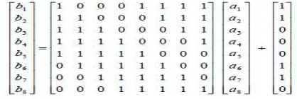
5. S-BOXES OF AES
The S-box has been proven to be the foundation of modern symmetric, such as block and stream ciphers. It is a primary constituent of any block system layout. However, the S-box has several weaknesses, which can make cryptography vulnerable to cryptanalysis. Accordingly, several studies have attempted to enhance security by replacing the fixed S-box with the key-dependent S-box. The S-box of AES is developed by composing a pair of transformations. First, the multiplicative inverse in GF (28) is considered,
with “00” mapping onto itself. Second, an affine transformation is applied [33].
In the present study, 3D Chebyshev is used as a secret key to shuffle the values of the S-box and keep it secret instead of making it public.
6. PROPOSED ALGORITHM
The proposed algorithm, which includes five steps, is discussed in this section.
Step 1: Block transcription
In this step, the image is scrambled by changing the positions of the image pixels. This process is performed by applying block transcription as follows:
1. Decompose the red (R), green (G), and blue (B) components of the image and store them in three N × M arrays, where N and M are the numbers of array rows and columns, respectively.
2. Decompose each component into blocks by dividing N and M by 4. The result represents the number of blocks in each component. For example, if N and M are 512, then the result will be 128 blocks of 4 × 4.
3. Initialize the secret parameters of the 3D logistic map to produce secret keys for the R, G, and B components.
4. Convert the secret keys to the decimal number using Equation 8:
𝑋, = 𝑓𝑙𝑜𝑜𝑟(𝑋, 10 𝑚𝑜𝑑 32). (8)
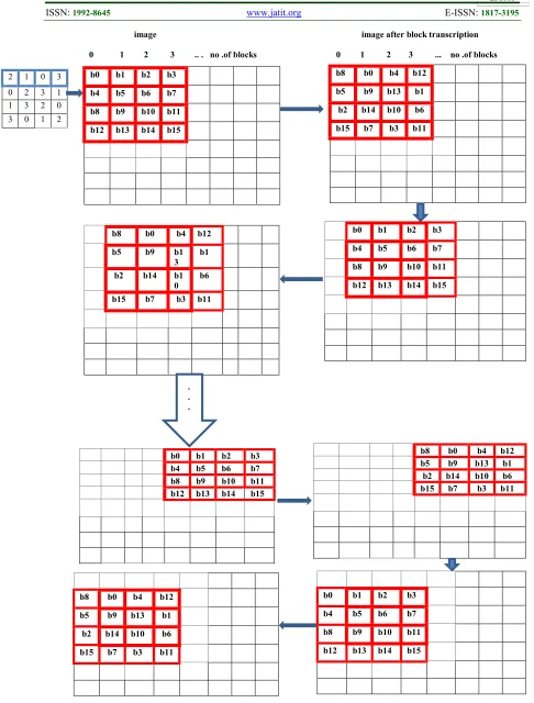
These secret keys, which range from 0 to 31, are stored in a 32 × 32 array. The values in the array should satisfy the condition of not having any repeat value in the row and column, as shown in Figure 3. To simplify, a 6 × 6 array is shown. The values of this array are used as secret keys for block transcription to scramble the image by changing the position of the blocks in the image. Block transcription is inspired by the DNA transcription process. According to this process, the skipped blocks are considered as Introns, while the remaining blocks are considered as Exons. The generation process includes a method
XOR A G C T
A A G C T
G G A T C
C C T A G
[image:6.612.98.211.510.583.2]310 called block transcription, which is based on the mask moving along the image vertically then horizontally, block after block. The value of the key array indicates the number of blocks that should be skipped, while the index of the key array acts as the column sequence of the blocks in the image. In Figure 4, the first value in the key array is 2, which means the first two blocks of the first column of the image will be skipped (as Introns), and the third block (b8) of the first column will be the first block (as the Exon). For simplifying in figure 4 the process of block transcription of a 4 × 4 array is shown instead of 32 × 32 array.
Figure 3array Of Keys
311
image image after block transcription
0 1 2 3 .. . no .of blocks 0 1 2 3 ... no .of blocks
b0 b1 b2 b3
b4 b5 b6 b7
b8 b9 b10 b11
b12 b13 b14 b15
2 1 0 3
0 2 3 1 1 3 2 0 3 0 1 2
b8 b0 b4 b12
b5 b9 b13 b1
b2 b14 b10 b6
b15 b7 b3 b11
b0 b1 b2 b3
b4 b5 b6 b7
b8 b9 b10 b11
b12 b13 b14 b15
b8 b0 b4 b12
b5 b9 b1
3
b1
b2 b14 b1
0
b6
b15 b7 b3 b11
b0 b1 b2 b3
b4 b5 b6 b7
b8 b9 b10 b11
b12 b13 b14 b15
b8 b0 b4 b12
b5 b9 b13 b1
b2 b14 b10 b6
b15 b7 b3 b11
b8 b0 b4 b12
b5 b9 b13 b1
b2 b14 b10 b6
b15 b7 b3 b11
b0 b1 b2 b3
b4 b5 b6 b7
b8 b9 b10 b11
b12 b13 b14 b15
[image:8.612.49.535.67.707.2].
. . .312 The above figure shows that, for the first time, block transcription is applied to the first 4 × 4 blocks in the image and then moves the mask vertically one block to apply block transcription along the image. Subsequently, the mask is moved horizontally (one block down), and block transcription is applied.
Step 2: Apply DNA encoding and implement the reverse or the reverse complement of the DNA as follows:
Generate secret keys from the 3D logistic map and convert them to decimal numbersin the range of 0 to 7 according to Equation 9:
𝑋, = 𝑓𝑙𝑜𝑜𝑟(𝑋, 10 𝑚𝑜𝑑 8) (9)
Convert each pixel in the image to binary and then perform DNA encoding using one of the eight rules in Table 1 as follows:
If the value of the secret key is 0, then rule 1 will be used to encode the pixel; if the value of the secret key is 1, then rule 2 will be used to encode the pixel; and so on until all pixels in the image are encoded.
Generate secret keys from the 3D logistic map and then apply reverse and reverse complement of the DNA on the image pixels as follows:
𝑟𝑒𝑣𝑒𝑟𝑠𝑒 𝑐𝑜𝑚𝑝𝑙𝑒𝑚𝑒𝑛𝑡, 𝑖𝑓 𝑘𝑒𝑦 𝑣𝑎𝑙𝑢𝑒 ≥ 0.5 𝑟𝑒𝑣𝑒𝑟𝑠𝑒, 𝑖𝑓 𝑘𝑒𝑦 𝑣𝑎𝑙𝑢𝑒 < 0.5 .
Step 3: The 3D chaotic map is used to diffuse the relation between the plain and cipher images by modifying the pixel values. This step is performed as follows:
Initialize the three secret parameters of the 3D Chebyshev to produce secret keys for R, G, and B components.
Generate secret keys from the 3D logistic map for R, G, and B components.
Convert them to decimal numbers between 0 and 255 using Equation 10:
𝑋, = 𝑓𝑙𝑜𝑜𝑟(𝑋, 10 𝑚𝑜𝑑 256 ) (10)
Convert them to binary and encode them using one of the eight rules in Table 1.
Exclusive-OR has performed
between the secrets keys, as shown in Table 2.
Exclusive-OR has performed
between the results of the secrets keys and the R, G, and B components of the image, as shown in Table 2.
Step 4: To provide additional security for the encrypted image, a key-dependentS-box of AES based on DNA is proposed. The details of this step are as follows:
1. Convert the value of the AES S-box to binary and then apply DNA encoding using one of the eight rules in Table 1.
2. Divide each sub S-box into four quarters.
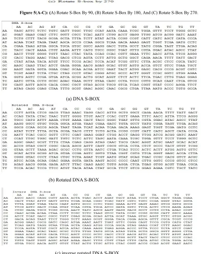
3. Generate secret keys from the 3D Chebyshev in the range of 0 to 3 and convert them to decimal numbers. 4. Rotate each quarter as follows:
0 no rotate
1 rotate quarter by 90° 2 rotate quarter by 180° 3 rotate quarter by 270°
According to these Intron and Exon processes, the quarter with no rotation can be considered an Intron, while the rotated quarter is an Exon. The rotation process is performed as shown in Figure 5 (a)–(c).
313
Figure 5(A-C): (A) Rotate S-Box By 90, (B) Rotate S-Box By 180, And (C) Rotate S-Box By 270.
(a) DNA S-BOX
(b) Rotated DNAS-BOX
(c) inverse rotated DNA S-BOX
[image:10.612.93.506.71.199.2] [image:10.612.87.491.193.704.2]314 6. Substitute each pixel in the image in the
rotated DNA S-box. For example, if the pixel is ATGC, where AT represents the row and GC represents the column, then the intersection of the row with the column will represent the new pixel (GATA).
Step 5: Apply DNA decoding and recombine all components into a single image to obtain the cipher image.
The decryption stages are nearly the same as those of the encrypting stages in reverse order except the substitution will be in the inverse rotated DNA S-box instead of in the rotated DNA S-box.
7. EXPERIMENTAL RESULTS
The experiment is performed using MATLAB R2016aon a PC with Windows 7 OS, Intel Core
i3-3217U processor, 4 GB CPU, and 18.0 GHZ RAM. Different images, such as Pepper, Macaw, Baboon, and Lena, are used as plain images. The following initial values are used with the 3D logistic map and 3D Chebyshev in all the experiments.
1. x0=0.976, y0=0.677, z0=0.973, R=3.80,
β=0.021, α=0.013 for 3D logistic map 2. x0=0.234; y0=-0.398; z0=-0.88 for 3D
Chebyshev map.
Where x for R, y for G, and z for B
Figure 7(a-d) illustrates the plain, scrambled in step1, encrypted images, and corresponding decrypted images respectively.
[image:11.612.125.518.383.703.2]
315 As shown in Figure 7, the decrypted images that used the correct decryption keys are the same plain images from the visual point. Therefore, the proposed algorithm can successfully encrypt and decrypt the images. When the encrypted images are transmitted to the authorized receivers, the correct plain images can be easily decrypted without information loss or distortion.
8. Security Analysis
In this section, several criteria are analyzed to verify the effectiveness and efficiency of the proposed algorithm against different attacks and statistic attack. These criteria include NPCR, UACI,CC, IE, MSE, histogram, and key sensitivity analysis.
8.1 Differential Attack Analysis
Researchers typically use NPCR and UACI as the criteria for examining resistance to differential attacks. NPCR indicates The Number of Pixels Change Rate when one pixel of a plain image is modified. UACI indicates the average intensity of differences between plain and cipher images. A cipher image should significantly differ from its plain image. Such difference can be measured via NPCR and UACI. The proposed cryptosystem can ensure that two cipher images completely differ or that at least one bit of difference exists between them. NPCR and UACI can be derived through the following equations:
𝑁𝑃𝐶𝑅
∑, ( , )×
100%
(11)
Where D(i, j) defined as 𝐷(𝑖, 𝑗) =
0, 𝑖𝑓 𝐶 (𝑖, 𝑗) = 𝐶 (𝑖, 𝑗) 1, 𝑖𝑓 𝐶 (𝑖, 𝑗) ≠ 𝐶 (𝑖, 𝑗)
UACI is defined as follow
𝑈𝐴𝐶𝐼 =
× ∑
( , ) ( , )
× 100%
, (12)
Where W and H denote the width and height of the image, respectively; and c1 and c2 denote the encrypted images before and after one pixel image is change, respectively [22], [36-37]. The test is performed on the proposed algorithm, which involves the modification of a single plain
image pixel. The outcomes of the NPCR and UACI tests are presented in Table 3. The results clearly indicate that a single change in different plain images effectively modifies the encrypted images, thereby proving that the proposed algorithm can effectively resist differential attacks.
8.2 Statistic Attack Analysis
Three criteria have been performed to analysis the proposed algorithm against statistical attacks as shown in the following sections
8.2.1 CC
The efficiency of CC is a critical feature in the new encryption algorithm. This variable is calculated based on the CCs of the cipher and plain pixels. A good encryption algorithm can decrease the correlation between adjacent pixels. To analyze the CC of the cipher image, Equation 13 is used as follows:
𝐴̅ = ∑ 𝑥
𝐵 = ∑ 𝑦
r=
∑ ( ̅)( )∑ ( ̅) (( ) )
(13)
where N is the number of selected adjacent pixels that will be used to calculate the CC of an image; and xi and yi are the values of adjacent pixels vertically, horizontally, diagonally, and
anti-diagonally in the plain and cipher images[1],[3],[38].
316
[image:13.612.83.547.115.189.2]Table3. NPCR And UACI Of The Different Images.
[image:13.612.81.545.215.279.2]Table 4. CC (Horizontal, Vertical, Diagonal, And Anti-Diagonal) Of The Different Plain Images.
Table 5. CC (Horizontal, Vertical, Diagonal, And Anti-Diagonal) Of The Different Cipher Image
8.2.2 IE
IE is an essential randomness feature that is applied to various fields, such as lossless data compression, statistical inference, machine learning, and cryptography. This criterion can measure the distribution of gray values in an image. When IE is high, the distribution of gray values is uniform. The definition of IE is expressed as Equation 14:
H(𝑚) = ∑ 𝑃(𝑚𝑖) 𝑙𝑜𝑔 𝑃(𝑚𝑖) (14)
[image:13.612.85.552.305.371.2]where mi is the ith gray value for the L level gray image, and P(mi) is the appearance probability of mi. The IE of an ideal random image is 8[1-2],[5]. The IE outcomes of the different plain and cipher images used in this study are presented in Table 6. As shown in the table, the entropy in the encrypted images is nearly 8.
Table 6. The Result IE Of The Different Plain And Cipher Images.
Images Entropy/plain
image Entropy/cipher image
Pepper 7.7798 7.9990
Macaw 7.6253 7.9989
Baboon 7.7681 7.9992
Linea 7.677 7.9997
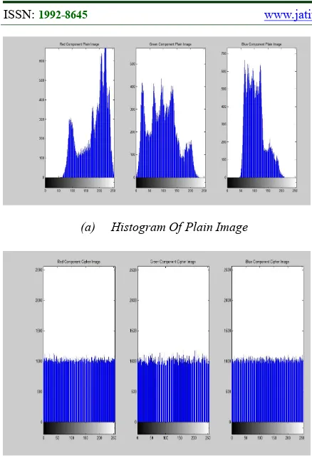
8.2.3 Histogram
A histogram is used to present the distribution of pixels in an image. To resist statistical attacks, the histogram of a cipher image should be sufficiently uniform. If the histogram of a cipher image is uniform then the encryption scheme will be faced the statistical attacks. Otherwise, attackers may get important information from the plain image by investigating the histogram of the cipher image [2-3],[5].
The histograms of the plain and cipher images for the R, G, and B components are presented in Figure 8 (a) and 8 (b), respectively. The histogram of the encrypted image is flat and completely differs from that of the plain image. Similar to the plain image, the encrypted image exhibits no redundancy. Therefore, it can resist statistical attacks.
Images NPCR UACI
R G B R G B
Pepper 99.5060 99.5445 99.5018 30.5800 32.8549 33.5133
Macaw 99.5060 99.5033 99.5075 29.6229 32.8923 33.3911
Baboon 99.5026 99.5300 99.5235 34.4848 31.8003 32.3615
Linea 99.5148 99.5224 99.5018 32.6698 29.8269 31.5435
Direction Horizontal Vertical Diagonal Anti-Diagonal
Images R G B R G B R G B R G B
Pepper 0.9877 0.9936 0.9869 0.9879 .9949 0.9881 0.9753 0.9881 0.9748 0.9777 0.9897 0.9771 Macaw 0.9812 0.9772 0.9775 0.9891 0.9860 0.9867 0.9783 0.9728 0.9732 0.9724 0.9670 0.9675 Baboon 0.9896 0.9896 0.9824 0.9835 0.9842 0.9721 0.9738 0.9746 0.9553 0.9764 0.9770 0.9601 Linea 0.9865 0.9871 0.9749 0.9931 0.9936 0.9862 0.9772 0.9786 0.9581 0.9840 0.9844 0.9681
Direction Horizontal Vertical Diagonal Anti-Diagonal
Images R G B R G B R G B R G B
[image:13.612.90.296.648.726.2]317
(a) Histogram Of Plain Image
(B) Histogram Of Cipher Image
Figure 8 (A-B): (A) Histogram Of Plain Image, (B) Histogram Of Cipher Image.
8.3 MSE
MSE denotes the difference between the plain and cipher images. This difference must be extremely high to achieve good performance. MSE is calculated for the cipher image using Equation 15 as follows:
[image:14.612.88.307.68.395.2]MSE= ∑ ∑ 𝑥(𝑖, 𝑗) − 𝑦(𝑖, 𝑗) (15) where x (i, j) represents the plain image, y (i, j) represents the cipher image, and i and j are the pixel positions of the M × N image. MSE is zero when x (i, j) = y (i, j) [5],[29],[39]. Table 7 illustrates the result of MSE for the different cipher images.
Table 7. Result Of MSE For The Different Cipher Images.
Images MSE
R G B
Pepper 96.271 96.851 97.292
Macaw 94.987 97.935e 93.380
Baboon 94.116 98.344 99.305
Linea 98.383e 94.32 95.051
8.4 Key Sensitivity Analysis
Chaotic maps are extremely sensitive to the initial condition and the system control parameters. If a small change occurs, then the decrypted image will no longer be similar to the plain image. Key sensitivity has two approaches. First, when a tiny altered key is approved to encrypt the same image and a entirely altered cipher image is acquired, the CC among the cipher images should be extremely small. Second, the cipher image cannot be correctly decrypted although only a tiny altered exists between the encryption and decryption keys [1-2], [5], [2[1-2], [24], [40-41].
The plain image is encrypted into a pair of different keys for the first approach. Suppose that the selected keys are (α = 0.013, β = 0.021, and R = 3.80), whereas the slightly different keys are (α = 0.013000001, β = 0.021, and R = 3.80), (α = 0.013, β = 0.021000001, and R = 3.80), and (α = 0.013, β = 0.021, and R = 3.80000001), the results of the CC among the cipher images are presented in Table 8.
Table 8. Result Of CC For The Different Keys
Keys CC
Red Green Blue
α=0.013000001 -0.0439 -0.0448 -0.0437
β=0.021000001 -0.0504 -0.0501 -0.0483
R=3.80000001 -0.0433 -0.0449 -0.0445
.
As shown in the table, CCis nearly zero when a slight change occurs in the keys. For the second approach, the plain image is initially encrypted with the selected α = 0.013, β = 0.021, and R = 3.80, whereas the slightly different keys (α=0.013000001, β=0.021, R=3.80), (α=0.017,
β=0.021000001, and R=3.80), and (α=0.017,
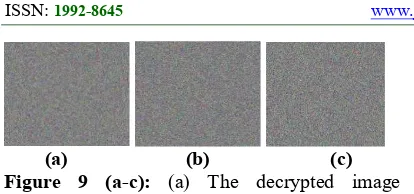
[image:14.612.85.293.633.722.2]318
(a) (b) (c) Figure 9 (a-c): (a) The decrypted image following there is a small alteration in value R, (b) the decrypted image following is a small alteration in value β, (c) the decrypted image following a small alteration in value R.
8.5 Comparison With Other Methods
[image:15.612.88.295.73.170.2]In this section, statistical performance is compared with others image encryption algorithms [42-46] in the statistical analysis (IE, CC (Vertical, Horizontal and diagonal), NPCR and UCAI) by using Lena image, which are shown in Table 8 where the best result in the table is illustrated by a bold font.
Table 8. Comparison With Others Algorithms
From the above table, it can show the IE value of the four algorithms are all very near to 8, which can promise no information leak of cipher image. All values of correlation coefficient of the four algorithms in horizontal, vertical and diagonal direction extremely close 0. Compare to the Refs. [42-46], the UACI and NPCR values of proposed algorithm is more close to the ideal value 37.2355 and 99.8666 % respectively .The proposed algorithm in Ref. [42] are constructed by DNA sequences and genetic algorithm, and has quite complex structure, which may lead to side effect for the performance. In contrast, our scheme takes advantage of the 3D chaotic map and Key-dependent DNA S-Box of AES to achieve high complexity with simple structure. So proposed algorithm of image encryption shows some advantage and can be regarded as a candidate for image encryption in practical application.
9. CONCLUSION AND FUTURE WORKS
This study proposes the use of a 3D chaotic system, DNA sequence, and the key-dependent DNA S-box of AES to encrypt and decrypt color
images. The proposed algorithm includes five steps: block transcription, encoding of DNA base, reverse/reverse complement of DNA, use of a 3D chaotic map, and key-dependent DNA S-box of AES. Block transcription is used to scramble image pixels by changing their locations in the image. The encoding of DNA base, reverse/reverse complement of DNA are conducted to change the pixel values for diffusing image pixels. A 3D chaotic map is adopted to generate a secret key for shuffling or diffusing the pixels in an image. The S-box of AES is scrambled using secret keys by changing the coordinate values of the DNA S-box of AES to keep it a secret. Then, the image is substituted into the DNA S-box of AES. These steps aim to shuffle and diffuse the image more than once to ensure high security. The experimental results indicate that the proposed algorithm can provide high levels of security and resistance against many types of attacks. In a future research, the additional properties of DNA and how they can be linked to the encryption of images will be investigated.
References IE CC NPCR UCI
Horizont
al Vertical Diagonal
Ref.42 7.9992 0.0058 0.0022 0.0031 99.71% 33.63%
Ref.43 7.9975 0.0009 0.0038 −0.0002 99.6653 0.334758
Ref.44 7.9993 0.0020 0.0009 0.0016 99.647 0.334815
Ref.45 7.9994 0.0009 −0.0022 0.0149 99.6427 0.335615
Ref.46 7.9978 −0.0054 0.0093 −0.0009 97.1394 0.331084
[image:15.612.91.522.244.364.2]319
REFERENCES
[1] Zhang, Q.; Xue, X.; Wei, X., A novel image encryption algorithm based on DNA subsequence operation. The Scientific World Journal 2012, 2012.
[2] Song, C.; Qiao, Y., A novel image encryption algorithm based on DNA encoding and spatiotemporal chaos. entropy 2015, 17
(10), 6954-6968.
[3] Niyat, A. Y.; Hei, R. M. H.; Jahan, M. V., A RGB image encryption algorithm based on DNA sequence operation and hyper-chaotic system.
[4] Zhang, L.; Gao, T.; Yang, R. In DNA coding and central dogma based image encryption using vigenere cipher and chaos map, Intelligent Control and Information
Processing (ICICIP), 2014 Fifth
International Conference on, IEEE: 2014; pp 80-85.
[5] Chai, X.; Gan, Z.; Yuan, K.; Chen, Y.; Liu, X., A novel image encryption scheme based on DNA sequence operations and chaotic
systems. Neural Computing and
Applications 2017, 1-19.
[6] Adams, C.; Tavares, S., The structured design of cryptographically good S-boxes. journal of Cryptology 1990, 3 (1), 27-41.
[7] Mar, P. P.; Latt, K. M., New analysis methods on strict avalanche criterion of S-boxes. World Academy of Science, Engineering and Technology 2008, 48 (150-154), 25.
[8] Hussain, I.; Shah, T.; Afzal, M.; Mahmood, H., Comparative analysis of S-boxes based on graphical SAC. Analysis 2010, 2 (5). [9] Krishnamurthy, G.; Ramaswamy, V.,
Making AES stronger: AES with key dependent S-box. IJCSNS International Journal of Computer Science and Network Security 2008, 8 (9), 388-398.
[10] Janadi, A.; Tarah, D. A. In AES immunity Enhancement against algebraic attacks by using dynamic S-Boxes, Information and
Communication Technologies: From
Theory to Applications, 2008. ICTTA 2008. 3rd International Conference on, IEEE: 2008; pp 1-6
[11] El-Sheikh, H. M.; El-Mohsen, O. A.; Elgarf, S. T.; Zekry, A., A new approach for designing key-dependent S-box defined over GF (24) in AES. International Journal of Computer Theory and Engineering 2012, 4 (2), 158.
[12] Paul, S.; Dasgupta, P.; Naskar, P.K.; Chaudhuri, A., Secured image encryption scheme based on DNA encoding and chaotic map. International Information
and Engigneering Technology
Assocation, 2017,1, 0–75.
[13] Al-Mashhadi, H. M.; Abduljaleel, I. Q. In Color image encryption using chaotic maps, triangular scrambling, with DNA sequences, Current Research in Computer Science and Information Technology (ICCIT), 2017 International Conference on, IEEE: 2017; pp 93-98.
[14] Niu, Y.; Zhang, X.; Han, F., Image
Encryption Algorithm Based on
Hyperchaotic Maps and Nucleotide
Sequences Database. Computational
intelligence and neuroscience 2017, 2017. [15] Enayatifar, R.; Abdullah, A. H.; Isnin, I. F.; Altameem, A.; Lee, M., Image encryption using a synchronous permutation-diffusion
technique. Optics and Lasers in
Engineering 2017, 90, 146-154.
[16] Mokhtar, M. A.; Gobran, S. N.; El-Badawy, E.-S. A. In Colored Image Encryption Algorithm Using DNA Code and Chaos Theory, Computer and Communication Engineering (ICCCE), 2014 International Conference on, IEEE: 2014; pp 12-15. [17] Jain, A.; Agarwal, P.; Jain, R.; Singh, V.,
Chaotic Image Encryption Technique using S-box based on DNA Approach.
International Journal of Computer
Applications 2014, 92 (13).
[18] Zhang, Q.; Liu, L., DNA coding and chaos-based image encryption algorithm. Journal
of Computational and Theoretical
Nanoscience 2013, 10 (2), 341-346. [19] Jacob, G.; Murugan, A., An Encryption
Scheme with DNA Technology and JPEG Zigzag Coding for Secure Transmission of Images. arXiv preprint arXiv:1305.1270 2013
[20] Zhang, Q.; Guo, L.; Xue, X.; Wei, X. In An image encryption algorithm based on DNA sequence addition operation, Bio-Inspired Computing, 2009. BIC-TA'09. Fourth International Conference on, Ieee: 2009; pp 1-5.
320 [22] Singh, K.; Kaur, K., Image encryption using
chaotic maps and DNA addition operation and noise effects on it. International Journal of Computer Applications (0975–8887) Volume 2011.
[23] Khade, P. N.; Narnaware, M., 3D chaotic functions for image encryption. IJCSI International Journal of Computer Science Issues 2012, 9 (3), 323-328.
[24] Tong, X.-J.; Zhang, M.; Wang, Z.; Liu, Y., A image encryption scheme based on dynamical perturbation and linear feedback shift register. Nonlinear Dynamics 2014, 78 (3), 2277-2291.
[25] Thampi, C.; Jose, D., More Secure Color Image Encryption Scheme Based on 3D Chaotic Maps. International Journal For Advance Research In Engineering And Technology 2015, 1
[26] Alabaichi, A. M., Color Image Encryption using 3D Chaotic Map with AES key Dependent S-Box. International Journal of Computer Science and Network Security (IJCSNS) 2016, 16 (10), 105.
[27] Lv, Z.; Zhang, L.; Guo, J. In A Symmetric Image Encryption Scheme Based on Composite Chaotic Dispersed Dynamics System, IEEE Proceedings of the Second International Symposium on Computer Science and Computational Technology (ISCSCT’09), 2009; pp 191-194.
[28] Kocarev, L.; Tasev, Z. In Public-key encryption based on Chebyshev maps, Circuits and Systems, 2003. ISCAS'03. Proceedings of the 2003 International Symposium on, IEEE: 2003; pp III-III. [29] Shyam, M.; Kiran, N.; Maheswaran, V., A
novel encryption scheme based on DNA computing. HIPC2007 2007.
[30] Mandge, T.; Choudhary, V. In A DNA encryption technique based on matrix manipulation and secure key generation scheme, Information Communication and Embedded Systems (ICICES), 2013 International Conference on, IEEE: 2013; pp 47-52.
[31] 1. Nath, A.; Roy, D.; Nag, R., Image
Encryption using DNA Encoding
Techniques: a brief overview. International Journal 2016, 4 (10).
[32] Al-Wattar, A. H.; Mahmod, R.; Zukarnain, Z. A.; Udzir, N. I., A New DNA-Based Approach of Generating Key-dependent ShiftRows Transformation. arXiv preprint arXiv:1502.03544 2015.
[33] Gupta, L.; Gupta, R.; Sharma, M., Low Complexity Efficient Image Encryption Technique Based on Chaotic Map. International Journal of Information & Computation Technology 2014, 4 (11), 1029-1034.
[34] Al-Wattar, A. H. S.; Mahmod, R.; Zukarnain, Z. A.; Udzir, N. I., Generating a new S-Box inspired by biological DNA. International Journal of Computer Science and Application 2015
[35] Al-Wattar, A. H.; Mahmod, R.; Zukarnain, Z. A.; Udzir, N., A NEW DNA BASED APPROACH OF GENERATING KEY-DEPENDENTMIXCOLUMNS
TRANSFORMATION. International
Journal of Computer Networks & Communications 2015, 7 (2), 93.
[36] Wei, X.; Guo, L.; Zhang, Q.; Zhang, J.; Lian, S., A novel color image encryption algorithm based on DNA sequence operation and hyper-chaotic system. Journal of Systems and Software 2012, 85 (2), 290-299.
[37] Liu, H.; Wang, X., Image encryption using DNA complementary rule and chaotic maps. Applied Soft Computing 2012, 12 (5), 1457-1466.
[38] Babaei, M., A novel text and image encryption method based on chaos theory and DNA computing. Natural computing 2013, 12 (1), 101-107.
[39] Srivastava, R.; Singh, O., Performance Analysis of Image Encryption Using Block Based Technique. International Journal of Advanced Research in Electrical, Electronics and Instrumentation Engineering 2015, 4 (5), 4266-4271. [40] Chen, J.-x.; Zhu, Z.-l.; Yu, H., A fast
chaos-based symmetric image cryptosystem with an improved diffusion scheme.
Optik-International Journal for Light and Electron Optics 2014, 125 (11), 2472-2478.
[41] Jawad, L. M.; Sulong, G., Chaotic map-embedded Blowfish algorithm for security enhancement of colour image encryption. Nonlinear Dynamics 2015,
81 (4), 2079-2093.
[42] Enayatifar, R.; Abdullah, A. H.; Isnin, I. F., Chaos-based image encryption using a hybrid genetic algorithm and a DNA
sequence. Optics and Lasers in
321 [43] Zhang, G.; Liu, Q., A novel image
encryption method based on total
shuffling scheme. Optics
Communications 2011, 284 (12), 2775-2780.
[44] Zhu, Z.-l.; Zhang, W.; Wong, K.-w.; Yu, H., A chaos-based symmetric image encryption scheme using a bit-level permutation. Information Sciences
2011, 181 (6), 1171-1186.
[45] Wang, Y.; Wong, K.-W.; Liao, X.; Chen, G., A new chaos-based fast image encryption algorithm. Applied soft computing 2011, 11 (1), 514-522 [46] Abdullah, A. H.; Enayatifar, R.; Lee, M., A
hybrid genetic algorithm and chaotic function model for image encryption.