Secure Data Collection in Constrained Tree-Based Smart Grid Environments
Haiming Jin
1, Suleyman Uludag
2, King-Shan Lui
3, and Klara Nahrstedt
11
Department of Computer Science, University of Illinois at Urbana-Champaign, IL, USA
2Department of Computer Science, University of Michigan - Flint, MI, USA
3
Department of Electrical and Electronic Engineering, The University of Hong Kong, Hong Kong
Abstract—To facilitate more efficient control, massive amounts of sensors or measurement devices will be deployed in the Smart Grid. Data collection then becomes non-trivial. In this paper, we study the scenario where a data collector is responsible for collecting data from multiple measurement devices, but only some of them can communicate with the data collector directly. Others have to rely on other devices to relay the data. We first develop a communication protocol so that the data reported by each device is protected again honest-but-curious data collector and devices. To reduce the time to collect data from all devices within a certain security level, we formulate our approach as an integer linear programming problem. As the problem is NP-hard, obtaining the optimal solution in a large network is not very feasible. We thus develop an approximation algorithm to solve the problem. We test the performance of our algorithm using real topologies. The results show that our algorithm successfully identifies good solutions within reasonable amount of time.
I. INTRODUCTION
One of the significant hallmarks of the Smart Grid (SG) initiative is the pervasive data sensing to facilitate a more efficient control. While the existing Supervisory Control And Data Acquisition (SCADA) system already collects data from various sensors, the scale and scope of the data collection in the SG are expected to pose new challenges. Applications of data sensing in the SG include conditional and structural monitoring of Distributed Energy Resources and renewables in the generation; State-of-Charge monitoring; substation, trans-former, underground and overhead lines in the transmission and distribution; and collection of information from smart meters in the Advanced Metering Infrastructure (AMI) [1].
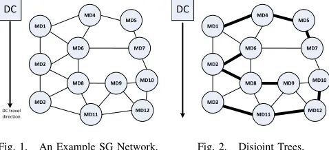
In addition to the emerging and new sensing in the SG, data collection from the legacy telemetric devices widely deployed in the field needs to be accommodated as part of the infrastruc-ture, at the very least, in the transitional period. An example of such legacy telemetric collection need is provided in [2]. In this scenario, a mobile data collector (DC) moves along a road, or a certain path, to collect data from measurement devices (MDs). It can only connect directly to the MDs that are within DC’s proximity. We call the MDs that can talk to
the DC directly root MDs. Those MDs that are outside the
communication range of the DC have to send data to the DC through root MDs in a multihop manner. Figure 1 presents a simple example where only root MDs (MD1, MD2, MD3) can talk to the DC directly. Other remote MDs should send their data to one of the root MDs. Note that the underlying data collection paradigm of the aforementioned case is present in many other emerging sensing and measurement scenarios [1], [3], especially when sequential data collection is needed over
DC
MD1
MD4
MD6
MD2
MD3 MD8
MD11 MD5
MD10 MD7
MD9
MD12
[image:1.612.318.557.175.284.2]DC travel direction
Fig. 1. An Example SG Network.
DC
MD1
MD4
MD6
MD2
MD3 MD8
MD11 MD5
MD10 MD7
MD9
MD12
Fig. 2. Disjoint Trees.
a multihop communications topology. To reduce the number of messages needed for the whole data collection, we propose generating several disjoint trees, each rooted at a certain MD, such that the trees reach all MDs. Fig. 2 shows an example, where bold edges show the trees formed from the roots.
In this paper, we are interested in secure, scalable, and optimized data collection in the SG. Our objective is to reduce the total data collection time while ensuring the confidentiality of the data. We encrypt data in a way that while allowing the relaying MDs to verify the message integrity, they cannot
read the content under thehonest-but-curiousmodel. The data
collection time is reduced through identifying data collection trees that have minimum sum of depths. We develop an optimization problem for the secure data collection, which is NP-Hard, and then develop an approximation algorithm.
The rest is organized as follows: Sec. II presents the related work. Tree-based secure data collection is detailed in Sec. III. Sec. IV develops the optimization problem and solution together with an approximation algorithm. Simulation results are given in Sec. V. Sec. VI concludes the paper.
II. RELATEDWORK
To the best of our knowledge, confidential data collection with integrity validation by means of forming disjoint trees to minimize the total collection time has not been studied in the literature. We dissect our problem into three constituents in order to present a discussion of the partially related work: (1) Multi-sink data collection in Wireless Sensor Networks (WSNs) and opportunistic networks [4], (2) Tree or cluster formation, and (3) Secure data collection.
Station Problem from [7] where the problem of positioning data collecting nodes in a WSN is studied as a maximum flow problem with the objective of finding the optimal data rate. The NP-completeness proof of the problem is also
given in [7]. While retaining the complexity1, our problem
is about the minimization of total time of the data collection and incorporates the security aspect. The tree formation of our approach connotes clustering algorithms, especially in WSNs [9]. However, unlike the goals of WSN clustering on node reachability and network longevity, we focus on security and data collection time minimization.
Finally, as for the security of the data collection task, there are two major approaches: One is to ensure the protection of the data content directly without regard to the data seman-tics. An approach presented in [10] is based on symmetric cryptography to provide data confidentiality and authentica-tion between sensors and the base staauthentica-tion. [11] describes a protocol for DC to collect data from an MD, but direct communication between DC and MD is assumed. Another category for providing security exploits the aggregate statistics of the sensed data, such as summation, average, minimum, maximum, etc. These approaches take advantage of in-network
data processing (also referred to as aggregation) to induce
some obfuscating operations on the transmitted data [12]– [20]. Our problem formulation does not assume any statistical property for in-network processing.
III. SECUREDATACOLLECTIONVIATREES
A. Overview
A Power Operator (PO) delegates a DC to collect data from a certain number of MDs. We assume each entity in the system possesses a pair of public and private key as long-term secrets. We denote the public key and private key of node
A as A+ and A−, respectively. Before an MD is installed in
the field, it is configured with its own public/private key pair and the public key of PO, but not the public key of DC. Our architecture does not require an MD to know the public keys of its neighbors, either. Apart from the keys, all entities are
also configured with Diffie-Hellman (DH) parametersgand p
for shared key establishment2. PO, DC, and MDs all agree to
use the following basic cryptographic functions.
1) PKE(K,M) : Public key encryption on message M using
keyK
2) SKE(K,M): Symmetric key encryption onM usingK
3) SIG(A,M): Signature of M byA (created usingA−)
4) HASH(K,M): Compute the keyed-hash ofM using keyK
The security objective of the data collection is to protect the data reported by each MD such that only the PO can read the data generated by MDs. That is, even though the data reported has to be relayed by other MDs and the DC, these MDs and
1Complexity of the optimization part of our problem may also be obtained
from the classicalmulti-facility location problem[8].
2pis a prime number, andgis a primitive rootmod p. Let A pick a secret
aand B pick a secretb. A sendsgamod pto B, and B sendsgbmod pto A. A can then compute the shared key by(gbmod p)amod p.Bcomputes the key by(gamod p)bmod p.
DC should not be able to read it. To achieve this efficiently, data should be encrypted by a shared key between a certain MD and the PO using symmetric key cryptography. We adopt the DH mechanism to develop the shared keys. On the other hand, to allow intermediate MDs to perform integrity checks,
all the MDs within the same disjoint tree share aGroup Key
GK (to be explained below) with PO and DC.
We now briefly describe the whole procedure of data collection. First, the PO determines the disjoint trees to be used for data collection. Then, it provides the tree information and the necessary key information to the DC. The DC then talks to each root MD along its path to collect data. Root MD sends the key information along each branch on its tree to collect data. After it receives data from all MDs in its tree, it sends the data to DC.
B. Data Collection on a Branch
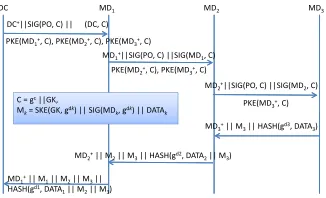
We first describe a simple situation that data is collected along a certain branch on the tree. We then describe the data collection of a whole tree. Fig. 3 presents how DC collects data
on a tree branch spanning fromMD1, the root MD, to MD2,
DC MD1 MD2 MD3
C = gc||GK,
Mk= SKE(GK, gd k) || SIG(MD
k, gd k) || DATA
k
PKE(MD1+, C), PKE(MD2+, C), PKE(MD3+, C)
DC+||SIG(PO, C) || (DC, C)
PKE(MD2+, C), PKE(MD3+, C)
PKE(MD3+, C)
MD1+||SIG(PO, C) ||SIG(MD1, C)
MD2+||SIG(PO, C) ||SIG(MD2, C)
MD3+|| M3|| HASH(gd3, DATA3)
MD2+|| M2|| M3|| HASH(gd2, DATA2|| M3)
MD1+|| M1|| M2|| M3||
[image:2.612.357.520.319.418.2]HASH(gd1, DATA 1|| M2|| M3)
Fig. 3. Data Collection on a Tree Branch.
and then MD3. Let the branch be MD1→MD2→. . .MDl,
whereMD1 is the root MD. The public DH key of PO isgc
(mod pis dropped for brevity), and the group key isGK. The
key information created by the PO is denoted byC=gc||GK,
where||represents the concatenation operation. Each MD on
the branch must receiveC to develop a shared key with the
PO. The detailed procedure of data collection is as follows:
1) DC→MD1:DC+||SIG(PO,C)||SIG(DC,C)||
[PKE(MD+k,C),1≤k≤l]
To protect C from eavesdroppers, C is encrypted using the
public keys of the MDs. As only the PO knows the public
keys of all the MDs, PKE(MD+k,C) for 1 ≤k ≤l are
created by PO and sent to DC, which will be discussed in
Section III-C.MD1authenticatesCby verifying the signature
SIG(PO,C).MD1 verifies the legitimacy of DC by verifying
SIG(DC,C).MD1then signsCusing its public key and sends
the signature together with other information to the next MD along the branch.
2) MD1→MD2:MD+1||SIG(PO,C)||SIG(MD1,C)||
[PKE(MD+k,C),2≤k≤l]
Note that as MD1 also sends MD+1 to MD2 so that MD2
does not need to know any public key of any MD before the
similar operations asMD1that it authenticatesCandMD1. It
then passes the key information to the next MD (more details will be provided in Section III-C).
3) MDi→MDi+1: MD+i ||SIG(PO,C)||SIG(MDi+1,C)||
[PKE(MD+k,C),i+1≤k≤l]
Intermediate MDs on a tree branch keep forwarding the key
information to the next MD after retrievingGK andgc from
C.
4) MDl−1→MDl:MD+l−1||SIG(PO,C)||SIG(MDl−1,C)||
PKE(MD+l ,C)
MDl is the last MD on the branch. After verifying C, it
prepares the reported data. It first generates its own DH
half key gdl and develops the shared key between itself and
the PO, which is gcdl. Let DATA
l be the data encrypted
and integrity protected using gcdl. MD
l then sends DATAl
to MDl−1 for relaying to DC and finally to PO. To allow
MDl−1 to perform authentication check on DATAl, MDl
computes the hash of DATAl using gdl. MDl should also
let MDl−1 and the PO knows what gdl is. Let message
Mk = SKE(GK,gdk)||SIG(MDk,gdk)||DATAk for 1≤k≤l.
Ml contains the DH half key and the encrypted data to be
delivered to the PO.
5) MDl→MDl−1:MD+l ||Ml||HASH(gdl,DATAl)
MDl−1 first retrieves gdl from SKE(GK,gdl) contained in
Ml and verifies SIG(MDl,gdl). It then can authenticate the
message by verifying the hash. Note that although MDl−1
knowsgcandgdl, according to the property of DH protocol,
MDl−1 still cannot compute gcdl to decrypt DATAl. Thus,
DATAl remains secret toMDk for allk=1, . . . ,l−1 and the
DC. After verifying the message, MDl−1 prepares its own
encrypted dataDATAl−1and sends bothDATAl andDATAl−1
toMDl−2 together with the required key information.
6) MDl−1→MDl−2:
MD+l−1||Ml−1||Ml||HASH(gdl−1,DATAl−1||Ml)
MDl−2processes the message in a similar manner asMDl−1
does. Finally, MD1would receive a message fromMD2 that
contains all the data fromMD2toMDl. It can then prepare a
message that contains all the data on the branch for the DC.
7) MD1→DC:
MD+1||M1||M2||. . .||Ml||HASH(gd1,DATA1||M2||. . .||Ml)
C. Tree Structure Representation
To facilitate a root MD to collect data for its tree, it has to know which neighbors belong to its tree. The root MD also
needs to inform its children oftheir children. In other words,
the tree structure has to be embedded in the message from the DC to the root MD, and passed along to the MDs on the tree.
C=gc||GKhas to be encrypted using the public key of each
MD on the tree. We use PKE(MD+i ,C) for all MDi on the
tree to represent the tree. Let E(i) =PKE(MDi,C), and let
T(i)be the tree representation rooted at MDi. We further let
MDch1, . . . ,MDchm be the children ofMDi if it is not a leaf.
The representation is as follows:
T(i) =
(
[E(i),T(ch1), . . . ,T(chm)] ifMDi is not a leaf
E(i) ifMDi is a leaf
Refer to the tree rooted at MD2 in Fig. 2, T(2) =
[E(2),E(6),[E(8),E(9)]].
When MDi receives T(i), it can retrieve C from
E(i). It can also identify its children to forward key
information. Let MDj be a child of MDi, it sends
MD+i ||SIG(PO,C)||SIG(MDi,C)||T(j)toMDj.
An MD should wait for all its children to report data before sending its data to its parent. Data report-ing does not have to follow the tree structure. A
par-ent MD can simply append all Mk of descendant MDk
together. For example, MD2 in Fig. 2 can send DC
MD+2||M2||M6||M8||M9||HASH(gd2,DATA2||M6||M8||M9).
D. Completing the Protocol
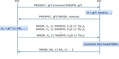
We now complete the protocol by describing the communi-cation between the PO and the DC. Fig. 4 illustrates the infor-mation exchange. They first use the DH protocol to establish
PO DC
PKE(DC+, ga||nonce) SIG(PO, ga)
PKE(PO+, gb) SKE(K, nonce)
K = gabmod p
SKE(K, C1|| SIG(PO, C1)) || T(r1),
SKE(K, C2|| SIG(PO, C2)) || T(r2),
:
SKE(K, Ck|| SIG(PO, Ck)) || T(rk)
Ck= gck|| GKk
SKE(K, M1|| M2|| … )
[image:3.612.338.536.270.369.2]Contact the head MDs
Fig. 4. Communication between PO and DC.
a shared secret K to secure the subsequent conversation. PO
picks the group keys to be used. The tree structure and the
key information are then encrypted using K. Suppose there
are kroot MDs,MDr1,MDr2, . . . ,MDrk. PO can use different
DH half keys and group keys to develop shared keys with the MDs on different trees. Let the DH half key and the group
key for the tree rooted atMDhi be g
ci andGK
i, respectively.
We further let Ci=gci||GKi. For root MD MDhi, PO sends
SKE(K,Ci||SIG(PO,Ci))||T(hi) to DC. DC can then verify
the signature for eachCi and talk to the root MDs to collect
data as described earlier. After all data are collected, DC
encrypts Mj for each MDj it collects using K. Note that
Mj=SKE(GKi,gdj)||SIG(MDj,gdj)||DATAj, which belongs
to the tree ofMDi, contains enough information for the PO to
retrieve and verify the data.
E. Security Discussion and Its Complexity
In our protocol, the confidentiality of the data is ensured through the Diffie-Hellman keys. The DH half keys are trans-mitted under encryption. Eavesdroppers cannot read them. The
data remains confidential to the honest-but-curious DC and
the data in a hop-by-hop manner, tampering can be identified early so that network resources would not have been spent on transmitting the tampered data from the leaf to the PO. Our protocol is thus secure from both active and passive attacks when the keys are not leaked. (We consider the risk of leaking the group key in our problem formulation in Sec. IV-A).
We now study the computational complexity of an MD. We only consider public key and DH operations since symmetric key and hash operations are not expensive. The leaf MD receives one message from its parent and sends one message to its parent in each data collection cycle. It has to decrypt the key information and verify two signatures for the message received. To prepare the reply, it generates a DH half key and signs it. Five operations are needed in total for a leaf node. Similar operations are needed for the messages to and from the parent for each non-leaf MD. To send messages to its children, an MD has to sign the key information. For each reply from a child, it has to verify the signature of the half key provided by the child. Therefore, the total number of operations a non-leaf MD needs to perform is 6 + number of children.
IV. COLLECTIONTREEFORMATION
A. Problem Description
In this section, we describe how PO constructs the disjoint
data collection trees on the network connectivity graph G of
MDs. Since the PO has complete information of the topology,
graphG, a connected vertex set of all MDs, is knowna priori.
We use set M={1,2,· · · } to denote the index set of these
MDs. Furthermore, if there is a direct connectivity between two MDs then an undirected edge exists between them in
graph G. Furthermore, we define the set of all MDs that can
potentially be selected as therootMDscandidate set, and we
useRto denote the set of indices of these candidate root MDs.
The largest possible candidate set consists of all the MDs that can be physically within the communication range of the DC when it is traveling along the predefined data collection path.
For example, in Fig. 1, R={1,2,3}.
Our objective is to minimize the sum of the data collection time over all trees. We further assume identical link delays. Then, we can use the depth of a data collection tree to represent the time needed to collect data from this particular tree and the summation of the depths over all constructed trees to represent the overall data collection time.
Apart from the time to collect data, we also consider the security level of the group key. As the MDs may not be in a very secure physical environment, there is a risk of leaking the group key. If the group key is stolen, the attacker can decrypt
SKE(GK,gdk)inM
k to obtaingdk and create the correct hash
of fake data. Although the PO can finally detect the data were not legitimate, network resource will be wasted in transmitting
the message. Assume that everyMDi(i∈ M)leaks the group
key with probability pi. Then the probability that the group
key of a treeT is leaked is Pleak(T) =1−∏i:MDi∈T(1−pi).
To ensure the security level of every constructed tree T, we
limitPleak(T)to be no larger than some predefined threshold.
We assume identical pi’s. Then, if we limit the group key
leaking probability to be no larger than some threshold value
Pthreshold, we have:
Pleak(T) =1−
∏
i:MDi∈T(1−pi) =1−(1−p)|
T|≤P
threshold
In other words, the cardinality of every constructed tree should satisfy
|T | ≤log(1−Pthreshold)
log(1−p) =Nthreshold (1)
As detailed in the next subsection, we formulate the
opti-mization problem with a Min−Sum−Max objective to
mini-mize the summation of the depths over all constructed trees with the aforementioned security constraint.
B. Mathematical Formulation
We state the optimal collection tree formation (CTF)
prob-lem into a binary integer programming formulation as follows:
min
∑
j∈R
max
i∈M
∑
k∈Ki j xki jLi j
(2)
s.t.
∑
i∈M
∑
k∈Ki jxki j≤Nthreshold,∀j∈ R (3)
∑
j∈R∑
k∈Ki jxki j=1,∀i∈ M (4)
xki j≤xlm j,∀i∈ M,m∈ Ni,Pm jl ⊆ Pi jk (5)
xki j∈ {0,1},∀i∈ M,j∈ R,k∈ Ki j (6)
Ni: the set of neighbors of MDi. Pi jk: the kth shortest path
from MDi to MDj in graph G. There can be multiple equal
length shortest paths between any pair of MDs in graph G.
For example, in Fig. 1 two shortest paths, MD8→MD2→
MD1andMD8→MD6→MD1exist betweenMD8andMD1.
Then, we haveP1
18=MD8→MD2→MD1andP182 =MD8→
MD6→MD1.Ki j: set of indices of the shortest paths between
MDi andMDj. For example, in Fig. 1 because two shortest
paths exist between MD8 and MD1, we have K81={1,2}.
Li j: number of MDs in the shortest paths between MDi and
MDj. In the example in Fig. 1, we haveL18=3. With Eq. 1,
Nthreshold: maximum number of MDs allowed in one tree.
We associate a binary variablexk
i j with every shortest path
Pk
i j betweenMDi (∀i∈ M)andMDj (∀j∈ R). For allMDi’s
out of the candidate set and MDj’s in the candidate set, that
is∀i∈ M \ R and∀j∈ R, we have
xki j=
(
1 ifMDi’s data is collected alongPi jk toMDj
0 ifMDi’s data is not collected alongPi jk toMDj
Furthermore, for all MDi belonging to the candidate set,
that is ∀i∈ R, we havex1ii=1 if MDi is selected as a root;
otherwise,x1
ii=0.
In the objective function (2), maxi∈M∑k∈Ki jxki jLi jfor some
fixed j∈ Rrepresents the depth of the tree rooted at candidate
root MDj. Furthermore, maxi∈M∑k∈Ki jxki jLi j=0 if MDj is
not chosen as the root of any collection tree. Therefore, by
summing over ∀j∈ R, we have the objective function (2)
The inequality constraints (5) ensure that anyMDican send
data to MDj over path Pi jk only if one of MDi’s neighbors
MDmchooses to send data toMDjoverPm jl , a sub-path of path
Pk
i j. Refer to Fig. 1, supposeP511 =MD5→MD4→MD1and
P1
41=MD4→MD1 withP411 ⊆ P511, then we havex151≤x411,
which means MD5can choose to send data to MD1over path
P1
51only ifMD4chooses to send data toMD1along pathP411.
In a word, the single path constraints (4) and the sub-path constraints (5) together ensure that we construct multiple disjoint trees rooted at all or a subset of the MDs in the candidate set. Furthermore, the security constraints (3) further ensure that the number of nodes in every constructed tree is no larger than the threshold.
C. Solution and Analysis
To solve CTF, we firstly transform it into the standard
format by rewriting (2) as follows:
min
∑
j∈R
zj (7)
s.t.zj≥
∑
k∈Ki j
xki jLi j,∀i∈ M,j∈ R (8)
(7) and (8), together with constraints (3) to (6), form the
modified CTF. The modified-CTF problem is equivalent to the original CTF problem in terms of the optimal objective function value. Nevertheless, the mixed-integer programming problem is an NP-hard problem. Thus, we propose to use an approximation algorithm by means of a linear relaxation based iterative rounding (LR-IR) [21] as shown in Algorithm 1. It is
Algorithm 1: LR-IR for Modified-CTF
Input:G,Nthershold,R
Output: Modified-CTF{xki j}
while truedo
1
solve the LP relaxation of the modified-CTF with
2
xki j∈[0,1]and get optimal solution {xki j∗};
round the largest fractional solution within{xki j∗}to 1;
3
ifxki j∗∈ {0,1} (∀i∈ M,j∈ R,k∈ Ki j)then
4
return{xk∗
i j};
5
end
6
end
7
obvious that the worst-case number of iterations of Algorithm
1 isO(N)with respect to the number of decision variablesxi jk.
Also, Algorithm 1 terminates when each xk
i j equals to 0 or 1.
V. SIMULATION
In our simulation, we use the SG data set for Washington, DC [22]. The data set contains the exact positions of all the utility poles in the city. We extract the positions of 300 utility poles from two portions of the DC map, as illustrated in Fig. 5 and Fig. 6.
Specifically, there are 8 stars in both figures representing MDs in the candidate root set. In Fig. 5, we assume that the DC is traveling along the southernmost street. In Fig. 6, the DC is assumed to be traveling along the westernmost street.
[image:5.612.323.557.50.151.2]✁ ✂✄☎
Fig. 5. MD Topology I.
✆✝ ✞✟✠
Fig. 6. MD Topology II.
Then, we pick evenly distributed 8 MDs along the two streets to be the candidate root sets. Furthermore, we assume that MDs communicate with each other wirelessly with an identical
communication range of 100m. Also, topology II has a large
MD density(826/km2) than than topology I (722/km2). We
used GUROBI solver [23] for our simulations.
In our simulation, we construct a scenario by choosing|M|
MDs nearest to the reference streets. For example, in topology I, 50 MDs that are nearest to the southernmost street in Fig. 5 are selected to construct the scenario.
✥ ✡ ☛✥ ☛✡ ☞✥ ☞✡ ✌✥
☞✡ ✡✥ ✼✡ ☛✥✥
❚
✍
✎
✏
✑
✒
✓
✔
✎
✕
✍
✖
✗
✍
✘
✙
✎
✚
✛
✎
✓
✜
❚
✢
✓
✓
✙
◆✣✤✦✧★✩✪✫ ✬✭ ❖✮✯✰✱ ✲✳✴✵✥✶ ✷ ❆ ✮✮✸✹ ✺✰✱ ✲✯✰✹ ✻✴✵✥✶ ✷ ❖✮✯✰✱ ✲✳✴✽✥✶ ✷ ❆ ✮✮✸✹ ✺✰✱ ✲✯✰✹ ✻✴✽✥✶ ✷ ❘✲✻✾✹✱✿✸❀ ❀❁✹✸✱✲✯✰✹ ✻
(a) MD Topology I
❂ ❃ ❄ ❂ ❄❃ ❅❂ ❅ ❃ ❇ ❂
❅ ❃ ❃❂ ❈❃ ❄ ❂ ❂
❉
❊
❋
●
❍
■
❏
❑
❋
▲
❊
▼
P
❊
◗
❙
❋
❯
❱
❋
❏
❲
❉
❳
❏
❏
❙
❨ ❩❬❭❪❫❴❵❛ ❜❝ ❞❡ ❢❣❤✐❥❦❧❂♠ ♥ ♦❡ ❡♣ qr ❣❤✐ ❢❣qs❦❧❂♠ ♥ ❞❡ ❢❣❤✐❥❦t ❂♠ ♥ ♦❡ ❡♣ qr ❣❤✐ ❢❣qs❦t ❂♠ ♥ ✉✐s✈q❤✇♣①①②q♣❤✐ ❢❣qs
(b) MD Topology II
Fig. 7. Comparison of Total Tree Depth.
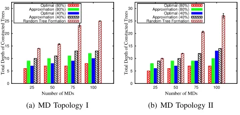
In Fig. 7, we compare the total depth of the constructed trees in scenarios with different number of MDs generated by three algorithms: The optimal algorithm is the solution from GUROBI or the modified-CTF problem. The approximation algorithm refers to Algorithm 1. In the random tree formation algorithm, every MD randomly selects a neighbor which has been included in a tree to be its parent. Also, in Fig. 7, two
cases are considered in both topologies, namely Nthreshold=
40%× |M| and Nthreshold=80%× |M|. For example, if we assume that every MD leaks the group key with
probabil-ity p=0.01 and |M|=100, then Nthreshold =40%× |M|
means we set the threshold probability Pthreshold =1−(1−
p)40%×|M|=1−(1−0.01)40%×100=0.331.
In Fig. 7, our approximation algorithm yields a total tree depth which is much smaller than that of the random tree formation algorithm while staying fairly close to the optimal
value. Also, as the maximum tree size (Nthreshold) increases,
both the optimal and the approximation algorithms tend to yield decreasing values of the total tree depth. This observation actually captures the inherent trade-off between efficiency and security of our optimization formulation. We will further demonstrate it in Fig. 9.
[image:5.612.316.561.294.412.2]|M| 25 50 75 100 Top. I Optimal 1.953 73.956 1418.134 6422.439 Top. I Approx. (40%) 0.048 1.892 12.309 15.319 Top. II Optimal 2.332 1650.730 6503.994 36009.112 Top. II Approx. (40%) 0.089 1.807 4.235 5.254
TABLE I
ALGORITHMCOMPLETIONTIME INSECONDS.
We can readily observe that completion time of the optimal algorithm increases exponentially with the number of MDs. In contrast, our approximation algorithm has much lower completion time.
Furthermore, from Table I, we observe that when |M|=
100, the optimal algorithm already has to take more than 6000s
to complete. This indicates that when solving the modified-CTF problem for a network of more than 100 MDs, it is better to turn to our approximation algorithm. Hence, we carry out simulation in scenarios with up to 300 MDs whereby our approximation algorithm terminates in reasonable time period. From Fig. 8, we can observe that the approximation rithm outperforms the baseline random tree formation
algo-25 50 75 100 125 150 175 200 225 250 275 300 10
20 30 40 50 60
Number of MDs
Total Depth of Constructed Trees
❘❛ ♥ ❞ ♦ ♠❚r ❡❡❋♦ r♠❛ t ✐ ♦ ♥ ❆♣ ♣r ♦①✐♠❛t✐ ♦ ♥✭ ✹ ✵✪ ✮
(a) MD Topology I.
25 50 75 100 125 150 175 200 225 250 275 300 10
20 30 40 50 60 70
Number of MDs
Total Depth of Constructed Trees
✁✂✄ ☎✆✝✞✟✟✠☎✞✆ ✁ ✡☛☎✂ ☞✌ ✌ ✞☎✍ ☛ ✆✁ ✡☛☎✂✎✏ ✑ ✒ ✓
[image:6.612.53.295.304.406.2](b) MD Topology II.
Fig. 8. Comparison of Total Tree Depth (Approximation vs. Random).
rithm in terms of the total tree depth when the number of MDs is larger than 100.
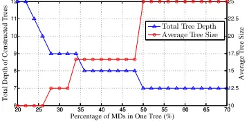
In Fig. 9, we fix the number of MDs to be |M|=50 and
vary the maximum percentage of MDs in one tree, Nthreshold
|M|
20 25 30 35 40 45 50 55 60 65 70 6
7 8 9 10 11 12
Total Depth of Constructed Trees
20 25 30 35 40 45 50 55 60 65 70 10 12.5 15 17.5 20 22.5 25
Percentage of MDs in One Tree (%)
Average Tree Size
✔✕✖✗❧✔✘✙✙❉✙✚✖❤ ✛✈✙✘✗❣✙✔✘✙✙❙✜③✙
Fig. 9. Efficiency and Security Tradeoff
from 20% to 70%. As this ratio increases, we see an increasing trend of the average constructed tree size and a decreasing trend of the total tree depth. This observation reflects the trade-off between efficiency and security of data collection inherently in our problem formulation. More specifically, if we allow MDs to form trees with larger sizes then the total depth of constructed trees tends to be smaller.
VI. CONCLUSION
In this paper, we develop a secure and efficient protocol to collect data from measurement devices (MD) in a multi-hop
manner through a mobile data collector (DC). MDs report data via trees rooted at the MDs that have direct communication with the DC. We formulate the secure and optimal tree construction problem as an integer linear programming, and develop an approximation algorithm to compute a solution. The simulations conducted using real topologies reflect that our algorithm performs well and efficiently.
REFERENCES
[1] N. Kayastha, D. Niyato, E. Hossain, and Z. Han, “Smart grid sensor data collection, communication, and networking: a tutorial,” Wireless Communications and Mobile Computing, pp. n/a–n/a, 2012.
[2] R. Tabassum, K. Nahrstedt, E. Rogers, and K.-S. Lui, “Scapach: Scalable password-changing protocol for smart grid device authentication,” in
IEEE ICCCN 2013, July 2013, pp. 1–5.
[3] V. Jain and G. Chapman, “Massively deployable intelligent sensors for the smart power grid,” inIEEE VLSI, Oct 2010, pp. 319–327. [4] M. Conti, A. Passarella, and L. Pelusi, “Mobile-relay forwarding in
opportunistic networks,” in Ch. 13 Adaptive Techniques in Wireless Networks. CRC Press, August 2008.
[5] S. Jain, R. Shah, W. Brunette, G. Borriello, and S. Roy, “Exploiting mobility for energy efficient data collection in wireless sensor networks,”
Mobile Networks and Applications, vol. 11, no. 3, pp. 327–339, 2006. [6] C. Konstantopoulos, G. Pantziou, D. Gavalas, A. Mpitziopoulos, and
B. Mamalis, “A rendezvous-based approach enabling energy-efficient sensory data collection with mobile sinks,” Parallel and Distributed Systems, IEEE Transactions on, vol. 23, no. 5, pp. 809–817, May 2012. [7] A. Bogdanov, E. Maneva, and S. Riesenfeld, “Power-aware base station
positioning for sensor networks,” inIEEE INFOCOM, March 2004. [8] R. Farahani and M. Hekmatfar, Facility Location: Concepts, Models,
Algorithms and Case Studies. Physica, 2009.
[9] A. A. Abbasi and M. Younis, “A survey on clustering algorithms for wireless sensor networks,” Computer Communications, vol. 30, no. 1415, pp. 2826 – 2841, 2007.
[10] A. Perrig, R. Szewczyk, J. D. Tygar, V. Wen, and D. E. Culler, “Spins: Security protocols for sensor networks,”Wirel. Netw., vol. 8, no. 5, pp. 521–534, Sep. 2002.
[11] G. Dan, K.-S. Lui, R. Tabassum, Q. Zhu, and K. Nahrstedt, “SELINDA: A secure, scalable and light-weight data collection protocol for smart grids,” inProc. of IEEE SmartGridComm, 2013.
[12] W. He, X. Liu, H. Nguyen, K. Nahrstedt, and T. Abdelzaher, “Pda: Privacy-preserving data aggregation in wireless sensor networks,” in
IEEE INFOCOM 2007, May 2007, pp. 2045–2053.
[13] W. He, H. Nguyen, X. Liu, K. Nahrstedt, and T. Abdelzaher, “iPDA: An integrity-protecting private data aggregation scheme for wireless sensor networks,” inIEEE MILCOM 2008, Nov 2008, pp. 1–7.
[14] T. Feng, C. Wang, W. Zhang, and L. Ruan, “Confidentiality protection for distributed sensor data aggregation,” inIEEE INFOCOM, April 2008. [15] M. Groat, W. He, and S. Forrest, “Kipda: k-indistinguishable privacy-preserving data aggregation in wireless sensor networks,” in IEEE INFOCOM, April 2011, pp. 2024–2032.
[16] Y. Yan, Y. Qian, and H. Sharif, “A secure and reliable in-network col-laborative communication scheme for advanced metering infrastructure in smart grid,” inIEEE WCNC, March 2011, pp. 909–914.
[17] K. Kursawe, G. Danezis, and M. Kohlweiss, “Privacy-friendly aggrega-tion for the smart-grid,” inPrivacy Enhancing Technologies. Springer, 2011, vol. 6794, pp. 175–191.
[18] F. Li, B. Luo, and P. Liu, “Secure information aggregation for smart grids using homomorphic encryption,” inIEEE SmartGridComm, 2010. [19] C. Rottondi, G. Verticale, and C. Krauss, “Distributed privacy-preserving aggregation of metering data in smart grids,”IEEE JSAC, vol. 31, no. 7, pp. 1342–1354, July 2013.
[20] H. Nicanfar, A. Alasaad, P. Talebifard, and V. Leung, “Network coding based encryption system for advanced metering infrastructure,” inIEEE ICCCN, July 2013, pp. 1–7.
[21] J. Cheriyan, S. Vempala;, and A. Vetta, “Network design via iterative rounding of setpair relaxations,”Combinatorica, vol. 26, pp. 255–275, 2006.
[image:6.612.85.265.483.576.2]