Doctoral Dissertations Student Theses and Dissertations
Summer 2016
Low-complexity iterative receiver algorithms for multiple-input
Low-complexity iterative receiver algorithms for multiple-input
multiple-output underwater wireless communications
multiple-output underwater wireless communications
Weimin Duan
Follow this and additional works at: https://scholarsmine.mst.edu/doctoral_dissertations
Part of the Electrical and Computer Engineering Commons
Department: Electrical and Computer Engineering Department: Electrical and Computer Engineering
Recommended Citation Recommended Citation
Duan, Weimin, "Low-complexity iterative receiver algorithms for multiple-input multiple-output underwater wireless communications" (2016). Doctoral Dissertations. 2509.
https://scholarsmine.mst.edu/doctoral_dissertations/2509
This thesis is brought to you by Scholars' Mine, a service of the Missouri S&T Library and Learning Resources. This work is protected by U. S. Copyright Law. Unauthorized use including reproduction for redistribution requires the permission of the copyright holder. For more information, please contact [email protected].
MULTIPLE-INPUT MULTIPLE-OUTPUT UNDERWATER WIRELESS COMMUNICATIONS
by
WEIMIN DUAN
A DISSERTATION
Presented to the Faculty of the Graduate School of the MISSOURI UNIVERSITY OF SCIENCE AND TECHNOLOGY
In Partial Fulfillment of the Requirements for the Degree DOCTOR OF PHILOSOPHY
in
ELECTRICAL ENGINEERING 2016
Approved by
Yahong Rosa Zheng, Advisor Randy H. Moss
Egemen K. C¸ etinkaya Maciej Zawodniok
PUBLICATION DISSERTATION OPTION
This dissertation consists of the following four published or to be published pa-pers, formatted in the style used by the Missouri University of Science and Technology, listed as follows:
Paper I, (pages 8–45) W. Duan, Y. R. Zheng,“Bidirectional Soft-Decision
Feedback Turbo Equalization for MIMO Systems”, has been accepted by
IEEE Trans. Veh. Technol., Aug. 2015.
Paper II, (pages 46–80) W. Duan, J. Tao and Y. R. Zheng,“Efficient Adap-tive Turbo Equalization for MIMO Underwater Acoustic Communications”, has been submitted to IEEE J. Ocean. Eng, Apr. 2016.
Paper III, (pages 81–96) W. Duan, Y. R. Zheng, D. Sun and Y. Zhang,“Block Iterative FDE for MIMO Underwater Acoustic Communications”, has been accepted by MTS/IEEE COA2016, Harbin, China, Jan. 9-11, 2016.
Paper IV, (pages 97–118) W. Duan, Y. R. Zheng,“Experimental Evaluation of Turbo Receivers in Single-Input Single Output (SISO) Underwater Acoustic Channels”, has been accepted by MTS/IEEE OCEANS, Shanghai, China, Apr. 11-14, 2016.
ABSTRACT
This dissertation proposes three low-complexity iterative receiver algorithms for multiple-input multiple-output (MIMO) underwater acoustic (UWA) communications. First is a bidirectional soft-decision feedback Turbo equalizer (Bi-SDFE) which harvests the time-reverse diversity in severe multipath MIMO channels. The Bi-SDFE outper-forms the original soft-decision feedback Turbo equalizer (SDFE) while keeping its total computational complexity similar to that of the SDFE. Second, this dissertation pro-poses an efficient direct adaptation Turbo equalizer for MIMO UWA communications. Benefiting from the usage of soft-decision reference symbols for parameter adaptation as well as the iterative processing inside the adaptive equalizer, the proposed algorithm is efficient in four aspects: robust performance in tough channels, high spectral efficiency with short training overhead, time efficient with fast convergence and low complexity in hardware implementation. Third, a frequency-domain soft-decision block iterative equalizer combined with iterative channel estimation is proposed for the uncoded single carrier MIMO systems with high data efficiency. All the three new algorithms are eval-uated by data recorded in real world ocean experiment or pool experiment. Finally, this dissertation also compares several Turbo equalizers in single-input single-output (SISO) UWA channels. Experimental results show that the channel estimation based Turbo equalizers are robust in SISO underwater transmission under harsh channel conditions.
ACKNOWLEDGMENTS
First and foremost, I would like to acknowledge my advisor Dr. Yahong Rosa Zheng. I sincerely appreciate her continuous support and devoted guidance throughout my Ph.D study. Without her numerous constructive suggestions, insightful comments and generous financial support, this dissertation would have been impossible. She has also provided me the opportunity to teach the wireless communication course, which improves my communication skills. Her enthusiasm, dedication and down-to-earth attitude towards research have set a role of academic perfection, from which I will benefit in my future research career.
My deep appreciation also goes to Dr. Chengshan Xiao for his guidance on my research work. He often share his experience in both research and career to teach me working smartly and efficiently, not only diligently. I also would like to thank Dr. Jun Tao for his generous assistance in research and technical writing. I enjoyed our collaborations and publications.
I would like to thank the members of my advisory committee, Drs. Randy H. Moss, Maciej Zawodniok, Egemen K. C¸ etinkaya and Maggie Cheng for generously offering their time and invaluable advice for my research.
I thank all the current and past members in the research lab for their kindly support and friendship. I cherish the time we spent together in Rolla.
I indebted my family for their unselfish love, everlasting support and sacrifice. Particularly, this dissertation is dedicated to my beloved wife, Qin Long and our smart, lovely baby girl, Sophie Siyong Duan. Last, but certainly not the least, I would like to express my eternal gratitude to my parents and parents-in-law for their unconditional love and support throughout the years.
TABLE OF CONTENTS
Page
PUBLICATION DISSERTATION OPTION . . . iii
ABSTRACT . . . iv ACKNOWLEDGMENTS . . . v LIST OF ILLUSTRATIONS . . . ix LIST OF TABLES . . . xi SECTION 1 INTRODUCTION . . . 1 1.1 BACKGROUND. . . 1 1.2 PROBLEM STATEMENT . . . 2 1.3 SUMMARY OF CONTRIBUTIONS . . . 4 1.4 REFERENCES . . . 6 PAPER I. BIDIRECTIONAL SOFT-DECISION FEEDBACK TURBO EQUALIZATION FOR MIMO SYSTEMS . . . 8
ABSTRACT. . . 8
1 INTRODUCTION . . . 9
2 SYSTEM DESCRIPTION . . . 12
3 PROPOSED BIDIRECTIONAL SDFE . . . 16
3.1 BIDIRECTIONAL SOFT-DECISION FEEDBACK EQUALIZER STRUCTURE . . . 16
3.2 SOFT-DECISION FEEDBACK EQUALIZERS FOR BI-SDFE. . . 18
3.3 EXTRINSIC INFORMATION COMBINING FOR BI-SDFE . . . 20
4 SIMULATION RESULTS . . . 25
5 CONVERGENCE ANALYSIS . . . 29
6 UNDERSEA EXPERIMENTAL RESULTS . . . 32
6.1 RESULTS OF 200 M UWA CHANNELS WITH SEVERE ISI . . . 35
6.2 RESULTS OF 1000 M UWA CHANNELS WITH IMPULSIVE INTER-FERENCE . . . 37
7 CONCLUSION. . . 40
8 ACKNOWLEDGEMENT . . . 41
II. EFFICIENT ADAPTIVE TURBO EQUALIZATION FOR MIMO
UNDERWATER ACOUSTIC COMMUNICATIONS . . . 45
ABSTRACT. . . 45
1 INTRODUCTION . . . 46
2 SYSTEM DESCRIPTION AND ADAPTIVE TURBO EQUALIZATION PRELIMINARY . . . 50
2.1 SYSTEM DESCRIPTION . . . 50
2.2 ADAPTIVE TURBO EQUALIZATION FOR MIMO SYSTEMS . . . 51
3 PROPOSED ADAPTIVE TURBO EQUALIZATION. . . 56
3.1 A POSTERIOR SOFT DECISION COMPUTATION IN THE EQUALIZER ITERATIONS . . . 57
3.2 A POSTERIOR SOFT DECISION BASED EQUALIZER ADAPTA-TION AND SIC . . . 58
3.2.1 A Posterior Soft Decision Based Equalizer Adaptation . . . 58
3.2.2 A Posterior Soft Decision Based SIC Scheme . . . 59
4 UNDERSEA EXPERIMENTAL RESULTS . . . 60
4.1 PARAMETER SETUP . . . 63
4.2 EXPERIMENTAL RESULTS . . . 64
4.2.1 Results On The Two-transducer MIMO Transmission . . . 64
4.2.2 Results On The MIMO Transmission With More Than Two Transducers . . . 67
4.2.3 Comparison Between The Proposed SD-DA-TEQ And The HD-DA-TEQ . . . 68
4.2.4 Evolutional Behavior Of The Proposed SD-DA-TEQ . . . 71
5 CONCLUSION. . . 75
6 ACKNOWLEDGEMENT . . . 76
7 REFERENCES . . . 77
III. BLOCK ITERATIVE FDE FOR MIMO UNDERWATER ACOUSTIC COMMUNICATIONS . . . 79
ABSTRACT. . . 79
1 INTRODUCTION . . . 80
2 SYSTEM MODEL . . . 82
3 BLOCK ITERATIVE RECEIVE SCHEME FOR MIMO SYSTEMS . . . 85
4 POOL EXPERIMENTAL RESULTS . . . 88
4.1 EXPERIMENTAL SETUP AND DATA FORMAT . . . 88
4.2 PERFORMANCE EVALUATION . . . 89
6 ACKNOWLEDGMENTS . . . 93
7 REFERENCES . . . 94
IV. EXPERIMENTAL EVALUATION OF TURBO RECEIVERS IN SINGLE-INPUT SINGLE-OUTPUT UNDERWATER ACOUSTIC CHANNELS . . . 95
ABSTRACT. . . 95
1 INTRODUCTION . . . 96
2 SYSTEM MODEL . . . 98
3 TURBO RECEIVER STRUCTURES . . . 100
3.1 CE-BASED LMMSE TURBO EQUALIZER. . . 101
3.2 CE-BASED SOFT-DECISION FEEDBACK TURBO EQUALIZER . . . . 102
3.3 CE-BASED BIDIRECTIONAL SOFT-DECISION FEEDBACK TURBO EQUALIZER . . . 103
3.4 SOFT-DECISION DIRECT-ADAPTATION TURBO EQUALIZER . . . . 103
4 EXPERIMENT DESCRIPTION . . . 105
5 PERFORMANCE EVALUATION . . . 107
5.1 CE-BASED TURBO EQUALIZATIONS . . . 107
5.2 SOFT-DECISION DIRECT-ADAPTATION TURBO EQUALIZATION 109 6 CONCLUSION. . . 112 7 ACKNOWLEDGEMENT . . . 113 8 REFERENCES . . . 114 SECTION 2 CONCLUSIONS . . . 116 3 PUBLICATIONS . . . 118 VITA . . . 119
LIST OF ILLUSTRATIONS
Figure Page
PAPER I
2.1 Structure of a MIMO communication system with turbo equalizer. . . 13
3.1 Block Diagram of the Proposed MIMO Bi-SDFE . . . 16
4.1 Extrinsic LLR distribution of the equalizer output. . . 26
4.2 BER performance of different Turbo equalizers for a 2×2 MIMO system over a five-tap ISI channel. . . 27
5.1 Three dimensional EXIT charts for the proposed Bi-SDFE and the original SDFE. . . 30
5.2 Two dimensional EXIT chart for 16QAM at SNR = 31 dB. . . 31
6.1 The format of transmission packet in the SPACE08 experiment . . . 33
6.2 Examples of channel impulse response over long term observation. . . 34
6.3 Examples of received signals in 200 m and 1000 m transmissions. . . 35
6.4 Performance comparison between the Bi-SDFE and the SDFE for 2×6 MIMO over 200 m UWA channels.. . . 37
6.5 Performance comparison between the Bi-SDFE and the SDFE for 2×6 MIMO over 1000 m UWA channels. . . 39
PAPER II 2.1 The block diagram of a MIMO underwater acoustic communication system. 50 2.2 The structure of the adaptive turbo equalization for MIMO systems. . . 52
2.3 The block diagram of the hard-decision adaptive equalizer with data reuse. 54 3.1 The block diagram of the proposed adaptive equalizer with data reuse. . . 56
4.1 Format of the transmit signal on the n-th transducer in the SPACE08 experiment. . . 61
4.2 An example of the received signals in 200-m and 1000-m transmissions.. . . 62
4.3 An example of the channel impulse responses over a period of time. . . 63
4.4 Detection results of the two-transducer MIMO transmission after 5 turbo iterations. . . 66
4.5 The MSE curves of the 2×6 MIMO detection with 8PSK and 16QAM
modulations. . . 67
4.6 Detection results of the 3×12 MIMO transmission after 5 turbo iterations. 68 4.7 Detection results of the 4×12 MIMO transmission after 5 turbo iterations 69 4.8 BER comparison between the SD-DA-TEQ and the HD-DA-TEQ for 2×6 MIMO transmission . . . 70
4.9 BER range comparison between the SD-DA-TEQ and the HD-DA-TEQ after 1 and 3 turbo iterations for 2×6 MIMO transmission. . . 70
4.10 MSE comparison between the SD-DA-TEQ and the HD-DA-TEQ for 2×6 MIMO transmission . . . 71
4.11 The evolution of soft decisions. . . 72
4.12 The MSE evolution of the IPNLMS-based SD-DA-TEQ. . . 73
4.13 Performance evolution of the NLMS-based SD-DA-TEQ . . . 74
PAPER III 3.1 Structure of the proposed iterative receiver. . . 85
4.1 The data structure in the pool experiment. . . 88
4.2 An example channel in the pool experiment. . . 89
4.3 An example of performance improvement in the IB-FDE process. . . 90
4.4 BER ranges comparison with different number of iterations (block size 2048, 2×4 MIMO UWA channels). . . 90
4.5 BER ranges comparison with different number of iterations (block size 4096, 2×4 MIMO UWA channels). . . 91
PAPER IV 2.1 Block diagram of the single transmitter UWA communication system. . . 98
3.1 Block diagram of the Turbo receiver for SISO UWA communication system. 100 4.1 The burst structure of thenth transmit branch in the SPACE08 experiment.106 4.2 CIRs over one packet transmission. . . 106
5.1 BER performance of CE-based TEQs. Packet 7 reached 0 BER for all algorithms with Iter 0 in QPSK and 8PSK transmissions. . . 108
5.2 BER performance of Soft-Decision DA-TEQ. Packet 7 achieved 0 BER at Iter 0 for all modulation schemes. . . 110
LIST OF TABLES
Table Page
PAPER I
6.1 Number of packets that achieves the specified BER performance (2×6 MIMO
over 200 m channels). . . 36
6.2 Number of packets that achieves the specified BER performance (2×6 MIMO
over 1000 m channels). . . 38 PAPER II
4.1 Description of the Hydrophone Arrays . . . 60 4.2 List of training overheads (block sizes) and the corresponding data rates
for different combinations of modulation and MIMO size . . . 64 4.3 Number of packets achieving the specified BER level (2×6 MIMO) . . . 65
1 INTRODUCTION
1.1 BACKGROUND
Underwater wireless communications have played an important role in the wide range of oceanic engineering applications, such as environmental monitoring, offshore exploration, and disaster prevention. Particularly, acoustic communications are con-sidered as the most effective means for medium and long range underwater communi-cations, although optical and magneto-inductive systems may also be suited for short range underwater communications [1]. However, current underwater acoustic (UWA) communication systems can only achieve very low data rates such as 1 kbps to 10 kbps at medium range (1 km to 10 km) due to the limited channel bandwidth.
Recently, the multiple-input multiple-output (MIMO) technology has been con-sidered in UWA communication systems to increase the data rate without additional bandwidth or transmit power [2, 3]. The MIMO systems employ multiple elements at both the transmitter and receiver sides. Theoretically, the MIMO channel capacity grows linearly with the minimum number of transmit and receive antennas. However, the practical application of MIMO technology to achieve reliable underwater high-data-rate transmission still exhibits unique technical challenges. Typically, UWA MIMO channels are severe triply-selective, which simultaneously experience frequency selec-tivity, temporal selecselec-tivity, and spatial selectivity. The severe frequency selectivity is caused by the extremely long multipath delay spread, which results in severe inter-symbol interference (ISI). The time selectivity is due to the large doppler spread, which causes high carrier frequency offest (CFO) and waveform compression or depression. The spatial selectivity means the strong spatial correlation among multiple transmit
and receive elements, and the resulting co-channel interference further challenges the robust symbol detection.
Turbo equalization is a promising detection scheme to achieve near optimal per-formance in MIMO UWA communications. Typical turbo equalizers consist of two components: a soft-input soft-output (SISO) equalizer and a SISO decoder, which iter-atively exchanges extrinsic information with each other. The optimal Turbo equalizer was designed with a maximum a posteriori probability (MAP) equalizer and a MAP decoder [4]. However, the complexity of the MAP based Turbo equalizer grows expo-nentially with the product of the MIMO size and channel length, which is prohibitively high in extremely long delayed UWA channels. To greatly lower the computational complexity, the Minimum Mean Square Error (MMSE) based Turbo Equalizers have been proposed [5, 6, 7]. Currently, two classes of MMSE turbo equalizers are commonly used in UWA communications: channel estimation based MMSE turbo equalizer (CE TEQ) [3] and direct adaptation turbo equalizer (DA-TEQ) [12]. In CE MMSE-TEQ, the UWA channel is explicitly estimated and incorporated into the calculation of MMSE equalizer coefficients. Alternatively, the DA-TEQ uses adaptive algorithms to directly equalize the received symbols without the knowledge of the UWA channel.
1.2 PROBLEM STATEMENT
The existing CE MMSE-TEQs can be roughly classified into two categories. First, Turbo MMSE Linear Equalizers (LE) have been proposed in [5, 6, 7]. The exact implementation of the Turbo MMSE LE is capable of approaching the performance of MAP equalizer, but requires equalizer coefficients computation at each symbol, re-sulting in a time-varying equalizer whose complexity is quadratic with the MIMO size and the equalizer length, which is prohibitively high for UWA communications. The approximate implementation of Turbo MMSE LE (approximate Turbo LE) with no a priori information only updates the equalizer coefficients once at each block. Hence the approximate Turbo LE achieves complexity that is a linear function of the product of
the MIMO size and equalizer length. However, the approximate Turbo LE requires a large number of iterations to converge in tough channels, which leads to long latency and may be impractical in real-time applications.
Second, Turbo decision feedback equalizers (DFE) have been proposed for severe ISI channels, which exhibit the advantages of low complexity and fast convergence [8,11,9,10]. Especially, for harsh channels with deep spectral nulls, Turbo DFEs exhibit less noise enhancement and better Bit-Error-Rate (BER) performance than Turbo LEs. For example, the soft-decision feedback Turbo equalizer (SDFE) [9, 10] achieves good performance in severe ISI channels while its complexity is a linear function of the product of the MIMO size and channel length. In single-input single-output (SISO) systems with multilevel modulations, the SDFE even achieves better performance with lower complexity, lower Signal-to-Noise-Ratio (SNR) threshold and faster convergence than the exact Turbo LE [9]. However, the SDFE suffers from a higher error floor than the exact Turbo LE at high SNR region. Besides, the SDFE only considers the causal feedback and ignores the residual anti-causal ISI, which limits its performance in severe triply selective MIMO UWA channels [10].
In CE MMSE-TEQ, the UWA channel is explicitly estimated for the calculation of MMSE equalizer coefficients. The performance of the CE MMSE-TEQs have been verified by many oceans experiments [2, 3]. However, due to the typically long channel impulse response, the large-dimension matrix inversion involved in the equalizer coeffi-cients computation contributes greatly to the overall receiver complexity. Alternatively, the DA-TEQ greatly lowers the complexity of the receiver by using the adaptive algo-rithms to directly estimate the coefficients of the equalizer without matrix inversion op-eration [12]. In most existing DA-TEQs, equalizer coefficient adaptation is performed with the decision-directed (DD) method after the training phase. At the DD mode, the current tentative hard decision at the output of the equalizer is used to drive the adaptation of the equalizer coefficients. Such an empirical processing method is widely used in existing UWA communication systems employing adaptive turbo equalizers.
The main drawback of the hard decision directed adaptation is the error propagation, which may results into a catastrophic failure of the convergence. Especially in fast time varying MIMO UWA channels, due to the higher probability of incorrect symbol decision and extremely long equalizer length, the error propagation effect is further amplified.
Motivated by the respective advantages and limitations of the methods in the literature, we proposed several low-complexity receiver algorithms to enable robust MIMO UWA communications.
1.3 SUMMARY OF CONTRIBUTIONS
This dissertation consists of a couple of journal publications and conference papers listed in the publication list. My contributions that are published or under review are:
1. This dissertation proposes a bidirectional soft-decision feedback turbo equal-ization (Bi-SDFE) for MIMO Systems. The proposed Bi-SDFE incorporates the bidi-rectional structure with two parallel SDFEs: a time-reversed SDFE and a normal SDFE. To harvest the time-reverse diversity in MIMO systems with multilevel modulations, a simple and effective linear combining scheme is derived to combine the extrinsic information at the outputs of the two SDFEs. Both BER simulation results and Ex-trinsic Information Transfer (EXIT) chart analysis show that the Bi-SDFE achieves significant performance improvement over the original SDFE without increasing com-putation complexity. Moreover, the Bi-SDFE even outperforms the well-known exactly implemented Turbo LE at medium-to-high SNR region. The obvious performance gain of the proposed Bi-SDFE has been verified through a real world underwater acoustic communication experiment with tough channel conditions.
2. A efficient DA-TEQ scheme is proposed for MIMO UWA communications. Compared with existing DA-TEQs, the proposed DA-TEQ scheme is enhanced through using thea posterior soft decisions as the reference symbols for filter adaptation as well
as the iterative processing inside the adaptive equalizer itself. The proposed DA-TEQ is efficient in four aspects: first, it achieves robust performance in tough MIMO UWA channels with extremely long delay spread, fast time variation and strong spatial corre-lation; second, it exhibits high spectral efficiency by requiring relatively short training overhead; third, the proposed adaptive turbo receiver converges rapidly in the highly dispersive MIMO UWA channels, thus is time efficient; fourth, it is computationally ef-ficient by adopting the low complexity adaptive algorithm without matrix inversion op-eration. The aforementioned efficiencies of the proposed DA-TEQ have been verified by the experimental data collected in the 2008 Surface Processes and Acoustic Communica-tions Experiment (SPACE08). Both the normalized least mean square (NLMS) and the sparsity enhanced improved proportionate normalized least mean squares (IPNLMS) algorithm are tested in the proposed turbo receiver. Moreover, the proposed scheme achieves satisfactory performance even in MIMO transmission with multilevel modula-tions and more than two concurrent data streams, which has not been reported for any existing DA-TEQs.
3. A low complexity frequency domain iterative detection scheme is proposed for the uncoded zero padding (ZP) single carrier (SC) transmission in MIMO UWA chan-nels. A soft-decision block iterative frequency-domain equalization (BI-FDE) combined with iterative channel estimation is designed to enhance the performance of the ZP SC systems with high data efficiency. Benefiting from the iteratively increased quality of symbol detection and channel estimation, the proposed BI-FDE achieves obvious perfor-mance gain over the non-iterative FDE. The perforperfor-mance enhancement of the proposed iterative receiver has been verified through a pool test. Moreover, since both the feed-foward and feedback filters are designed in frequency domain without channel coding, the proposed iterative receive scheme is promising for hardware implementation.
4. This dissertation also evaluates the CE MMSE-TEQs and the DA-TEQ in single-input single-output (SISO) UWA channels. For CE MMSE-TEQ, the recently proposed Bi-SDFE is compared with the SDFE and the approximate Turbo LE in terms
of the BER performance. For DA-TEQ, the recently proposed soft-decision DA-TEQ is evaluated with the same set of experimental data. The field trial data collected in SPACE08 experiment are used in the performance evaluation. Experimental results show that the CE-TEQs are robust in SISO underwater acoustic transmission under tough channel conditions. With low pilot overheads, the recently proposed Bi-SDFE achieved lowest BER performance in all cases with slightly higher computational com-plexity. For QPSK modulation, all CE-TEQs and DA-TEQ are capable to achieve extraordinary low BER performance for in all packets.
1.4 REFERENCES
[1] M. Stojanovic and J. Preisig, “Underwater acoustic communication channels: Prop-agation models and statistical characterization,” IEEE Commun. Mag., vol. 47, no. 1, pp. 84–89, Jan. 2009.
[2] J. Tao, Y. R. Zheng, C. Xiao, and T. Yang, “Robust MIMO underwater acous-tic communications using turbo block decision-feedback equalization,” IEEE J. Oceanic Eng., vol. 35, no. 1, pp. 90–99, Jan. 2010.
[3] Z. Yang and Y. R. Zheng, “Iterative channel estimation and turbo equalization for multiple-input multiple-output underwater acoustic communications,” IEEE J. Ocean. Eng., vol. 41, no. 41, pp. 232–242, Jan. 2016.
[4] C. Douillard, M. J´ez´equel, C. Berrou, D. Electronique, A. Picart, P. Didier, and A. Glavieux, “Iterative correction of intersymbol interference: Turbo-equalization,” European Trans. Telecommun., vol. 6, no. 5, pp. 507–511, May 1995.
[5] M. Tuchler, R. Koetter, and A. C. Singer, “Turbo equalization: principles and new results,” IEEE Trans. Commun., vol. 50, no. 5, pp. 754–767, May 2002.
[6] M. Tuchler, A. C. Singer, and R. Koetter, “Minimum mean squared error equal-ization using a priori information,”IEEE Trans. Signal Process., vol. 50, no. 3, pp. 673–683, Mar. 2002.
[7] T. Abe, S. Tomisato, and T. Matsumoto, “A MIMO turbo equalizer for frequency-selective channels with unknown interference,” IEEE Trans. Veh. Technology, vol. 52, no. 3, pp. 476–482, Mar. 2003.
[8] R. R. Lopes and J. R. Barry, “The soft-feedback equalizer for turbo equalization of highly dispersive channels,”IEEE Trans. Commun., vol. 54, no. 5, pp. 783–788, May 2006.
[9] H. Lou and C. Xiao, “Soft-decision feedback turbo equalization for multilevel mod-ulations,” IEEE Trans. Signal Process., vol. 59, no. 1, pp. 186–195, Jan. 2011.
[10] A. Rafati, H. Lou, and C. Xiao, “Low-complexity soft-decision feedback turbo equalization for MIMO systems with multilevel modulations,” IEEE Trans. Veh. Technology, vol. 60, no. 7, pp. 3218–3227, Jul. 2011.
[11] J. Wu and Y. R. Zheng, “Low complexity soft-input soft-output block decision feedback equalization,” IEEE J. Sel. Areas Commun., vol. 26, no. 2, pp. 281–289, Feb. 2008.
[12] J. W. Choi, T. J. Riedl, K. Kim, A. C. Singer, and J. C. Preisig, “Adaptive linear turbo equalization over doubly selective channels,” IEEE J. Ocean. Eng., vol. 36, no. 4, pp. 473–489, Oct. 2011.
PAPER
I. BIDIRECTIONAL SOFT-DECISION FEEDBACK TURBO EQUALIZATION FOR MIMO SYSTEMS
Weimin Duan and Yahong Rosa Zheng, Fellow, IEEE
ABSTRACT—This paper proposes a bidirectional soft-decision feedback Turbo
equal-izer (Bi-SDFE) for severe triply-selective fading channels. The proposed Bi-SDFE uses a time-reversed soft-decision feedback equalizer (SDFE) in conjunction with a normal SDFE to harvest time-reverse diversity and mitigate error propagation. A simple and effective linear combining scheme is derived for combining the extrinsic information of the two SDFEs for multiple-input multiple-output (MIMO) systems with both Binary Phase Shift Keying (BPSK) and multilevel modulation. The Bit-Error-Rate (BER) simulation results show that the proposed Bi-SDFE exhibits a lower Signal-to-Noise-Ratio (SNR) threshold than the original SDFE and outperforms the well-known Exact Turbo Minimum Mean Square Error (MMSE) Linear Equalizers at medium-to-high SNRs. Moreover, both Extrinsic Information Transfer (EXIT) chart analysis and BER simulation results show that the Bi-SDFE achieves better performance than the orig-inal SDFE while the Bi-SDFE uses only half the number of iterations of the SDFE. Therefore, the total computational complexity of the Bi-SDFE is similar to that of the original SDFE, which is a linear function of the channel length, MIMO size, and modulation constellation size. The performance gain of the proposed Bi-SDFE is also verified through an underwater acoustic communication experiment with tough channel conditions.
1 INTRODUCTION
Multiple-input-multiple-output (MIMO) communication technology has long been recognized as an essential part of high performance wireless communication systems [1]. However, robust MIMO receiver design still exhibits unique technical challenges, espe-cially in severe triply-selective MIMO channels [2]. By severe triply-selective channel, we mean those MIMO channels that simultaneously experience frequency selectivity, tem-poral selectivity, and spatial selectivity. Severe frequency selectivity means extremely long delay spread. Temporal selectivity is caused by large Doppler spread and spa-tial selectivity is due to angular spreads among multiple transmit elements or among multiple receive elements. Examples of such channels include applications of mobile television receivers [3], underwater acoustic (UWA) MIMO communications [4, 5], and high data-rate communications involving multiple MIMO relays [6].
Turbo equalization is an effective means to achieve near optimal detection for MIMO triply-selective channels with affordable computational complexity. The maxi-mum a posteriori probability (MAP) equalizer and MAP decoder were adopted in the initially proposed Turbo equalizer [7]. However, the complexity of the MAP equalizer grows exponentially with the product of the MIMO size and channel length, which is prohibitively high in severe triply-selective channels. To reduce the computational com-plexity, Turbo Minimum Mean Square Error (MMSE) Linear Equalizers (LE) have been designed [8, 9, 10]. Especially, the low-complexity Turbo LE can achieve a complexity that is a linear function of the product of the MIMO size and channel length. However, the low-complexity Turbo LE requires a large number of iterations to converge, which leads to long processing time and may be impractical in real-time applications.
Recently, Turbo decision feedback equalizers (DFE) have been proposed for se-vere ISI channels, which exhibit the advantages of low complexity and fast conver-gence [11,12,13,14]. Especially, for harsh channels with deep spectral nulls, Turbo DFEs
exhibit less noise enhancement and better Bit-Error-Rate (BER) performance than Turbo LEs [1]. For example, the soft-decision feedback Turbo equalizer (SDFE) [13,14] achieves good performance in severe ISI channels while maintaining linear computa-tional complexity. In single-input single-output (SISO) systems with multilevel modu-lations, the SDFE [13] achieves better performance with lower complexity, lower Signal-to-Noise-Ratio (SNR) threshold and faster convergence than the exact Turbo LE [9]. However, the SDFE suffers from a higher error floor than the exact MMSE-LE at high SNRs. In addition, the SDFE only includes causal feedback and ignores the residual interference from anti-causal symbols, which limits its performance in MIMO channels with severe ISI and co-channel interference [14].
Interestingly, a bidirectional structure has been developed for decision feedback equalizer to improve its performance by utilizing a time-reversed DFE in combination with a normal DFE [15, 16, 17, 18, 19, 20, 21, 22]. Bidirectional equalizers were first introduced for hard-decision DFEs [15, 16, 17] to reduce error propagation inherent to DFEs. It was shown [18] that the bidirectional structure can also harvest the diversity provided by the two DFEs because the past symbols are known to the normal DFE and the future symbols are known to the time-reversed DFE. The diversity not only reduces error propagation, but also lowers noise enhancement because the noise of the two DFEs have low correlation. This hard-decision bidirectional DFE is used in a time reversal UWA communication system as a post processor [19] while the time-reversal filters are used for pre-processing. The work in [23] introduces an arbitration mechanism with filtering to exploit the error distributions at the outputs of the normal and time-reversed DFEs. Later, the bidirectional structure is applied in trellis-based delayed decision feedback soft-output turbo equalizers [20, 21] which combines the soft symbols of the two DFEs in each iteration and feeds the combined symbols to the decoder. More recently, a low-complexity soft-input soft-output bidirectional DFE (Bi-DFE) [22] combines extrinsic information instead of soft symbols of the two DFEs. The performance of the soft Bi-DFE [22] is said to approach that of MAP equalizers for
Binary Phase Shift Keying (BPSK) after a large number of iterations. However, most of the existing Bi-DFE schemes [15,16,17,18,19,20,21,22] are investigated for single-input single-output systems and use hard-decision symbols as the input to the feedback filter. In addition, the Bi-DFE in [22] is based on a modified hard-decision turbo DFE which has to estimate the probability of error sequences, thus exhibiting high computational load when the number of feedback filter taps or the size of the signal constellation is large.
In this paper, we propose a bidirectional SDFE (Bi-SDFE) that incorporates the bidirectional structure with the SDFE for MIMO systems. The proposed Bi-SDFE scheme utilizes the soft symbols in both feed-forward and feedback filtering and ex-tends the extrinsic information combining scheme to MIMO systems with multilevel modulation. We derive a simple and effective linear combining scheme to explore the time-reverse diversity in the two sets of SDFE outputs for severe triply-selective chan-nels. The computational complexity of the Bi-SDFE is slightly higher than the original SDFE because the Bi-SDFE uses only half the number of iterations required by the orig-inal SDFE. The overall complexity of the proposed Bi-SDFE and the origorig-inal SDFE remains a linear function of the channel length, constellation size, and MIMO size. The BER performance and convergence property of the proposed Bi-SDFE are demonstrated by computer simulations and Extrinsic Information Transfer (EXIT) chart analysis. In addition, we verify the performance of the Bi-SDFE using field test data collected in an undersea acoustic communication experiment, where the MIMO channels exhibit not only severe ISI and Doppler spread, but also impulsive interference. Results of the real-world experiment show that the proposed Bi-SDFE achieves consistent improvement of BER performance over the original MIMO SDFE [14].
Throughout this paper, we use the following notational conventions: superscripts (·)T and (·)H represent matrix transpose and conjugate transpose, E{·}denotes statis-tical expectation and diag(a1,· · ·, ak) denotes a diagonal matrix with a1,· · · , ak being the diagonal entries.
2 SYSTEM DESCRIPTION
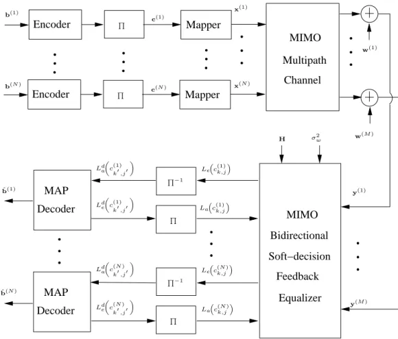
We consider an N ×M MIMO communication system depicted in Fig. 2.1,
whereN andM are the numbers of transmit and receive elements, respectively. At the transmitter, the information bit sequence is converted intoN parallel streams{b(n)}N
n=1.
Each bit stream is then independently encoded, interleaved, and modulated. The output of the nth interleaver is grouped as a length-Kc block c(n) =
h
c(1n) c(2n)· · ·c(Kn)
c
i
where ck(n) represents the kth bit vector hck,(n1) c(k,n2)· · ·ck,q(n)i with the jth bit ck,j(n) ∈ {0,1}. The mapper then maps each bit vector c(kn) to a symbol x(kn) from the 2q−ary constellation set S = {α1, α2,· · · , α2q}, where αi corresponds to the deterministic bit pattern si =
[si,1 si,2· · ·si,q] with si,j ∈ {0,1}, which specifies the mapping between the interleaved encoded bits and the elements of the constellation. After symbol mapping, the baseband signal is partitioned into blocks and modulated with a single carrier, then transmitted to the MIMO multipath channel.
On the receiver side, the received signals are demodulated and sampled to yield symbol rate baseband signals. The baseband signal at themth receive element at time instant k can be written as
yk(m)= N X n=1 L−1 X l=0 h(lm,n)xk(n−)l+w(km) (1)
wherex(kn−)l is the symbol transmitted by thenth transmit element at time instant k−l
and h(lm,n) is the lth coefficient of the baseband equivalent channel between the nth transmitter and themth receiver. In addition,Lis the length of the baseband equivalent channel, andwk(m) represents the noise sample at themth receiver, which is assumed to be zero mean additive white Gaussian noise (AWGN) with variance σ2
Decoder MAP Decoder MAP Mapper Mapper Encoder Encoder MIMO Multipath Channel Feedback Soft−decision Bidirectional MIMO Equalizer b(1) b(N) c(1) c(N) x(1) x(N) y(1) y(M) Le c(1)k,j Lda c(1) k′,j′ La c(1)k,j Ld e c(1) k′,j′ Le c(N)k,j Lda c(N) k′,j′ La c(N)k,j Lde c(N) k′,j′ Q Q Q Q Q−1 Q−1 ˆ b(1) ˆ b(N) w(1) w(M) H σ2w
Figure 2.1. Structure of a MIMO communication system with turbo equalizer.
the received symbols at all M receiver antennas asyk = [y (1) k , y (2) k , . . . , y (M) k ] T , we have yk= L−1 X l=0 hlxk−l+wk (2) where xk= [x(1)k , xk(2), . . . , x(kN)]T (2a) wk= [w(1)k , w (2) k , . . . , w (M) k ] T (2b)
yk−N2 .. . yk .. . yk+N1 | {z } Yk = hL−1 · · · h0 · · · 0 .. . . .. ... ... ... . .. ... ... ... 0 · · · hL−1 · · · h0 | {z } H × xk−N2−L+1 .. . xk .. . xk+N1 | {z } Xk + wk−N2 .. . wk .. . wk+N1 | {z } Wk (4) and hl = h(1l ,1) h(1l ,2) · · · h(1l ,N) h(2l ,1) h(2l ,2) · · · h(2l ,N) ... ... . .. ... h(lM,1) h(lM,2) · · · h(lM,N) . (2c)
Therefore, the space-time representation of the MIMO system is given by
Yk=HXk+Wk (3)
where Yk, H, Xk and Wk are defined in (4). Note that Yk, Xk and Wk are the concatenated column vectors with elements defined in (2), (3) and (4), respectively. The observation window lengths N1 and N2 denote the causal and noncausal parts, respectively, of the received symbols at time instant k which are determined by the location of the strongest tap of the channel impulse response with respect to the other taps.
The iterative equalization and decoding process is also depicted in Fig. 2.1, where the MIMO Bi-SDFE estimates the symbols ˆx(kn) block by block, and outputs the corresponding extrinsic information of the transmitted bits Le
information is then passed to the de-interleaver, and the de-interleaved extrinsic infor-mation Le
c(kn′,j)′
is treated as the a priori information Ld a
c(kn′)
,j′
for MAP decoding. After decoding, the decoder outputs its extrinsic informationLd
e c(kn′) ,j′ , which is further fed back to the equalizer (after interleaving) as thea priori informationLa
c(k,jn)of the transmitted bit sequence. Based on the turbo principle, the extrinsic information and the a priori information are exchanged between the equalizer and decoder iteratively with the reliability of the soft information increasing with the number of iterations. The final hard decision ˆb(kn) is made after multiple iterations or after the decoder output converges.
3 PROPOSED BIDIRECTIONAL SDFE
In this section, a MIMO Bi-SDFE scheme with multilevel modulation is devel-oped.
3.1 BIDIRECTIONAL SOFT-DECISION FEEDBACK EQUALIZER STRUCTURE
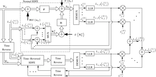
The structure of the proposed Bi-SDFE is depicted in Fig. 3.1, where two SDFEs run in parallel: one is a normal SDFE with details illustrated in the dashed box, the other is a time-reversed SDFE whose internal structure is the same as the normal SDFE. Note, time reverse here refers to the operation of blockwise sequence flipping in time without filtering, which is slightly different from the concept of time reversal in underwater acoustic communications [24]. The log likelihood ratio (LLR) outputs of the two SDFEs, denoted as Le,f
c(k,jn) and Le,b
c(k,jn) for n = 1,· · · , N, are combined via the weighting factorsλ(j,fn) and λ(j,bn), respectively.
At the front end of the time-reversed SDFE, the received sequence yk and the
DEMUX Reverse Time SDFE Time−Reversed Time Reverse Time Reverse DEMUX MUX Normal SDFE LLR LLR LLR LLR La c(n)k,j ˜ La c(n)k,j HE{xk} F B Le,fc(1)k,j Le,f c(N)k,j Le,b c(N)k,j Le,b c(1)k,j Le c(N)k,j Le c(1)k,j λ(1)j,f λ(N)j,f λ(N)j,b λ(1)j,b Yk ˜ Yk La c(1)k,j La c(N)k,j Lc(1)k,j Lc(N)k,j ˆ x(1)k ˆ x(N)k ˆ xk Xdk EnXdko E{xk}
channel impulse response matrix h are both flipped, resulting in an equivalent time-reversed baseband discrete model
˜ yk = L−1 X l=0 ˜ hlx˜k−l+ ˜wk (5) where ˜ yk = [y (M) Kc−k+1, y (M−1) Kc−k+1, . . . , y (1) Kc−k+1] T (5a) ˜ xk = [x(1)Kc−k+1, x(2)Kc−k+1, . . . , x( N) Kc−k+1] T (5b) ˜ wk = [w( M) Kc−k+1, w (M−1) Kc−k+1, . . . , w (1) Kc−k+1] T (5c) and ˜ hl = h(LM,−l1)+1 hL(M,−l2)+1 · · · h(LM,N−l+1) hL(M−−l+11,1) h(LM−−l+11,2) · · · h(LM−−l+11,N) .. . ... . .. ... h(1L−,1)l+1 hL(1−,2)l+1 · · · h(1L−,Nl+1) . (5d)
Rewriting the time-reversed system model (5) into matrix form, we have
˜
Yk= ˜HX˜k+ ˜Wk (6)
where ˜Yk, ˜H and ˜Xk are defined in a similar manner as in (4), but with the time-reversed signals ˜yk, ˜xk, ˜wk, and the time-reversed channel impulse response ˜hl.
The equivalent channel impulse response in the time-reversed system model (5d) is the time reverse of the original channel impulse response, which results in reversed root locations, i.e.,the minimum phase roots of the original channel response become the maximal phase roots of the time-reversed channel and vice-versa. This property partially explains the performance improvement of the Bi-SDFE over the original SDFE in two aspects. First, if the channel is asymmetric, then the equivalent time-reversed channel is different from the original channel, which results in different error patterns
at the outputs of the normal SDFE and the time-reversed SDFE. The low correlation of the error locations at the output of the two SDFEs provides diversity which can be exploited to improve system performance. Second, without an anti-causal feedback filter, the original SDFE is inefficient at removing the precursor ISI. However, with the bidirectional structure, past symbols are detected by the normal SDFE, and future symbols are available from the time-reversed SDFE, thus Bi-SDFE can effectively cancel both precursor ISI and postcursor ISI.
3.2 SOFT-DECISION FEEDBACK EQUALIZERS FOR BI-SDFE
The SDFEs in the proposed Bi-SDFE are modified from the original SDFE [13], [14]. The original SDFE is a mixed soft-decision DFE which adopts a linear equalizer in the first iteration and utilizes soft DFE in the subsequent iterations. However, the proposed Bi-SDFE uses soft DFE in all iterations because the bidirectional structure can effectively reduce error propagation, resulting in better performance than a linear equalizer, especially in severe ISI channels with deep spectrum nulls.
The SDFE consists of a feedforward filter Fk ∈ CN×M(N1+N2+1) and a feedback filter Bk ∈ CN×(N N3), where N3 = N2 +L −1. The feedback filter is designed to cancel the residual causal ISI after feedforward filtering, and the time-varying offsetdk compensates for a possibly nonzero mean of the data symbols. Based on this SDFE structure, the estimated symbol ˆxk is expressed as
ˆ
xk=FkYk+BkXdk+dk (7)
whereYk is defined in (4) and
Xdk =xdk−N3,xdk−N3+1,· · · ,xdk−1T (7a) xdk =h(x(1)k )d,(x(2)k )d,· · · ,(x(kN))diT . (7b)
Here the superscript (·)d denotes the operation of soft decision based on the a posteriori information Lc(k,jn). That is
x(kn)d=X αi∈S αiP ˜ x(kn)d=αi (8) P x˜(kn)d=αi = q Y j=1 1 2 1+˜si,jtanh Lc(k,jn) 2 (9) where ˜ si,j = +1, if si,j = 0 −1, if si,j = 1 and Lc(k,jn)=La c(k,jn)+Le c(k,jn). (10)
In this paper, we use the low-complexity SDFE for the Bi-SDFE, which is imple-mented by forcing the related covariance matrices to be time invariant. The coefficients of the feedforward and feedback filter in the low-complexity SDFE are only updated at every iteration rather than for each time instance k. Therefore we drop the subscript
k and design the filters of the SDFE [14] as
FH=σ2 wINo+H C f f−Cf b(Cbb)−1(Cf b)HHH−1s (11) BH=− Cbb−1 HCf bHFH (12) dk=E{xk} −FHE{Xk} −BE Xdk (13)
whereCff,Cf b and Cbb are the covariance matrices defined as
Cf f =EXkXHk −E{Xk}E XHk (14a) Cf b=EnXkXdk Ho −E{Xk}E n XdkHo (14b) Cbb=EnXdkXdkHo−EXdk EnXdkHo (14c)
which are computed by the a priori information and the a posteriori information, as detailed in [14], and s=H[0N×(N(N2+L−1)) IN 0N×(N N1)]
T is the selection vector. Note that No =M(N1+N2+ 1) is the overall length of the feedforward filter.
The design of the feedforward and feedback filters for the time-reversed SDFE follows the same principle as the normal SDFE. The details are omitted here for brevity.
3.3 EXTRINSIC INFORMATION COMBINING FOR BI-SDFE
In this subsection, we derive the weighting factors for extrinsic information com-bining of the MIMO Bi-SDFE with general modulation schemes. This is an extension to the LLR combining scheme derived for single-input single-output BPSK modulation in [22].
First, we form a vector of the two extrinsic LLRs from the normal SDFE and the time-reversed SDFE with respect to the same bit position j as
L(k,jn) =hLe,f
c(k,jn)Le,b
c(k,jn)iT . (15)
We assume the random vector is jointly Gaussian and with a mean vector µ(k,jn) and a
covariance matrix Φj,n, such that the joint probability density function (PDF) of the two LLRs given a coded bit is
PLe,f c(k,jn), Le,b c(k,jn)|c(k,jn)= 1 2πpdet(Φj,n)× exp −1 2(L (n) k,j −µ (n) k,j) TΦ−1 j,n(L (n) k,j −µ (n) k,j) (16)
where the mean vector µ(k,jn) = ˜c(k,jn)[γj,f(n) γj,b(n)]T with
˜ c(k,jn)= +1, if c(k,jn) = 0 −1, if c(k,jn) = 1
and the covariance matrix is Φj,n= (σj,f(n))2 ̺ j,nσ (n) j,fσ (n) j,b ̺j,nσ( n) j,fσ (n) j,b (σ (n) j,b)2
with ̺j,n being the correlation coefficients. Note that we use subscript n instead of superscript (n) in Φ
j,n and ̺j,n for notation convenience. Here we assume that the correlation coefficients remain the same for all k, because we use the low-complexity SDFEs in the Bi-SDFE scheme, which only designs one set of coefficients for all time instants k and the LLR outputs at all time instants approximately follow the same second-order statistics. We also assume that γj,f(n) (and γj,b(n)) and σj,f(n) (and σj,b(n)) are the same for all k. Note that γ(j,fn) and σj,f(n) are the mean and variance of the extrinsic information Le,f
c(k,jn)given c(k,jn)= 0, which are defined as
γj,f(n)=EnLe,f c(k,jn)|c(k,jn) = 0o (17) σ(j,fn)=ELe,f c(k,jn)2 |c(k,jn) = 0 −γj,f(n)2. (18)
Similarly,γj,b(n) andσ(j,bn)are the mean and variance of the extrinsic informationLe,b
c(k,jn)
given c(k,jn) = 0. A semi-analytical method for estimating the mean and variance of the extrinsic LLRs is given in [25].
The assumption of a joint Gaussian distribution for (16) is justified from the effectiveness of a Gaussian approximation of the individual SDFE output. It is com-monly assumed that the extrinsic LLR output of soft equalizers is Gaussian distributed for linear and decision feedback equalizers [8, 26, 27, 25]. However, the LLR outputs of the two SDFEs in the proposed Bi-SDFE scheme are correlated because both SDFEs process the same received signal of the same channel, only with time reversed order. Therefore, we treat the two extrinsic LLRs as correlated Gaussian. Our simulation re-sults, which will be presented in Sec. 4, also verifies that the joint Gaussian assumption is mostly accurate.
Next, we derive the weighting factors for LLR combining. The likelihood func-tion of the extrinsic informafunc-tion of the Bi-SDFE is defined as
Le c(k,jn),log P(Le,f c(k,jn), Le,b c(k,jn)|c(k,jn) = 0) P(Le,f c(k,jn), Le,b c(k,jn)|c(k,jn) = 1). (19)
Note that the extrinsic LLRs are computed from the joint conditional probabilities of the LLR outputs of the two SDFEs.
To compute the LLR in (19), we note that the PDF in (16) can be re-written as [1] PLe,f c(k,jn), Le,b c(k,jn)|c˜(k,jn) =±1 =Cexp −A 2 f(±1)−2̺j,nAf(±1)Ab(±1)+A2b(±1) 2(1−̺2 j,n) (20) where Af(±1) = Le,f c(k,jn) ∓γj,f(n) /σ(j,fn) Ab(±1) = Le,b ck,j(n)∓γj,b(n)/σ(j,bn) C = 1 2πσj,f(n)σj,b(n)q1−̺2 j,n .
Then, substituting (20) into (19), and noting that
A2f(−1)−A2f(+1) = 4Le,f c(k,jn)γj,f(n)/(σ(j,fn))2 A2b(−1)−A2b(+1) = 4Le,b c(k,jn)γj,b(n)/(σj,b(n))2 Af(+1)Ab(+1)−Af(−1)Ab(−1) =−2hLe,f c(k,jn)γj,b(n)+Le,b c(k,jn)γj,f(n)i/σj,f(n)σj,b(n)
we find Le c(k,jn)=λ(j,fn)Le,f c(k,jn)+λ(j,bn)Le,b c(k,jn) (21) where λ(j,fn) = 2/σ (n) j,f 1−̺2 j,n γj,f(n) σj,f(n) − ̺j,nγ( n) j,b σ(j,bn) ! (20a) λ(j,bn) = 2/σ (n) j,b 1−̺2 j,n γj,b(n) σj,b(n) − ̺j,nγ( n) j,f σ(j,fn) ! (20b)
which is a linear combining of the extrinsic information from the normal and time-reversed SDFEs.
Since the same parameters for the feedforward and feedback filters are used in both the normal and the time-reversed SDFEs, it is reasonable to assume that γj,f(n) ≈
γj,b(n) and σj,f(n) ≈σj,b(n), which simplifies the combining weights into
λ(j,fn) =λ (n)
j,b =
2γj,f(n)
(1 +̺j,n)(σj,f(n))2. (21)
Moreover, for both BPSK and multilevel modulation, it was observed from simulations that σ(j,fn) ∼=
q
2γ(j,fn), which was also found in [25]. This may be justified using the consistency condition [28] for the LLR-value distribution. The combining weights are further simplified to
λ(j,fn) =λ(j,bn)= 1 1 +̺j,n
. (22)
As a special case of (22), if the system is single-input single-output with BPSK modulation, then j = 1, n = 1, and the linear combining scheme (21) coincides with the extrinsic information combining scheme in [22]. Note that if̺j,n= 1, (20) becomes the PDF of a single Gaussian random variable andλ(j,fn) =λ(j,bn)= 0.5, then the proposed
combiner can be considered as a mean combining scheme.
To find the combining factors in (20a) and (20b), the variances are estimated via numerical estimation
(ˆσj,f(n))2 = 1 Kc−1 Kc X k=1 h Le,f c(k,jn)−µˆ(j,fn)i2 (23a) (ˆσj,b(n))2 = 1 Kc−1 Kc X k=1 h Le,b c(k,jn)−µˆ(j,bn)i2 (23b)
where the mean ˆµ(j,fn) and ˆµ(j,bn) are estimated by time-averaging.
Similarly the correlation coefficient is estimated by averaging overk as
ˆ ̺j,n= PKc k=1 h Le,f c(k,jn)−µˆ(j,fn)i hLe,b c(k,jn)−µˆ(j,bn)i (Kc−1)ˆσ( n) j,fσˆ (n) j,b . (24)
4 SIMULATION RESULTS
In this section, the performance of the proposed Bi-SDFE is evaluated by BER simulation in comparison to the Exact MMSE LE and the original SDFE. For all cases, the transmitted bits are encoded by a rateR = 1/2 convolutional code with generator polynomial G = [7,5] in octal notation, followed by a size-10560 random interleaver. We adopt a five tap 2×2 MIMO channel, which is also used in [14]. After normalization, the tap coefficients for each sub-channel are chosen as
h0 = 0.1965 0.4233 0.1818 0.8656 , h1 = 0.2031 0.3603 0.2208 0.8833 , h2 = 0.2159 0.1283 0.2259 0.9412 , h3 = 0.2208 0 0.1728 0.9599 , h4 = 0.2169 0 0.2006 0.9554 ,
where hk is defined in (5). These channels are considered severe ISI channels, as their frequency responses exhibit spectrum nulls.
For the normal SDFE and the time-reversed SDFE in the Bi-SDFE, we use the same filter parameters as the original SDFE:N1 = 9,N2 = 5,N3 =N2+L−1. For the Exact MMSE LE, the filter parameters are set as: N1 = 9, N2 = 5. The MAP decoder is implemented using the log-MAP algorithm.
The Gaussianity of the extrinsic information at the SDFE output is verified by numerical simulation, as illustrated in Fig. 4.1. The normalized histograms of the extrinsic LLRs at the equalizer output are plotted in dashed lines for the three bits of an 8PSK modulated signal stream of 104 symbols, while the solid lines are the theoretical Gaussian PDFs with the same means and variances as the measured ones in
the simulation. Comparing the simulated histograms with the theoretical PDF curves, we can see that they match with each other very well.
−100 −8 −6 −4 −2 0 2 4 6 0.05 0.1 0.15 0.2 0.25 0.3 0.35
PDF of extrinsic LLRs at equalizer output
LLR values P(Le(c(1)k,1|c(1)k,1=1)) P(L e(c (1) k,3|c (1) k,3=1)) P(Le(c(1)k,2|c(1)k,2=1))
Figure 4.1. Extrinsic LLR distribution of the equalizer output at the second iteration, 8PSK modulation, SNR=26 dB. Note only the curves for the first transmitted signal stream (n = 1) with bits c(1)k,j = 1, j = 1,2,3 are plotted. The zero-bit LLR PDFs
P(Le(c(1)k,j|c(1)k,j = 0)) are symmetrical to those of P(Le(c(1)k,j|c(1)k,j = 1)).
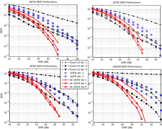
The BER performance of the proposed Bi-SDFE is shown in Fig. 4.2 with BPSK, QPSK, 8PSK and 16QAM modulation schemes with Gray mapping. In each sub-figure, the solid, dotted, and dashed lines denote the performance of the Bi-SDFE, the original SDFE, and the Exact MMSE LE, respectively. Note that the BER curves of the original SDFE of the first iteration are the same as the ones of the Exact MMSE LE because the original SDFE uses the MMSE LE in its first iteration.
Comparing the BER curves of the proposed Bi-SDFE with those of the original SDFE, we can see obvious improvement in all modulation schemes. At the BER level of 10−4, the Bi-SDFE with two iterations gains about 3 dB over the original SDFE with
14 16 18 20 22 24 26 28 10−6 10−5 10−4 10−3 10−2 10−1 BPSK BER Performance SNR (dB) BER 14 16 18 20 22 24 26 28 10−6 10−5 10−4 10−3 10−2 10−1 QPSK BER Performance SNR (dB) 18 20 22 24 26 28 30 32 10−6 10−5 10−4 10−3 10−2 10−1 SNR (dB) BER 8PSK BER Performance 22 24 26 28 30 32 34 36 10−6 10−5 10−4 10−3 10−2 10−1
16QAM BER Performance
SNR (dB) Exact LE iter. 1 Exact LE iter. 2 Exact LE iter. 4 SDFE iter. 2 SDFE iter. 4 Bi−SDFE iter.1 Bi−SDFE iter.2 Bi−SDFE iter.4
Figure 4.2. BER performance of different Turbo equalizers for a 2×2 MIMO system over a five-tap ISI channel.
four iterations for BSPK, QPSK, and 8PSK, while with 16QAM modulation, the perfor-mance gain is 4 dB. Since two SDFEs are used in parallel, the Bi-SDFE requires roughly twice as many computational operations per iteration as the original SDFE. Hence the computational load of the Bi-SDFE with two iterations is approximately the same as that of the original SDFE with four iterations. Considering the saved computation in decoding of the Bi-SDFE scheme, it is safe to say that the Bi-SDFE achieves significant performance improvement over the original SDFE without increasing complexity.
We also observe that, in the medium-to-high SNR region, the first iteration Bi-SDFE outperforms the original SDFE with multiple iterations. This performance enhancement is brought by the bidirectional decision feedback structure and the ex-trinsic information combining, which effectively lower the error propagation compared
with the original SDFE.
Comparing the performance of the proposed Bi-SDFE with the Exact MMSE LE, we see that the Bi-SDFE exhibits a lower SNR threshold than the Exact MMSE LE for all modulation schemes. For 8PSK and 16QAM modulation, the Bi-SDFEs also approaches the performance of the Exact MMSE LEs in the low SNR region. At the BER level of 10−4, after four iterations, the Bi-SDFE outperforms the Exact MMSE LE by 3.5 dB, 1 dB, 2.5 dB and 3 dB with BPSK, QPSK, 8PSK and 16QAM modulation, respectively. The complexity of the Exact MMSE LE is a quadratic function of the filter length, while the complexity of the Bi-SDFE is a linear function of the number of filter coefficients. We conclude that the Bi-SDFE achieves a good trade-off between performance and complexity. Moreover, the Bi-SDFE converges faster than both the original SDFE and the Exact MMSE LE.
It is also interesting to note the performance difference between the original SDFE and the Exact MMSE LE in Fig. 4.2, where the Exact MMSE LE outperforms the original SDFE in all modulation schemes in the low-to-medium SNR region, although the original SDFE performs better than the Low complexity MMSE LE in the medium-to-high SNR regions for MIMO systems [14]. It is this performance gap that motivated the development of the proposed Bi-SDFE.
5 CONVERGENCE ANALYSIS
Turbo equalization is a highly nonlinear dynamic process which makes mathe-matical analysis difficult. However, the numerical tool of the EXIT chart [26] provides good insight of the convergence properties of the turbo process. EXIT charts visualize the exchange of mutual information between the equalizer and the decoder by describing the evolution of the average mutual information (MI) between the extrinsic information and the corresponding information (or coded) bits.
Assume the coded bits are equally likely and are denoted by ˜c∈ {±1}. Denoting
L as the LLR output of either the equalizer or decoder corresponding to the coded bit ˜
c, the mutual information between a coded bit and its LLR is given by [26]
IL(˜c) = 1 2 X ˜ c∈±1 Z ∞ −∞ PL(ξ|c˜) log2 2PL(ξ|˜c) PL(ξ|˜c=−1) +PL(ξ|c˜= +1) dξ (25) = 1− Z ∞ −∞ PL(ξ|˜c= +1) log2(1 +e−ξ)dξ
where PL(L|˜c) is the conditional PDF of the extrinsic information. The mutual
infor-mation computed for the output of the turbo equalizer is denoted as IEon for the nth transmit bit stream, and that computed for the output of the soft decoder is denoted
as IDon. The a priori MIs at the input of the equalizer (decoder) are the interleaved
(de-interleaved) IDon (IEon) as
IEin = Π(IDon) (26)
IDin = Π−1(IEon) (27)
for n= 1,· · · , N.
For MIMO systems with N = 2 transmit elements, the EXIT curve is a two
that is used in the BER simulations in Section 4. We use the same filter parameters:
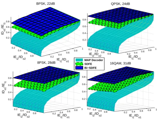
N1 = 9, N2 = 5, N3 = N2 +L− 1 and the rate R = 1/2 convolutional code with generator polynomialG= [7,5]. Figure 5.1 shows the EXIT charts for four modulation schemes at different SNRs, where only the MI transfer curves between the decoder of the first transmit bit stream (n = 1) and the equalizers of the first and second bit streams (n = 1,2) are presented. In all sub-figures, the two dimensional surfaces of the proposed Bi-SDFE are above those of the original SDFE, which indicate faster convergence. 0.2 0.4 0.6 0.8 0.2 0.4 0.6 0.8 1 0.2 0.4 0.6 0.8 IE i1/IDo1 QPSK, 24dB IE i2/IDo2 0.2 0.4 0.6 0.8 0.2 0.4 0.6 0.8 1 0.2 0.4 0.6 0.8 IE i1/IDo1 8PSK, 28dB IE i2/IDo2 ID o 1 /IE i1 0.2 0.4 0.6 0.8 0.2 0.4 0.6 0.8 1 0.2 0.4 0.6 0.8 IE i1/IDo1 16QAM, 31dB IE i2/IDo2 0.2 0.4 0.6 0.8 0.2 0.4 0.6 0.8 1 0.2 0.4 0.6 0.8 IE i1/IDo1 BPSK, 22dB IE i2/IDo2 ID o 1 /IE i1 MAP Decoder SDFE Bi−SDFE
Figure 5.1. Three dimensional EXIT charts for the proposed Bi-SDFE and the original SDFE.
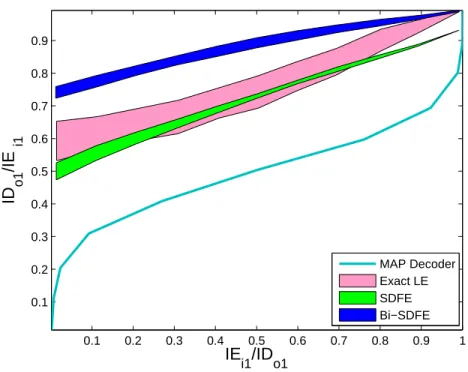
To better visualize the behaviors of the iterative equalizers, we further project the three dimensional EXIT chart for 16QAM modulation into a plane, as shown in Fig 5.2. Note that the lower and upper bounds are calculated by setting the decoder MI of the second transmitter as 0 and 1 respectively. Obviously, the MI gap between the
Bi-SDFE and the MAP decoder is larger than those between the original SDFE and the MAP decoder. As a benchmark, we also plot the MI transfer curves for the Exact MMSE LE in Fig 5.2. The tunnel widths between the transfer curves of the equalizers and the MAP decoder indicate that the Exact MMSE LE converges slightly faster than SDFE, but still slower than the Bi-SDFE, although it achieves almost the same highest mutual information as Bi-SDFE.
0.1 0.2 0.3 0.4 0.5 0.6 0.7 0.8 0.9 1 0.1 0.2 0.3 0.4 0.5 0.6 0.7 0.8 0.9 IE i1/IDo1 ID o1 /IE i1 MAP Decoder Exact LE SDFE Bi−SDFE
6 UNDERSEA EXPERIMENTAL RESULTS
The proposed MIMO Bi-SDFE was also verified by UWA communication data collected in the SPACE08 experiment which was conducted at the coast of Martha’s Vineyard, Edgartown, MA, in October 2008. In this experiment, a MIMO single carrier acoustic communication system with QPSK, 8PSK, and 16QAM modulation was tested. A rate = 1/2 convolutional code with generator polynomial in octal notation G = [17,13] was chosen as the channel code. The center carrier frequency was fc = 13 kHz. The symbol interval was 0.1024 ms, and the roll-off factor for the square-root raised cosine pulse shaping filter was chosen asβ = 0.2. Thus the occupied bandwidth was 11.71875 kHz. Four transducers numbered 0 to 3 were used at the transmitter with Transducer 0 located on a fixed tripod at about 4 m above the ocean bottom. The other 3 transducers were fixed on a vertical array with 50 cm spacing. The top transducer on the vertical array was about 3 m above the ocean bottom. The depth of the experimental water area was about 15 m. Six sets of receive hydrophone arrays were used with a sampling rate of 39.0625 kilo-samples/s. The hydrophone arrays were also fixed with tripods. The top hydrophone of each array was about 3.3 m above the ocean bottom. Experiments were conducted for three transmission ranges: 60 m, 200 m and 1000 m. In this paper, we present the 2×6 MIMO results for 200 m and 1000 m transmissions which recorded 45 packets and 19 packets for the two-transducer systems, respectively.
The format of the transmission packet in the SPACE08 experiment is illustrated in Fig. 6.1, where each packet starts with anm-sequence (maximal-length sequence) [29] of length 511, followed by the data payload of 30 000 symbols with QPSK, 8PSK and 16QAM modulation, respectively.
Considering the harsh UWA channels in the experiment, we partitioned the received signals in the data payload into pilot blocks and overlapped subblocks, as
Data payload Gap m−seq. Gap
511 189 30000 500
block i
Pilot block Pilot block
current block block 2 Info. Info. Info. block 1 previousKpsymbols Kb Kb Kp Kf Kovlp
Figure 6.1. The format of transmission packet in the SPACE08 experiment
depicted in Fig. 6.1. First,Kp pilot symbols were inserted for every Kf symbols, which provided pilot-aided channel estimation. Second, the blocks were partitioned to have
Kovlpoverlapped symbols where the size of each block wasKb. The overlapped symbols at the tail of the previous block were re-equalized in the current block to compensate for SNR degradation. Third, the symbols detected by the current block was utilized for channel re-estimation as a means for decision-directed channel tracking. The size of each block Kb was chosen to guarantee that the time duration of the Kp+Kb symbols was smaller than the channel coherence time. According to the channel scattering function analyzed by the 511-bit m sequence, the channel coherence time was approximately 100 ms. Hence, we set the size of each subblock as Kb = 200, and the number of pilot symbols as Kp = 600. The parameter Kf was adjusted to adapt to the MIMO channels and the modulation levels. The noise variance in each packet was estimated using the received samples during the gap intervals. Typically, the estimated SNR is in the dynamic range from 20 dB to 32 dB.
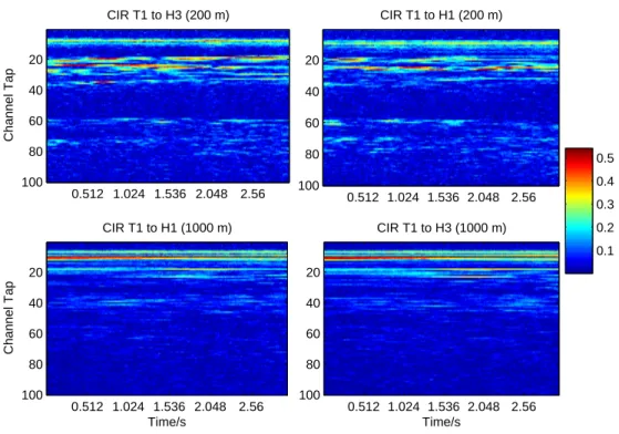
For channel estimation, we adopted the low-complexity normalized least mean squares (NLMS) algorithm to estimate the UWA channels [30]. In Fig. 6.2, we present several typical channels experienced by one data payload transmission, where “T#” and “H#” denote the indexes of the transducer and hydrophone, respectively. The channel impulse responses (CIR) were clearly time-varying, which changed its multipath structure during a transmission block. The channels were also non-minimum phase
systems because the strongest multipath components were not located at the very beginning of the CIR. Interestingly, the 200 m channels experienced more severe ISI than the 1000 m channels, hence channel equalization in the 200 m transmission was more challenging. CIR T1 to H1 (200 m) 0.512 1.024 1.536 2.048 2.56 20 40 60 80 100 Channel Tap CIR T1 to H3 (200 m) 0.512 1.024 1.536 2.048 2.56 20 40 60 80 100 Time/s Channel Tap CIR T1 to H1 (1000 m) 0.512 1.024 1.536 2.048 2.56 20 40 60 80 100 Time/s CIR T1 to H3 (1000 m) 0.512 1.024 1.536 2.048 2.56 20 40 60 80 100 0.1 0.2 0.3 0.4 0.5
Figure 6.2. Examples of channel impulse response over long term observation. Note that the 200 m channels experience more severe multipath ISI than the 1000 m channels.
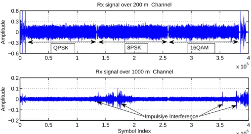
On the other hand, many of the 1000 m packets experienced low signal strength and strong impulsive interference. We plotted two examples of the received signals of the 200 m and 1000 m transmissions, as shown in Fig. 6.3. The received signal in the 200 m channel had clean signals with 0.38 peak-to-peak amplitude, while the 1000 m channel had only 0.038 peak-to-peak amplitude and was corrupted by impulsive interference with large amplitude and duration. Only 19 packets contained usable signals and we processed these 19 packets.
0 0.5 1 1.5 2 2.5 3 3.5 4 x 10⁵ −0.6 −0.3 0 0.3 0.6
Rx signal over 200 m Channel
Amplitude 0 0.5 1 1.5 2 2.5 3 3.5 4 x 10⁵ −0.2 −0.1 0 0.1 0.2 Symbol Index Amplitude
Rx signal over 1000 m Channel 8PSK
QPSK 16QAM
Impulsive Interference
Figure 6.3. Examples of received signals in 200 m and 1000 m transmissions.
The recorded packets were processed by the proposed Bi-SDFE in comparison to the original SDFE. For the Bi-SDFE, the extrinsic LLRs at the output of normal SDFE and time-reversed SDFE are stored into a buffer in each subblock processing. After block-wise processing, we use the collected extrinsic LLRs to estimate the correlation coefficient ˆ̺j,n for LLR combining.
6.1 RESULTS OF 200 M UWA CHANNELS WITH SEVERE ISI
For the 200 m transmission, the UWA channels exhibits fast time-variations and long multipath delays. Therefore, we set the pilot overhead as 12% and 16% for the QPSK and 8PSK data payload, respectively. For the 16QAM data, the overhead was increased to 23% because the transmission source level for all modulation schemes were the same, which made the channel estimation and symbol detection of higher-level modulation systems more difficult.
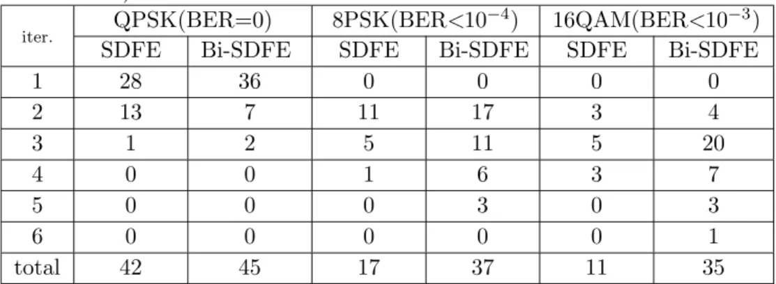
The detection results for each modulation scheme in the 200 m transmission are summarized in Table 6.1. The proposed Bi-SDFE achieved zero BER for all 45 QPSK packets using only three iterations. In contrast, the original SDFE had 42 packets achieving zero BER. With the 3 QPSK packets that experienced tough channels, the
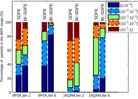
SDFE could not improve the performance with more iterations. For 8PSK packets, the proposed Bi-SDFE achieved BER < 10−4 for 37 packets with 5 iterations, while the original SDFE only had 17 packets achieving BER<10−4. For the 16QAM packets, the Bi-SDFE achieved BER <10−3 for 24 packets in three iterations, and for 35 packets in six iterations. The original SDFE only had 11 packets achieving BER< 10−3. Again, increasing the number of iterations failed to improve the performance of the original SDFE for higher-level modulation schemes.
Table 6.1. Number of packets that achieves the specified BER performance (2×6 MIMO over 200 m channels)
iter. QPSK(BER=0) 8PSK(BER<10
−4) 16QAM(BER<10−3)
SDFE Bi-SDFE SDFE Bi-SDFE SDFE Bi-SDFE
1 28 36 0 0 0 0 2 13 7 11 17 3 4 3 1 2 5 11 5 20 4 0 0 1 6 3 7 5 0 0 0 3 0 3 6 0 0 0 0 0 1 total 42 45 17 37 11 35
The performance comparison between Bi-SDFE and the original SDFE with higher-level modulation is further demonstrated in Fig. 6.4, where the percentages of all the 45 packets in different BER ranges are depicted after two and six iterations. We find that after multiple iterations, the performance gaps between Bi-SDFE and the original SDFE become much larger than the gaps after one iteration. This is the case for both 8PSK and 16QAM packets, which indicates that the bidirectional structure indeed helped to reduce the error floor through multiple iterations. The BER performance improvement was one to two orders of magnitude better than the original SDFE. After 6 iterations, Bi-SDFE successfully detected 95.6% of the 8PSK packets with BER less than 10−3. However, with the original SDFE, there are still 13.3% 8PSK