A University of Sussex DPhil thesis
Available
online
via
Sussex
Research
Online:
http://sro.sussex.ac.uk/
This
thesis
is
protected
by
copyright
which
belongs
to
the
author.
This
thesis
cannot
be
reproduced
or
quoted
extensively
from
without
first
obtaining
permission
in
writing
from
the
Author
The
content
must
not
be
changed
in
any
way
or
sold
commercially
in
any
format
or
medium
without
the
formal
permission
of
the
Author
When
referring
to
this
work,
full
bibliographic
details
including
the
author,
title,
awarding
institution
and
date
of
the
thesis
must
be
given
ADAPTIVE OBJECT SEGMENTATION AND
TRACKING
by
Nagachetan Bangalore Manjunathamurthy
SUBMITTED FOR THE DEGREE OF DOCTOR OF PHILOSOPHY
AT THE UNIVERSITY OF SUSSEX
School of Engineering and Design University of Sussex
Brighton
i
Declaration
I hereby declare that this thesis has not been and will not be, submitted in whole or in part to another University for the award of any other degree.
Signature
Nagachetan Bangalore Manjunathamurthy Dated: 12 January 2012
ii
ADAPTIVE OBJECT SEGMENTATION AND TRACKING
Summary
Efficient tracking of deformable objects moving with variable velocities is an important current research problem. In this thesis a robust tracking model is proposed for the automatic detection, recognition and tracking of target objects which are subject to variable orientations and velocities and are viewed under variable ambient lighting conditions. The tracking model can be applied to efficiently track fast moving vehicles and other objects in various complex scenarios. The tracking model is evaluated on both colour visible band and infra-red band video sequences acquired from the air by the Sussex police helicopter and other collaborators. The observations made validate the improved performance of the model over existing methods.
The thesis is divided in three major sections. The first section details the development of an enhanced active contour for object segmentation. The second section describes an implementation of a global active contour orientation model. The third section describes the tracking model and assesses it performance on the aerial video sequences.
In the first part of the thesis an enhanced active contour snake model using the difference of Gaussian (DoG) filter is reported and discussed in detail. An acquisition method based on the enhanced active contour method developed that can assist the proposed tracking system is tested. The active contour model is further enhanced by the use of a disambiguation framework designed to assist multiple object segmentation which is used to demonstrate that the enhanced active contour model can be used for robust multiple object segmentation and tracking. The active contour model developed not only facilitates the efficient update of the tracking filter but also decreases the latency involved in tracking targets in real-time. As far as computational effort is concerned, the active contour model presented improves the computational cost by 85% compared to existing active contour models.
The second part of the thesis introduces the global active contour orientation (GACO) technique for statistical measurement of contoured object orientation. It is an overall object orientation measurement method which uses the proposed active contour model along with statistical measurement techniques. The use of the GACO technique, incorporating the active contour model, to measure object orientation angle is discussed in detail. A real-time door surveillance application based on the GACO technique is developed and evaluated on the i-LIDS door surveillance dataset provided by the UK Home Office. The performance results demonstrate the use of GACO to evaluate the door surveillance dataset gives a success rate of 92%.
Finally, a combined approach involving the proposed active contour model and an optimal trade-off maximum average correlation height (OT-MACH) filter for tracking is presented. The implementation of methods for controlling the area of support of the OT-MACH filter is discussed in detail. The proposed active contour method as the area of support for the OT-MACH filter is shown to significantly improve the performance of the OT-MACH filter‟s ability to track vehicles moving within highly cluttered visible and infra-red band video sequences.
iii
Acknowledgements
With the deepest gratitude I wish to thank every person who has come into my life and inspired, touched and illuminated me through their presence. I would like to express my gratitude to all who consciously or unconsciously have made contributions to my research pursuit. I would like to start with special thanks to my main supervisor, Dr. Rupert Young. Rupert is an embodiment of an affable and charming personality. He bears a deep sense of understanding and knowledge in optics and computer vision methods. It is due to the thought provoking discussions with him over a wide range of topics, I have realised that a deep and thorough understanding of a problem helps in arriving at a solution in an efficient way. I thank him for generously sharing his wisdom and for the kind cooperation that he bestowed upon me in all matters for the asking. The way he greets me with a pleasant smile on his face is greatly alleviating and dispels any hesitation on my part for approaching him with any problem. I owe a deep sense of gratitude for his keen support, patience and guidance without which my research wouldn‟t have been possible.
I would also like to take this opportunity to acknowledge my gratitude to my co-supervisor, Prof. Chris Chatwin. Chris is the director of our research group and has an exuberant experience in research on various fields with numerous publications to his credit. I thank him for providing me various opportunities to work on real-time projects that gave me a broader sense of understanding and approach in solving several practical research problems. I am pleased to have had the honour of working under him and receive valuable advice and directions regarding strategies to be adopted in facing challenging research problems. I owe a deep sense of gratitude to him for making my research work truly productive and stimulating.
I would like to thank Dr. Philip Birch, for all his support and advice that helped me gain a deeper understanding on practical research issues which improved my programming skills. He helped me learn a great deal of skills involved in innovating research into a practical cutting edge solutions for various real-time applications. I am thankful to the wonderful administration and support staff at the School office. Thanks also goes to my research colleagues and students with whom I have spent a wonderful time at Sussex. Finally, I would like to thank my family and friends for their support and for always standing by me during the ups and downs of my life. I am very grateful to the supreme light that drove and drives me in all walks of my life for making my research a plain sail.
Nagachetan Bangalore Manjunathamurthy University of Sussex
iv
List of Acronyms
AC Active contours
ACE Average correlation energy
ACH Average correlation height
AWGN Additive white Gaussian noise
ATR Automatic target recognition
ASM Average similarity measure
CM Computational model
DoG Difference of Gaussian filter
DS Door surveillance system
DSTL Defence science and technology laboratory
EACS Enhanced active contour snakes
EKF Extended Kalman filter
FFT Fast Fourier transforms
FFTW Fastest Fourier transform in the West
GACO Global active contour orientation
GHT Generalised Hough transforms
v
IFFT Inverse fast Fourier transforms
i-LIDS Imagery library for intelligent detection systems
LoG Laplacian of a Gaussian filter
MACE Minimum average correlation energy filter
MACH Maximum average correlation height filter
MVSDF Minimum variance synthetic discriminant function
MoG Mixture of Gaussian
OT-MACH Optimal trade-off maximum correlation height filter
ONV Output noise variance
PF Particle filter
SDF Synthetic discriminant function
SIFT Scale invariant feature transform
SURF Speeded up robust features
vi
List of Symbols
α Coefficient of power spectral density of additive input noise β Coefficient of average power spectral density of training images γ Coefficient of similarity matrix of the training images
σ Standard deviation
Logical condition „for each‟
ϵ Notation for signifying „belongs to‟
a Active contour snake parameter emphasising the continuity energy
b Active contour snake parameter emphasising the curvature energy
c Active contour snake parameter emphasising the image energy
N Total number of snaxels in the contour vector
F-1(x), F(x) Fourier transform and inverse Fourier transform θc Global active contour orientation angle
θi(x, y) Orientation angle at each contour point in a contour vector RHarris Harris response function
Sx Similarity matrix of the training image set
vii
Table of Contents
DECLARATION ... I SUMMARY ... II ACKNOWLEDGEMENTS ... III LIST OF ACRONYMS ... IV LIST OF SYMBOLS ... VI LIST OF FIGURES ... XI LIST OF TABLES ... XVII LIST OF PUBLICATIONS ... XVIIIINTRODUCTION ... 1
1.1 MOTIVATION ... 1
1.2 DEFORMABLE TEMPLATES ... 3
1.3 ACTIVE CONTOURS (SNAKES) ... 4
1.4 CORRELATION PATTERN RECOGNITION ... 9
1.5 A BRIEF OVERVIEW OF THE THESIS CHAPTERS ... 14
ENHANCED ACTIVE CONTOUR SNAKES INCORPORATING A DIFFERENCE OF A GAUSSIAN FILTER ... 17
2.1 INTRODUCTION ... 17
2.2 CHAPTER ORGANISATION ... 19
2.3 DESIGN OF THE DIFFERENCE OF GAUSSIAN FILTER ... 19
2.4 ENHANCED ACTIVE CONTOUR EXPRESSION USING THE DOG FILTER ENERGY TERM ... 23
viii
2.5 AUTOMATIC INITIAL CONTOUR EXTRACTION ... 27
2.6 SNAKE DEFORMATION, PROGRESSION AND ALGORITHM DESIGN FLOWCHART ... 34
2.6.1 Snake deformation ... 34
2.6.2 Snake progression ... 34
2.6.3 Overall design flowchart of the enhanced active contour framework ... 36
2.7 RESULTS AND DISCUSSION ... 38
2.8 SUMMARY ... 42
ENHANCED ACTIVE CONTOUR SNAKES FOR MULTIPLE OBJECT TRACKING AND ITS APPLICATIONS ... 45
3.1 INTRODUCTION ... 45
3.2 CHAPTER ORGANISATION ... 46
3.3 MULTIPLE OBJECT CONTOURING ... 46
3.3.1 Contour termination ... 47
3.3.2 Contour splitting step ... 47
3.3.3 Contour selection step ... 50
3.4 STATISTICAL MEASURES OF THE ENHANCED ACTIVE CONTOUR SNAKES (EACS)... ... 54
3.4.1 Active contour bounding rectangle ... 54
3.4.2 Active contour centroid ... 57
3.5 UPPER BODY HUMANOID SKELETAL MODELLING APPLICATION ... 58
3.6 SUMMARY ... 64
GLOBAL ACTIVE CONTOUR ORIENTATION AND ITS APPLICATIONS ... 65
4.1 INTRODUCTION ... 65
ix
4.3 GLOBAL ACTIVE CONTOUR ORIENTATION MEASUREMENT ... 67
4.4 GLOBAL ACTIVE CONTOUR ORIENTATION DESIGN FLOWCHART ... 69
4.5 REAL-TIME DOOR SURVEILLANCE APPLICATION ... 72
4.5.1 Door surveillance introduction ... 72
4.5.2 Edge-map based Harris corner detector ... 74
4.5.3 Door surveillance algorithm design ... 78
4.5.4 Hough transform based error correction ... 80
4.6 RESULTS AND DISCUSSION ... 82
4.7 SUMMARY ... 90
ENHANCED ACTIVE CONTOUR ASSISTED OT-MACH FILTER TRACKER ... 92
5.1 INTRODUCTION ... 92
5.2 CHAPTER ORGANISATION ... 93
5.3 DESIGN OF OPTIMAL TRADE-OFF (OT)MACH FILTER ... 94
5.4 INTERRUPT BASED USER INTERFACE ... 95
5.5 REFERENCE IMAGE EXTRACTION ... 96
5.5.1 Rectangular target extraction ... 96
5.5.2 Circular target extraction ... 99
5.5.3 Active contour based target extraction ... 100
5.6 COMPUTING ROTATIONALLY MULTIPLEXED REFERENCE IMAGE ... 104
5.7 REAL-TIME IMPLEMENTATION OF THE OT-MACH FILTER ... 105
5.8 COMPARISON OF OT-MACH TRACKER WITH KALMAN AND PARTICLE FILTERS ... ... 110
5.9 USE OF AN EXTENDED KALMAN FILTER TO DISTINGUISH BETWEEN TARGET AND NON-TARGET OBJECTS WHEN IN CLOSE PROXIMITY ... 112
x
5.10 REPRESENTATIVE EXAMPLES OF TRACKING RESULTS ... 114
5.11 SUMMARY ... 127
CONCLUSIONS AND FUTURE WORK ... 128
6.1 CONCLUSIONS ... 128
6.2 FUTURE WORK ... 132
APPENDIX 1 ... 135
xi
List of figures
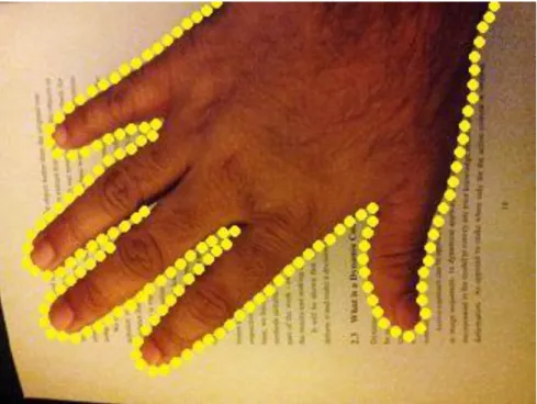
1.1 Active contour snake contouring the shape of the hand in the image (drawn in
yellow)---8
1.2 An example tank training dataset (angle of rotation between 0 and 180 degrees)-13 1.3 Correlation plot for an in-class target image correlated with an OT-MACH filter function---14
2.1 Gaussian filter function mesh plot, with σ = 92 pixels with a mesh size of 512 x 512 pixels---21
2.2 DoG filter shown as a band-pass filter in the spatial frequency domain---22
2.3 Test frame from a colour video---23
2.4 DoG band-pass filtered image with an appropriate bias added for display---24
2.5 Frame 1 of a colour video to be DoG filtered---28
2.6 Frame 2 of the colour video to be DoG filtered---28
2.7 DoG filtered frame 1 with an appropriate bias added for display---29
2.8 DoG filtered frame 2 with an appropriate bias added for display---30
2.9 Resultant image after performing absolute subtraction of the thresholded DoG filtered images---31
2.10Boundary traced resultant image (boundary drawn in green for display)---32
2.11Initial reduced contour vector of snaxels plotted as blue dots for display---33
2.12Snake deformation onto moving object at Frame 3 in a video sequence---35
2.13Snake progression on moving object at Frame 30 in a video sequence---35
2.14Flowchart of the enhanced active contour snake (EACS) framework---36
2.15Frame 1 of the colour video sequence (before deformation)---38
xii
2.17Frame 60 of the video sequence after deformation and progression---39 2.18Frame 103 of the colour video sequence continuously tracked even after the object
scale changes---39 2.19Enhanced active contour snake on infrared video at the 10th frame showing the snake deformation on target---40 2.20Enhanced active contour on target in infrared video sequence, depicting continuous tracking and progression in the 22nd frame---41 3.1 Contour „v’ analysed for segments before splitting---47 3.2 Identified contour segments to be divided are highlighted---48 3.3 The segments identified that need splitting; two new points are appended to create
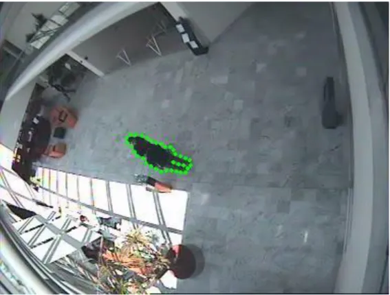
three new segments---48 3.4 New set of segments reorganised to form three separate active contours---49 3.5 Contour vector locked onto the human holding a box (drawn in green, signifying the original contour vector considered for subsequent splitting)---50 3.6 Two distinct contour vectors created from the single contour present in previous frames as shown in Figure 3.5---51 3.7 Single contour vector drawn in green covering two people occluding each other in
a scene---52 3.8 Two distinct contour vectors created from the single contour present in the
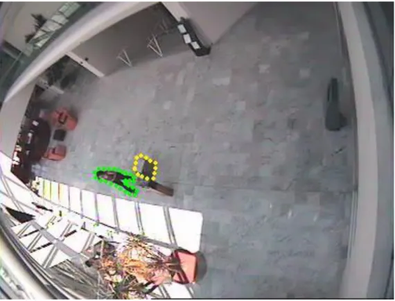
previous frames as shown in Figure 3.7---53 3.9 The active contour vector plotted on the object being contoured---55 3.10The minimum bounding rectangle bounding the contour vector---56 3.11Active contour centroid point plotted in green surrounded by a yellow circle for
display---57 3.12The EACS contour vector drawn in yellow for the humanoid being contoured--58
xiii
3.13Active contour centroid point computed from the EACS contour, plotted in green surrounded by a yellow circle for display---59 3.14The upper body skeletal stick drawn between the centroid and the top most point of the head determined using equation 3.13---60 3.15The centre of the neck point deduced using the Euclidian distance between the centroid and the top of the head in the humanoid being contoured---61 3.16The upper body humanoid skeletal stick model derived from the active contour centroid and AC bounding rectangle parameters---62 4.1 Global active contour of the object contoured in blue with AC vector (3450)---69 4.2 Overall flowchart for computing the global active contour orientation (GACO)--70 4.3 Global active contour of the object contoured in blue with AC vector computed as
1620---71 4.4 The single door video frame from i-LIDS door surveillance dataset to be
processed---74 4.5 (a) Left: The top-left corner of the door frame converted to greyscale intensity
image; (b) Right: the edge detector used on the left image to find Omni-directional edges for further processing.---74 4.6 The single door video frame with Harris corner detector applied to the Harris
window showing the displaced corner at the top when the door opens---76 4.7 The double door video frame with the displaced corner at the top---77 4.8 The Door surveillance system designed to evaluate the i-LIDS door surveillance
dataset---78 4.9 Hough transform region and the line detected for Single door i-LIDS video---80 4.10Hough transform region and the line detected for the double door i-LIDS video-81 4.11Active surveillance on single door videos HW on top-left corner---82
xiv
4.12Primary alarm on single door videos with 2 corners detected in HW---82
4.13Secondary alarm on single door videos showing „exit‟ at the SW---82
4.14Robust surveillance during SW occlusion due to external activity (no false alarm) 4.15Active surveillance on double door videos HW at top-centre---83
4.16Primary alarm on double door videos with 2 corners displaced in the HW---84
4.17Secondary alarm on double door videos when 2 corners move in the HW---84
4.18Robust surveillance at the double door during occlusions in the SW---85
4.19Primary alarm as the double door displaces in poor quality frame---87
4.20Secondary alarm signifying an exit at the door after Hough transform error correction---87
5.1 Initialisation circle over the target vehicle to be tracked---95
5.2 Target reference image used to train the filter---96
5.3 Flowchart for rectangular target extraction (A)---97
5.4 Circular target extraction (B)---98
5.5 Initialisation by selecting circular area around the target---100
5.6 The reference image generated for training the filter---101
5.7 Active contour extraction method---101
5.8 Rotationally multiplexed reference image---103
5.9 Cross-hair on target---104
5.10Correlation plane with peak location at (X, Y) = (195,342)---105
5.11The OT-MACH tracker---106
5.12FFT Shift operation---107
5.13OT-MACH filter module---108
5.14Correlation and decision module---108
xv
5.16Particle filter (blue, green and red) and OT-MACH filter tracker (Yellow)---110
5.17Kalman filter and OT-MACH tracker outputs (frame 104)---112
5.18Kalman filter and OT-MACH tracker outputs (frame 122)---112
5.19DSTL Video (1) frame 10 target acquired---113
5.20DSTL Video (1) continuous tracking at frame 30---113
5.21DSTL Video (2) frame 100 target acquired---114
5.22DSTL Video (2) continuous tracking, scale and orientation changed at frame 130---115
5.23Sussex Police video (1) Frame 5 target acquired in the presence of false objects ---116
5.24Sussex Police video (1) Frame 15 with multiple false objects---116
5.25Sussex Police video (1) Frame 100, dynamic scale changes---117
5.26Sussex Police video (1) Frame 120, scale changed false object present in close proximity---118
5.27Sussex Police video (1) Frame 240, scale changed---118
5.28Sussex Police video (1) scale changed and noisy frame at Frame 250---119
5.29Sussex Police video (2) Frame 50, scale changed---120
5.30Sussex Police video (2) Frame 65, scale changed, varying lighting conditions--120
5.31Sussex Police infra-red video frame 65, scale changed---121
5.32Sussex Police infra-red video frame 104, scale changed with Gaussian noise----121
5.33Sussex Police infra-red video frame 265, dynamic scale change---122
5.34Sussex Police infra-red video frame 435, dynamic scale and orientation changes ---122
5.35Sussex Police video (3) frame 35 with a difficult coloured car being track---123
xvi
5.37Noisy DSTL video (3) frame 15, scale and orientation changed---125 5.38Noisy DSTL video (3) frame 75, continuous tracking during scale and orientation
xvii
List of Tables
2.1 Energy terms of the snake listed and described---33 4.1 Overall performance of the proposed door surveillance application using the GACO secondary alarm approach---88 6.1 OT-MACH filter tracker ideal parameters and changes required for different scenarios---132
xviii
List of Publications
1. Philip Birch, Bhargav Mitra, Nagachetan Bangalore, Saad Rehman, Rupert Young, Chris Chatwin, “Approximate bandpass and frequency response models of the difference of Gaussian filter”, Optics Communications, vol. 283, no. 24, pp. 4942-4948, December 2010.
2. Nagachetan Bangalore, Rupert Young, Philip Birch, Chris Chatwin, “Tracking moving objects using bandpass filter enhanced localisation and automatic initialisation of active contour snakes”, ICGST International Journal of Graphics, Vision and Image Processing GVIP, Vol. 10, no. 4, pp. 1-8, October 2010.
3. Nagachetan Bangalore, Waqas Hassan, Bhargav Mitra, Philip Birch, Rupert Young, Chris Chatwin, “Door surveillance using edge map-based Harris corner detector and active contour orientation”, in Proc. of Visual Information processing XX, SPIE Defense, Security + Sensing, vol. 8056, Orlando, Florida, USA, April 2011, pp. 805608-1:10.
4. Waqas Hassan, Nagachetan Bangalore, Philip Birch, Rupert Young, Chris Chatwin, “Object Tracking in a Multi Camera Environment,” in Proc. of IEEE International Conference on Signal and Image Processing Applications (ICSIPA
2011), Kuala Lumpur, November 2011.
5. Ahmad Alkandri, Akber Gardezi, Nagachetan Bangalore, Philip Birch, Rupert Young, Chris Chatwin, “Automatic parameter adjustment of difference of Gaussian (DoG) filter to improve OT-MACH filter performance for target recognition applications”, in Proc. of Electro-Optical and Infrared Systems: Technology and Applications VIII, SPIE Europe Security+Defense, vol. 8185, Prague, Czech Republic, September 2011, pp. 81850M-1:10.
6. Waqas Hassan, Nagachetan Bangalore, Bhargav Mitra, Philip Birch, Rupert Young, Chris Chatwin, “Robust human intrusion detection technique using hue-saturation histograms”, in Proc. of Optical Pattern Recognition XXII, SPIE
xix
Defense, Security + Sensing, vol. 8055, Orlando, Florida, USA, April 2011, pp. 80550J-1:12.
7. Bhargav Mitra, Waqas Hassan, Nagachetan Bangalore, Philip Birch, Rupert Young, Chris Chatwin, “Tracking illegally parked vehicles using correlation of multi-scale difference of Gaussian filtered patches”, in Proc. of Optical Pattern Recognition XXII, SPIE Defense, Security+Sensing, vol. 8055, Orlando, Florida, USA, April 2011, pp. 805503-1:9.
8. Bhargav Mitra, Nagachetan Bangalore, Waqas Hassan, Philip Birch, Rupert Young, Chris Chatwin, “Change of illumination tolerant scene surveillance using a multi-stage edge detector”, Asian Journal of Physics, Vol 19, No. 1, pp. 87-97, 2010.
9. Akber Gardezi, Nagachetan Bangalore, Ahmad Alkandri, Philip Birch, Rupert Young, Chris Chatwin, “Application of speed-enhanced spatial domain correlation filters for real-time security monitoring”, in Proc. of Optics and Photonics for Counterterrorism and Crime Fighting VII, SPIE Europe Security+Defense, vol. 8189, Prague, Czech Republic, September 2011, pp. 81890R-1:12.
10.Waqas Hassan, Bhargav Mitra, Nagachetan Bangalore, Philip Birch, Rupert Young, Chris Chatwin, “Image processing methods for event detection from video surveillance sequences”, Information Technologies, System and Networks
(ITSN-2010), Moldova, May 2010.
11.Philip Birch, Waqas Hassan, Nagachetan Bangalore, Rupert Young, Chris Chatwin, “Stationary Traffic Monitor,” 4th International Conference on Imaging for Crime Detection and Prevention (ICDP-11), London, November 2011.
12.Chris Chatwin, Rupert Young, Philip Birch, Waqas Hassan, Bhargav Mitra, Nagachetan Bangalore, Ioannis Kypraios, “Global Panopticon”, IET, Invited Presentation, The Hawth-Spotlight, Crawley, Sussex, 8th October, 2009.
xx Technical Reports
1. Nagachetan Bangalore, Bhargav Mitra, Philip Birch, Rupert Young, Chris Chatwin, “Filter Design, Target Reference & Clutter Models for Recognition and Prioritisation”, Report 1, Centre for Defence Enterprise -
TR1/US/C4ISTAR/RT/COM/7/101/100301CCRYPB, 1st March 2010.
2. Nagachetan Bangalore, Bhargav Mitra, Philip Birch, Rupert Young, Chris Chatwin, “Design of Optimal trade-off (OT) MACH filter”, Report 2, Centre for
Defence Enterprise – TR2/US/C4ISTAR/RT/COM/7/101/100301CCRYPB, 10th
May 2010.
3. Nagachetan Bangalore, Bhargav Mitra, Philip Birch, Rupert Young, Chris Chatwin, “Tracking of motor vehicles from the Sussex police helicopter colour camera using the OT-MACH correlation filter”, Report 3A, Centre for Defence
Enterprise – TR3A/US/C4ISTAR/RT/COM/7/101/100301CCRYPB, 5th July
2010.
4. Nagachetan Bangalore, Bhargav Mitra, Philip Birch, Rupert Young, Chris Chatwin, “Tracking of vehicles from the Sussex police helicopter colour camera using the OT-MACH correlation filter II”, Report 4A, Centre for Defence
Enterprise – TR4A/US/C4ISTAR/RT/COM/7/101/100301CCRYPB, 25th
September 2010.
5. Nagachetan Bangalore, Bhargav Mitra, Philip Birch, Rupert Young, Chris Chatwin, “Reducing the Operational Burden On Imagery Analysts -Target Detection, Recognition, Identification and Prioritisation - Sussex”, Report Final,
Centre for Defence Enterprise –
1
Chapter 1
INTRODUCTION
1.1Motivation
Image is an information carrier according to a computer vision scientist [1], [2]. The information contained in an image may not always be perceivable with the human eye. The information may be corrupted by noise or simply be combined with information that is of no interest creating a confusion. The first and most important step in image processing or analysis involves segmentation of the objects in an image. Segmentation divides an image into its constituent parts. Segmentation algorithms are generally based on discontinuities and similarities in an image. It is often difficult to identify and classify similarities such as edges, especially if they are spurious. Hence, high level segmentation methods involve techniques utilising a priori knowledge about the object‟s shape, texture, colour or position which are included in the search procedures. Object tracking involves the detection of moving objects over multiple frames captured from a video source. The objects must be associated with the same object observed or segmented in the previous frames in order to successfully track an object. With the tracking information of an object it is possible to ascertain a great deal of information regarding the nature of the object that is considered for tracking. The task of tracking an object becomes particularly challenging when there are multiple moving objects involved, when the objects are moving at high velocities or when the camera is constantly in motion making the whole scene dynamic.
The tracking process can be divided into the processes of target representation, localisation, filtering and association. The target representation and localisation process
2
attempts to recognise objects in the scene and represent them in a simplified way. Blob detection is one the common methods for achieving this, where the regions of the image are segmented from the background using a known characteristic of the object such as its relative speed, its intensity or colour. Moving regions can be extracted using a number of methods such as optical flow [14], [6], which continually updates the velocity vectors across the image. Multiple cameras can be used to acquire the position and movement information in three dimensions. The use of multiple cameras is by far the most robust method to extract moving objects in three dimensions but it is not practical for most applications. The most common method for extracting moving regions from a single static camera is by using the background subtraction method to distinguish between the area of movement and the areas of the background.
Objects can also be represented by the shape of their boundaries and can be tracked across consecutive frames using active contour methods [2], [3], [11], [18]. Active contour methods attempt to identify the target boundary points using random and active contour segmentation and hence allow tracking between frames. These methods are useful in tracking deformable dynamic objects based on several image characteristics such as intensity, colour or edges [48], [32], [29], [28], [26] and can therefore track objects in moving backgrounds thus making them suitable for most real-time object segmentation and tracking scenarios. Chapter 2 of the thesis discusses an adaptive segmentation and tracking technique using the enhanced active contour snake (EACS).
When a particular type of target is to be tracked in a scene containing similar moving objects, it is often necessary to use correlation pattern recognition methods, such as maximum average correlation height (MACH) filters [75], [67], [77], [98], to classify, locate and track the objects in the scene. This can be used in conjunction with enhanced active contour techniques to reduce the computational cost involved in the training of
3
the correlation filters for pattern recognition and tracking purposes. An adaptive area of support based on the enhanced active contour method, together with the optimal trade-off maximum average correlation height (OT-MACH) filter, can be used for robust object segmentation and tracking in challenging scenarios. This method is described and demonstrated in Chapter 5 of the thesis.
1.2Deformable templates
Deformable templates are an important approach for object estimation for segmentation and tracking. The theory of deformable templates can be related to the shape class description based on pattern theory [32], [29], [24], [12], [10], [8].
Deformable templates utilise prior knowledge of the shape of the object specified in the form of a sketch, binary template or parametric prototype. The a priori knowledge is encoded either in the form of the edge information computed from the binary template or the parameter vector. The difference between snakes and deformable templates is that snakes are form-free energy minimising functions [3], [13], [15], [17], [20]. In snake models, there is no global structure of the curves except for the general regularisation constraints such as continuity and smoothness of the boundary to be contoured. The parametric deformable templates control deformations using a pre-defined set of parameters capable of encoding a specific shape to initiate deformation. Hence, the deformable templates are used when more specific shape information is available than can be described either by a binary template or a set of parameters [35], [32], [27].
The prototype template describes the most prominent instance of the object boundary defining the shape of the object to be contoured. A parametric transformation is applied to the prototype to deform its boundaries varying the deformation parameters in order to capture a large variety of possible instances of the object. Several variations may be
4
captured by making random deformations to the prototype so that the deformed template matches the object of interest. However, the object of interest may be noise corrupted or degraded causing the original shape to be lost. In such a circumstance, a deformed template may match the object better than the original prototype defined.
By using an appropriate edge detector [14], [64], [46], the object boundaries can be extracted from the image. The deformable templates can be matched for all objects found using the template base. A potential energy function can be used to check for similar objects by aligning the templates from the database with the image being used.
The detection can be simplified and improved by imposing a probability distribution on the images in the database. It is assumed that the prototype template defined is the most likely a priori shape of the object. One of the earliest approaches to deformable template analysis was aimed at finding facial features for human recognition purposes [8], [7], [17], [62]. The deformable template techniques depend on a number of parameters which is cumbersome for optimisation purposes. Thus an alternative is to investigate techniques that use fewer parameters. Snakes are a more popular approach, that evolve a set of points (a contour) to match the object in the image data rather than evolving a set of shapes to match the object [24] [29].
1.3Active contours (Snakes)
Active contours or Snakes are a completely distinct approach to feature extraction [3]. The active contour is featured as a set of points enclosing a target feature to be extracted. It can be visualised like a balloon that is placed outside the object, enclosing it to find the shape of the object in an image [2]. Similarly, the active contours arrange a set of points in a way to describe the shape of the target object. Active contour snakes
5
were originally designed for interactive extraction of the object shape, though they are now usually deployed for automatic feature extraction [6], [11], [5], [29].
Active contours are described as an energy minimisation process. The target object feature is a minimum of a suitably formulated and balanced energy functional. The energy functional includes more information than just the edge information of the object under consideration. The energy functional includes properties that control the snake or contour‟s progression.
A snake represents a compromise between its own properties, known as intrinsic properties, and the image properties, also known as extrinsic properties. Based on this the active contour snake energy functional is the addition of a function of the contour‟s internal energy, constraint energy and the image energy. These are denoted as Eint, Eimage
and Econ, respectively. The energy terms are the function of the set of points that make
up the snake, represented as v(s) which is a set of the x and y co-ordinates of the points in the snake.
The energy functional is defined as the integral of all the energy functional of the snake, given that s is a member of the set [0,1] is the normalised length around the snake. The energy functional of the snake Esnake is given by equation 1.1:
v
s
E
v
s
E
v
s
ds
E
E
s con image snake
1 0 int (1.1)where the internal energy Eint controls the natural behaviour of the snake and the arrangement of the snake points in a contour and the image energy Eimage controls the emphasis of the snake in choosing low-level features of the image such as the edges of the object [25], [32], [2]. The constraint energy allows the higher level information to control the snake evolution. The criterion used to make the active contour evolve is to
6
minimise the energy in equation 1.1 for each point in the contour. A set of new contour points are chosen with lower energy that is a better match to the target object shape based on the values of the energy terms around it. The active contours seek a set if points v(s) to choose a lower energy than the original set of points. This can be expressed mathematically as in equation 1.2:
0
dv
dE
snake(1.2)
The energy functional is expressed in terms of functions of the snake and the image in which the object is contoured. These functions form the snake energy according to the values chosen for the weighting coefficients. The internal energy of the snake is defined to be a weighted sum of first order and second order derivatives of the contour v(s) [10] [3]. This can be expressed as shown in equation 1.3:
2
2
2 2 intds
s
v
d
s
b
ds
s
dv
s
a
E
(1.3)The first order differential measures the energy due to stretching, also referred to as elastic energy of the snake. A higher value of this differential implies a high rate of change in the region of the contour. The second order differential measures the energy due to bending, also known as the curvature energy. The first order differential is weighted by a(s) controlling the rate of the contribution of the elastic energy due to point spacing in the contour. The second order differential is weighted by b(s)
controlling the rate of contribution of the curvature energy due to point variation. The parameters a and b control the shape of the snake that is needed to contour an object. Low values of a imply that the points can change in spacing flexibly, whereas higher values imply that the snake is formed by evenly spaced contour points which are known
7
as snaxels. Lower values of b imply that the curvature is minimised and the contour can form corners in its length, whereas higher values of b imply that the contours are smooth. The image energy attracts the contour to low-level features such as brightness or edge data. For instance, the edges and intensity values in the image can be used to contribute to the energy functional. Each of these energies can be controlled by weighting factors. The image energy function can be expressed as in equation 1.4:
gradient gradient ensity Intensity image
W
E
W
E
E
.
int
.
(1.4)where the intensity based energy is denoted as Eintensity and the corresponding weighting
parameter is denoted as Wintensity. The energy based on the gradient value is represented
as Egradient and the corresponding weighting coefficient controlling the emphasis of the
gradient energy is denoted as Wgradient. Several combinations of low-level features can
be emphasised and extracted using them as the image energy in the snake energy equation [31], [32], [35]. The work in the thesis discusses the use of the difference of Gaussian (DoG) filtered image term in the energy equation so emphasising the negative polarity around the zero-crossing edge detected by the application of this band pass filter to the image. Figure 1.1 illustrates an active contour snake deformed on to a hand image; note that the contour is an open contour, meaning that the first snaxel and the last snaxel of the contour are not connected to each other to form a closed contour.
8
Figure 1.1: Active contour snake contouring the shape of the hand in the image (drawn in yellow)
The active contours can be finite element based or finite difference based. The most common and easier way of realising the active contours was proposed by Shah et al
[19], [16], [25]. It is known as the Greedy algorithm for snakes. It implements the energy minimisation process purely as a discrete algorithm. The greedy process starts by a user defined specification of an initial contour. More recent work suggests several automatic methods of specifying an initial contour of the snake [3], [8], [27]. The greedy algorithm evolves the snake in an iteration based local neighbourhood scan for the lowest energy snaxel points. The new set of points are those neighbourhood points which have the overall lowest energy points computed for each snaxel based on the energy minimisation expression for the snake. The technique is called „greedy‟ by virtue of the fact that the search propagates over the contour for each snaxel around its local neighbourhood [21]. The enhanced active contour snake technique discussed and designed in this thesis uses the greedy search technique for the energy computations.
9
More detailed discussion of the enhanced active contour snakes (EACS) is given in Chapter 2 of this thesis.
1.4Correlation pattern recognition
Correlation pattern matching or recognition provides a mechanism for comparing two image signals. It has the benefit of being shift invariant so it can also provide tracking, if implemented via the Fourier domain, at no extra computational cost. If f(.) and g(.) are two continuous functions, the correlation between the two signals c(x) is given by:
x
f
x
g
x
c
* (1.5)Equation 1.5 is in fact the integral equation shown in equation 1.6;
f
g
x
d
x
c
* (1.6)where is a dummy variable. The function c(x) gives a measure of the similarity of the function f(.) and the function g(.) at position x. The function f (.) is now referred to as the input signal and the function g(.) as the target signal [76], [77]. However, when dealing with discrete digitised images, it is more common to modify the integral equation 1.6 so that it is expressed as a discrete summation, as shown in equation 1.7:
k l n l m k l k n mf
g
c
, , , (1.7)where m and n are valid 2-D pixel co-ordinates. For larger images this can be rather computationally expensive so it is common to use the Fourier transform relationship which can be expressed as in equation 1.8:
m
n
F
F
f
m
n
F
g
m
n
10
where the F(.) indicates a Fourier transform operation and F-1(.) denotes the inverse
Fourier transform of the function contained in the brackets. In a discrete image, equation 1.7 is therefore replaced by two forward fast Fourier transforms (FFTs) and a complex multiply of the conjugate Fourier spectrum of the target function with the Fourier spectrum of the input signal function, the result of which is then inverse fast Fourier transformed (IFFT) [93], [92], [99]. Since it is convenient for the answer to be real, the modulus squared of c(m,n) is used by convention.
The component F[g*(m,n)] of equation 1.8 can be treated as a filter function. This is the
most basic form of correlation filter and is also known as the matched filter. However, correlation filters have a few shortcomings [91], [92], [89], namely:
1. The filter has a very large bandwidth; this means that it is poor at discriminating against similar targets
2. Only one template image can, in practice, be used to train the filter due to the broad correlation response produced.
3. Knowledge of image noise, out of class targets, and background clutter is neglected 4. The filter has some scale or rotation invariance but less than that of an appropriately
multiplexed filter.
The drive behind correlation pattern recognition research is to overcome these limitations by modifying the filter function. Hester and Casasent made a major contribution to the field in 1980 with the formulation of the synthetic discriminant function (SDF) [89], [76] that allows multiple training images to be included in a single filter design. A plethora of synthetic discriminant function (SDF) based filters have been proposed since then to accommodate various kinds of arbitrary distortions in the
11
filter training images caused by changes in the viewing angle, scale and rotation of the target object [84], [87].
The primary issues that are to be borne in mind while designing a correlation filter are [93]:
1. the filter should be tolerant to distortions
2. it should be able to suppress clutter and/or noise
3. the correlation peak should be easily detectable
It has been reported in the literature that early SDFs, by and large, failed to meet any of the above three design criteria [75], [77], [76], [87]. Progress in the design process was achieved with the rigorous development of the minimum variance synthetic discriminant function (MVSDF) by Kumar in 1986 [96], [97]. Kumar and co-workers proved that the minimum variance synthetic discriminant function (MVSDF) should be treated as the optimum filter that minimises the effects of additive noise. However, the MVSDF has some serious drawbacks. The downsides of implementing the filter include the inversion of a large covariance matrix making the process computationally intensive. Moreover, performance of the filter suffers because of the fact that clutter noise is not additive white Gaussian noise (AWGN). Another filter improvement in the SDF family that has received some attention from the automatic target recognition (ATR) community is the minimum average correlation energy (MACE) filter by Mahalanobis et al [90], [89]. Although the MACE filter is capable of generating detectable correlation peaks by suppressing the image clutter, it is too sensitive to image distortions.
12
The maximum average correlation height filter (MACH) was also proposed by Mahalanobis et al [93], [98], [99]. One of the hard constraints involved in the SDF based design method is to have the correlation peaks pre-specified and of constant value. This requirement is absolutely unnecessary, not only because it limits the number of possible SDF solutions [88], [89], but also because of the fact that in practice there is very low probability of correlating the filter function with a scene where a target will have exactly the same orientation as that of any view included in the training set. The MACH filter theory thus allows a better filter solution by removing the peak-height constraint from the SDF based design techniques. The MACH filter design includes the minimisation of an average similarity measure (ASM) that leads to a compact set of correlation planes that resemble each other and exhibit the least possible variation [93]. This statistical approach to the correlation filter design process makes the filter more robust as compared to other designs based on SDFs with hard constraints.
Since the motivation of the work in the thesis is to enable adaptive segmentation and tracking of moving objects of a given type, embedded in clutter, an Optimal trade-off maximum average correlation height (OT-MACH) filter, assisted by the enhanced active contour snake (EACS) in the tracking research presented in this thesis, has been found to outperform any other traditional SDF based filter design.
The MACH filter maximises the relative height of the average correlation peak with respect to the expected distortions. An improved version of this can be designed to cope with specific clutter noise. The Optimal trade-off (OT) MACH filter transfer function in the frequency domain can be expressed as [79], [88] in equation 1.9:
x x x
S
D
C
m
h
* (1.9)13
where, α, β and γ are non-negative OT parameters, mx is the frequency domain average
of the training vector and C is related to the power spectral density matrix of the additive clutter. The quantity Dx is the average power spectral density of the training
images. Sx denotes a similarity matrix of the training image set. The different values of
α, β and γ control the OT-MACH filter‟s behaviour to match different application requirements.
As an example, a tank dataset used to train the OT-MACH filter, is considered. The training images are rendered for different rotation angles (between 0 to 360 degrees) and for different look-down angles and scales (view range). One such dataset is depicted as shown in Figure 1.2.
Figure 1.2: An example tank training dataset (angle of rotation between 0 and 180 degrees)
14
A sub-set of the training images can be used to compute the OT-MACH filter transfer function as expressed in equation 1.5. The correlation plane obtained by correlating the filter function with an in-class tank image can be represented as a correlation mesh plot as shown in Figure 1.3.
Figure 1.3: Correlation plot for an in-class target image correlated with an OT-MACH filter function
The location of the matched target is computed from the correlation plane by scanning for the maximum peak height in the two dimensional correlation plane thus obtained [74], [85], [84], [79].
1.5A brief overview of the thesis chapters
Chapter 2: An enhanced active contour snake (EACS) computational model to track dynamic a moving object in a scene has been developed and discussed in this chapter. It is demonstrated how the active contour snakes can be enhanced to perform accurately in real-time, with the use of the difference of Gaussian (DoG) filter. The DoG filter energy
15
term is incorporated in the enhanced active contour expression to increase the model‟s ability to contour the exterior edges of a moving target. Automatic initial contour extraction along with the snake deformation and progression techniques is discussed in detail. Finally, the chapter presents several example results of the enhanced active contour technique. Evaluations of the computational model are discussed and summarised.
Chapter 3: An extension to the enhanced active contour snake (EACS) technique to perform multiple object tracking is proposed in this chapter. The contour splitting, merging and selection criteria used for multiple object contouring are described along with a few examples demonstrating the contour splitting and multiple object contouring process. The statistical parameters of the EACS, such as the active contour boundary rectangle and the active contour centroid, are discussed in detail. An application to perform upper body humanoid skeletal modelling is designed to demonstrate the importance of computing accurate active contour vectors using the EACS framework. Results determining the skeletal stick model for the upper body of a humanoid are presented and summarised.
Chapter 4: The overall enhanced active contour vector orientation, called the global active contour orientation (GACO) measure, of the EACS is proposed in this chapter. It is demonstrated how the GACO statistical measurement for each active contour vector is computed using simple geometric calculations and assumptions. A robust algorithm for door surveillance (DS) is developed and presented in detail in order to evaluate the performance of the proposed GACO measure computation. The door surveillance application developed is evaluated on the i-LIDS door surveillance dataset provided by the UK Home office. The performance results demonstrating the use of GACO to evaluate the i-LIDS dataset is discussed and summarised.
16
Chapter 5: The enhanced active contour snake (EACS) based optimal trade-off maximum correlation height (OT-MACH) filter tracker is designed and demonstrated in this chapter. The dynamic filter update and rotational multiplexing techniques are proposed for robust tracking. The results obtained are discussed and illustrated to evaluate the OT-MACH tracker on Sussex police and DSTL videos.
Chapter 6: In the final chapter the entire thesis is discussed. Conclusions are drawn and future work is outlined.
17
Chapter 2
ENHANCED ACTIVE CONTOUR SNAKES
INCORPORATING A DIFFERENCE OF A
GAUSSIAN FILTER
2.1Introduction
Contour extraction is one of the basic tasks in image and video processing. A snake can be described as an energy minimisation spline or a curve that represents several salient features of the object being contoured. Active contours are extensively used in computer vision particularly to identify object boundaries [19], shape modelling [21], segmentation [25] and motion tracking [59]. Active contours or snakes are curves defined within an image that move based on the influence of internal forces inside the curve and the external forces derived from the object data.
Snakes are a more general technique of matching a deformable model to an image by means of energy minimisation. The basic snake model is a controlled continuity curve under the association of image forces, external constraint forces and internal forces. The external image forces propel the snake towards the salient image features. The internal snake force serves to improve the smoothness constraint of the contour and the external constraint forces drive the snake to near the desired local minimum points, in this case exterior edges [48], [47], [39], [70].
The position of the snake can be parametrically represented by:
s
x
s ,y s
,s
0,118
The energy functional can be expressed in the continuous domain as:
1 * int 0 . . . snake ext E
a E v s b E v s ds (2.2)where Eint and Eext are the internal and external energies. The internal energy signifies
the energy due to bending and the external energy signifies the image energy and the constraint energies to contour the required point on an object. The parameters a and b
are the constants controlling the influence of different energies giving importance to the object data to be contoured [3], [2].
There are two key issues while contouring an object using the active contour techniques in real-time [28], [32]. Firstly, the initial contour must be close enough to the boundary of the object being contoured. If the initial contour is near to the boundary of the object, the active contours require less iteration to dynamically contour the object boundary. The second issue is that the active contours require an external energy term to distinguish between the internal and external edges of the object. An external energy force is also required for disambiguation of two or more objects or their edges joined together forming a cluster.
The first issue of having an initial contour close enough to the boundary of the object is solved in the following sections making use of a Difference of Gaussian (DoG) filter term in the overall snake expression for energy minimization. The following sections discuss a new technique of incorporating a term derived from a thresholded Difference of Gaussian (DoG) filtered image in the equation to allow quick and accurate contouring of the edges of the object being tracked. A technique for initialising snake points at the first iteration using the thresholded DoG filtered images to improve accuracy is introduced. Methods to decrease the number of snake points in the contour
19
is discussed to improve the robustness in real-time tracking of an object in a sequence. Unlike most other techniques for finding salient contours, the model is active and fast.
2.2Chapter Organisation
The chapter is organised as follows: the design of the difference of Gaussian filter is discussed in detail in the next section. The following sections describe how the DoG filter term is implemented and incorporated into the snake expression to assist in the initialisation of the active contours. Section 2.4 discusses in detail the enhanced active contour expression using the DoG filter energy term. In Section 2.5 an automatic initial contour extraction process is discussed in detail along with a few results. Snake deformation and progression along with a full flowchart depicting the design of the enhanced active contour extraction technique is discussed in the Section 2.6. Finally, Section 2.7 displays several results of the enhanced active contour technique discussed. Conclusions are drawn in Section 2.8.
2.3Design of the Difference of Gaussian filter
A Difference of Gaussian (DoG) filter is implemented in the spatial frequency domain of the image as a band-pass filter. The Difference of Gaussian (DoG) function is calculated as a convenient good approximation to the scale normalized Laplacian of Gaussian (LoG) filter as it is accurately and readily implementable in the spatial frequency domain as a band-pass filter [53], [58]. In standard practice the first order or second order derivative functions are applied to an image in order to detect edge locations or zero-crossings. The major disadvantage of using a first order function to detect edges is that there is a need to preselect the thresholds. The use of a second order derivative function implemented using a Laplacian kernel is also disadvantageous due to its acute sensitivity to noise [33], [41]. Hence, the use of the Laplacian kernel to detect edges may result in high frequency noise which disrupts the process of finding
20
edges. In order to remove the over-sensitiveness of the Laplacian kernel, the image may be low pass filtered using a Gaussian kernel to remove any high frequency noise. An appropriate way of applying the entire scheme to an image is to combine both the kernels into a single Laplacian of Gaussian (LoG) kernel [41] as shown below:
2
,
,
,
LoG
I
u v
G u v
I u v
2G u v
,
I u v
,
(2.3) where in equation (2.3) I
:,: is the intensity of the image, 2G
:,: is the combined operator also called as LoG operator andILoG
:,: is the output image obtained after applying the LoG operator. The Gaussian kernel G u v
, is applied to the image as a low pass filter to smoothen the high frequency noisy edges. The Gaussian kernel is dependent on the standard deviation and is given as:
2 2 2 21
,
2
u vG u v
e
(2.4)where, the standard deviation is, and the value of u and v lie between -∞ and +∞ [58]. A two dimensional Gaussian function mesh plot is shown in Figure 2.1, for illustration
21
Figure 2.1: Gaussian filter function mesh plot, with σ = 92 pixels with a mesh size of 512 x 512 pixels.
The problem associated with the second order derivative function is the fact that the operator results in multiple pixel thick edges. In order to avoid this problem and to localise the edges, zero-crossings in the image are detected after applying the combined operator [48], [33], [32].
The DoG operator has the advantage of being a better fit numerically when implemented for small kernel sizes. In addition to this, the spatial domain numerical approximation of the LoG operator has a high tendency to have a ringing effect. The ringing effect results in the appearance of spurious or ring like edges near the sharp transitions at the edges of an object in the image. The DoG filter is implemented in the frequency domain by using the σ value for the inhibitory Gaussian as 1.6 times to that of the excitatory Gaussian ensuring a good approximation of LoG filter. It is important
22
to note that the output obtained after DoG filtering is distortion or illumination-change sensitive depending on the pass band scale selected. Hence, the pass band or, equivalently, the patch size of the filter are appropriately selected based on the object to be contoured in the image. The DoG filter plotted as a band pass filter in the spatial frequency domain is shown in Figure 2.2.
Figure 2.2: DoG filter shown as a band-pass filter in the spatial frequency domain
From equation 2.4 for Gaussian filter function, the DoG filter function can be described as the difference of excitatory and inhibitory Gaussian filter functions:
2 1 2 2 2 2 2 2 2 2 1 2 2 2.
2
1
.
2
1
)
,
(
v u v ue
e
v
u
D
(2.5) where, σ2 and σ1 are the two standard deviations of the excitatory and inhibitory Gaussian functions. In order to have an optimum performance as a bandpass filter and23
to allow accurate zero-crossing detection at the edge locations in the image, the ratio between the two standard deviations is maintained at 1.6 [48], [55], [58].
2.4Enhanced active contour expression using the DoG filter energy term
Consider an example test frame as shown in Figure 2.3 with a DoG filtered output of the frame as shown in Figure 2.4 with an appropriate bias added so the bi-polar filtered image can be displayed as an intensity image.
24
Figure 2.4: DoG band-pass filtered image with an appropriate bias added for display
From Figure 2.4, it can be seen that the edge locations of the object under consideration are detected by applying a DoG band-pass filter to the image in Figure 2.3. Due to the second differential operation performed by the DoG filter, the pixel values at the image edges have zero-crossings between positive and negative values. The negative pixel values at the location of the edges can be utilized for the addition of a new parameter into the Snake equation.
Considering Equation 2.2, this can be expressed at any point vi as:
i ext
isnake
a
E
v
b
E
v
E
*
.
int
.
(2.6)where, i= 1 to n, n being the number of points in the active contour (AC) Snake and the * signifies that this is a continuously updated snake energy [2], [10].
25
The internal energy function is intended to enforce a shape on the deformable contour and to maintain a constant distance between the points in the contour. It consists of continuity energy denoted as Econtand curvature energy denoted Ecurv.
An average distance between the contour points is computed and denoted as Daverage
[31], [34]. The variable a is initialized and the continuity term is calculated. This can be computed according to:
i
D
P
P
:,
:
E
cont
average
i
(2.7)where, Pi denotes the current contour position and P
:,: represents the initial contourpoint vector. The mathematical symbols and represent the absolute and norm of the terms contained in them, respectively.
The constraint energy can be of many kinds and here the curvature energy is considered. The curvature energy is computed using the initial Contour point vector [31], [19]. The curvature energy, denoted as Ecurv, controls the curve or bending of the contour and can
be computed according to:
2 1 12
i i i curvi
P
P
P
E
(2.8)where, Pi denotes the current contour position and Pi-1 and Pi+1 represent the previous
and next contour position in the contour point vector.
The external energy functional attracts the deformable contour to interesting features, such as object boundaries, in the image. The image energy is computed for each neighbourhood pixel. The image energy can be manipulated to contain the DoG filtered image energy denoted as EDoG, along with the sum of intensity energy and the gradient